
 Open Access Article
 This Open Access Article is licensed under a
 Creative Commons Attribution 3.0 Unported Licence
Ultra-low concentration ether electrolytes with strong Coulomb interactions for high-voltage lithium metal batteries†
Chengkun
Liu
a,
Zhipeng
Jiang
 *ac,
Yuhang
Zhang
a,
Wenjun
Xie
a,
Jiahang
Zou
a,
Shilin
Wu
a,
Mengjun
Sun
*b and
Yongtao
Li
*ac
*ac,
Yuhang
Zhang
a,
Wenjun
Xie
a,
Jiahang
Zou
a,
Shilin
Wu
a,
Mengjun
Sun
*b and
Yongtao
Li
*ac
aSchool of Materials Science and Engineering, Anhui University of Technology, Maanshan 243002, China. E-mail: jzp1994@ahut.edu.cn; liyongtao@ahut.edu.cn
bSchool of Chemistry and Chemical Engineering, Henan Normal University, Xinxiang 453007, China. E-mail: sunmengjun@htu.edu.cn
cKey Laboratory of Efficient Conversion and Solid-state Storage of Hydrogen & Electricity of Anhui Province, Maanshan 243002, China
First published on 25th March 2025
Abstract
The advancement of high-energy-density lithium metal batteries (LMBs) necessitates the development of novel electrolytes capable of withstanding high voltages. Ether-based electrolytes, while compatible with lithium metal anodes (LMAs), face limitations in high-voltage stability. Traditional design strategies with high concentration enhance the high-voltage stability of electrolytes by consuming free solvents to prevent their decomposition but face high-cost issues. Herein, we introduce a novel design approach for high-voltage ether electrolytes that leverages strong Coulomb interactions between lithium ions (Li+) and anions to construct an anion-dominated solvation structure. This solvation structure not only enhances de-solvation kinetics but also forms stable anion-derived interfaces at both electrodes, thereby maintaining electrode stability and preventing free solvent decomposition. Li-LiNi0.8Co0.1Mn0.1O2 (NCM811) cells using a strong Coulomb force electrolyte (SCE) designed based on this principle demonstrate superior rate performance (20C/120.8 mA h g−1) and cycling stability (5C/1000 cycles). Notably, even at an ultra-low concentration of 0.1 M, Li-NCM811 cells utilizing the SCE exhibit good rate performance (5C/121.9 mA h g−1) and stable cycling over 200 cycles at a cutoff voltage of 4.4 V. This approach provides a high-performance and cost-effective electrolyte solution for practical high-voltage LMB applications.
Introduction
High-voltage lithium metal batteries (LMBs) promise significant energy density improvements over lithium-ion batteries (LIBs), making them a prime candidate for next-generation energy storage systems.1 However, the commercialization of high-voltage LMBs is limited by their short cycle life and high costs.2 The instability of the lithium metal anode (LMA) and the structural degradation of high-voltage cathodes are primary factors contributing to poor cycle performance.3 Enhancing the stability of the electrode–electrolyte interphase through electrolyte engineering is critical to addressing these challenges.4 1,2-Dimethoxyethane (DME) is widely used in LMB electrolytes due to its excellent compatibility with lithium metal anodes (LMA).5–7 However, its decomposition at high voltages (>4.0 V) limits its use with various high-voltage cathodes, including LiNi1−x−yCoxMnyO2 (NCM), LiNi1−x−yCoxAlyO2 (NCA), and LiCoO2 (LCO).8–10 High-concentration electrolytes (HCEs), with Li salt concentrations exceeding 3 M, mitigate this issue by reducing the number of free solvent molecules, thereby enhancing the high-voltage stability of DME.11,12 Nevertheless, the high viscosity and poor wettability of HCEs restrict their applicability.13 Zhang et al. designed localized high-concentration electrolytes (LHCEs) by incorporating non-solvating co-solvents, with Li salt concentrations of 1–2 M.14,15 This approach preserves the “solvent-in-salt” solvation structure, allowing DME to be paired with various high-voltage cathodes operating above 4.3 V while improving physicochemical properties.16–18 In our previous work, we found that using LiDFOB as the primary salt can alter the decomposition pathway of DME at the cathode, enabling high-voltage stability in DME-based electrolytes at a conventional concentration of 1.5 M without the addition of diluents.19–21 However, these electrolytes do not offer significant cost advantages and still face challenges for large-scale applications. Reducing Li salt concentration is an effective way to lower electrolyte costs.22–26 Based on this consideration, there is an urgent need to develop a low-concentration, high-voltage electrolyte to meet the practical requirements of LMBs.We propose a new design principle for high-voltage electrolytes. By modulating the strength of microscopic forces between lithium ions (Li+), anions, and solvent molecules, we can further regulate the solvation structure of the electrolyte. As shown in Fig. 1a, in electrolyte solutions, the interaction between Li+ and anions mainly occurs through Coulomb forces (fc), while the interaction between Li+ and solvent molecules primarily involves van der Waals forces (fv). The relative strengths of Coulomb forces and van der Waals forces determine the solvation structure of the electrolyte. In conventional electrolytes, fc is usually smaller than fv, leading to a solvent-dominated solvation structure where a large number of solvent molecules occupy the first solvation sheath (Fig. 1b).27 Using a solvent with a weaker solvating ability, such as dipropyl ether (DPE)28 or tetrahydropyran (THP)29 instead of DME to construct a weakly solvating electrolyte (WSE),30 has been shown to be an effective electrolyte optimization strategy. This approach reduces fv, making it approximately equal to fc, allowing anions to partially enter the first solvation sheath (Fig. 1c). This solvation structure can increase the inorganic content at the interface, thereby improving the performance of LMBs.31
 | ||
| Fig. 1 (a) Schematic diagram of the microscopic forces between Li+, anions and solvent molecules. (b–d) Schematic diagram of different types of solvation structures. (b) Conventional electrolyte, (c) WSE, and (d) SCE. (e) Comparison of the binding energy of Li+ with DME molecules and different anions. (f) Comparison of LUMO–HOMO energy levels of typical solvation structures. | ||
Herein, we designed a strong Coulomb force electrolyte (SCE) with a specific composition of 0.25 M LiNO3 + 0.25 M LiPO2F2 in DME/FEC (8![[thin space (1/6-em)]](https://www.rsc.org/images/entities/char_2009.gif) :2, v/v), successfully achieving high-voltage stability of DME-based ether electrolytes at ultra-low concentrations. In this electrolyte, fc is greater than fv, which can result in an anion-dominated solvation structure (Fig. 1d). Unlike HCEs and LHCEs, SCE exhibits excellent high-voltage stability even though a large amount of DME exists as free solvent. This is because the anion-dominated solvation structure can form an anion-derived stable interface on both the cathode and the anode, simultaneously suppressing DME decomposition at the cathode and providing high cycling stability for the LMA. Electrochemical tests show that SCE enables Li-LiNi0.8Co0.1Mn0.1O2 (NCM811) cells to achieve stable charge–discharge performance at 20C with a high discharge capacity of over 120 mA h g−1 under a cut-off voltage of 4.4 V, and stable cycling over 1000 cycles at 5C with a capacity retention of 76.2%. Even under practical conditions, SCE can achieve stable cycling of Li-NCM811 full cells (8.3 mg cm−2, 50 μm Li) for over 500 cycles. In addition, the commercial Cu-NCM811 anode-free cell (cathode loading of 18 mg cm−2) assembled based on SCE can also cycle stably more than 60 times with an average Coulombic efficiency (CE) of 97.5%. More importantly, we further reduced the Li salt concentration to 0.1 M based on this electrolyte design principle. As a result, we achieved compatibility of a 0.1 M ultra-low concentration DME-based electrolyte with 4.4 V Li-NCM811 cells without using any diluents, enabling stable cycling for over 200 cycles at 2C.
:2, v/v), successfully achieving high-voltage stability of DME-based ether electrolytes at ultra-low concentrations. In this electrolyte, fc is greater than fv, which can result in an anion-dominated solvation structure (Fig. 1d). Unlike HCEs and LHCEs, SCE exhibits excellent high-voltage stability even though a large amount of DME exists as free solvent. This is because the anion-dominated solvation structure can form an anion-derived stable interface on both the cathode and the anode, simultaneously suppressing DME decomposition at the cathode and providing high cycling stability for the LMA. Electrochemical tests show that SCE enables Li-LiNi0.8Co0.1Mn0.1O2 (NCM811) cells to achieve stable charge–discharge performance at 20C with a high discharge capacity of over 120 mA h g−1 under a cut-off voltage of 4.4 V, and stable cycling over 1000 cycles at 5C with a capacity retention of 76.2%. Even under practical conditions, SCE can achieve stable cycling of Li-NCM811 full cells (8.3 mg cm−2, 50 μm Li) for over 500 cycles. In addition, the commercial Cu-NCM811 anode-free cell (cathode loading of 18 mg cm−2) assembled based on SCE can also cycle stably more than 60 times with an average Coulombic efficiency (CE) of 97.5%. More importantly, we further reduced the Li salt concentration to 0.1 M based on this electrolyte design principle. As a result, we achieved compatibility of a 0.1 M ultra-low concentration DME-based electrolyte with 4.4 V Li-NCM811 cells without using any diluents, enabling stable cycling for over 200 cycles at 2C.
Results and discussion
To design an electrolyte with strong Coulomb interactions, we conducted density functional theory (DFT) calculations to assess the binding energies between Li+ and various anions, as well as between Li+ and the DME solvent, as illustrated in Fig. 1e. The calculations reveal that the binding energy of Li+ with DME is −0.89 eV, which surpasses the binding energies of Li+ with several anions, including PF6−, FSI−, TFSI−, DFOB−, and BOB−, which are −0.34 eV, −0.50 eV, −0.54 eV, −0.62 eV, and −0.65 eV, respectively. This suggests that these Li salts are more likely to fully dissociate in DME, leading to a solvent-dominated solvation structure, consistent with previous literature. The binding energy between Li+ and BF4− is −0.88 eV, which is similar to the binding energy of Li+ with DME. Therefore, utilizing LiBF4 as the primary salt facilitates the formation of an anion-regulated weakly solvating electrolyte, as demonstrated in our earlier work.32 It is noteworthy that, unlike conventional Li salts, LiNO3 and LiPO2F2 exhibit strong Coulomb interactions, with binding energies of −0.94 eV and −1.27 eV, respectively, both of which are higher than the van der Waals interactions present between Li+ and DME. Thus, using LiNO3 and LiPO2F2 as the primary salts can produce an anion-dominated solvation structure. To elucidate the solvation environment of Li+ in various electrolyte systems, we conducted 7Li nuclear magnetic resonance (NMR) spectroscopy in a DME/FEC (8:2 v/v) solvent system. As illustrated in Fig. S1,† highly dissociative salts such as LiPF6 and LiFSI exhibit chemical shifts of −1.275 ppm and −1.254 ppm, respectively, whereas LiNO3 and LiPO2F2 display significantly less negative shifts at −0.033 ppm and −0.343 ppm. This substantial difference indicates that LiNO3 and LiPO2F2 enhance anion coordination with Li+, leading to a pronounced deshielding effect that counteracts the solvent-induced shielding. The impact of this solvation behavior is further corroborated by ionic conductivity measurements, which demonstrate that LiNO3 and LiPO2F2-based solutions exhibit markedly lower room-temperature conductivity than LiPF6 and LiFSI-based solutions, consistent with their lower degree of ionic dissociation (Fig. S2†). These experimental observations strongly align with theoretical predictions, confirming that LiNO3 and LiPO2F2 exhibit a significantly higher fc relative to fv, thereby promoting the formation of an anion-rich inner solvation sheath that affects the electrolyte's ionic transport properties. Notably, due to the insolubility of LiPF6 in pure DME, as shown in Fig. S3,† we chose to add a small amount of FEC (DME/FEC, 8:2 v/v) to promote the dissolution of LiPF6 for subsequent electrochemical testing. Furthermore, we performed DFT calculations on the lowest unoccupied molecular orbital (LUMO) and highest occupied molecular orbital (HOMO) energy levels of pure DME, DME-dominated solvation structures (Li+-4DME), NO3−-involving solvation structures (Li+-1NO3−-3DME), and PO2F2−-involving solvation structures (Li+-1PO2F2−-3DME) to reflect the oxidation and reduction decomposition ability of different solvation structures at the electrodes. As shown in Fig. 1f, compared to pure DME, solvated DME exhibits lower LUMO and higher HOMO energy levels, indicating that solvated DME is more prone to decomposition, resulting in a large amount of organic components at the interface. However, the introduction of NO3− and PO2F2− into the first solvation sheath significantly reduces the LUMO and HOMO energy levels of the solvation structure, indicating that these components decompose preferentially over DME at the anode and cathode interfaces, producing a large amount of inorganic-rich cathode electrolyte interphase (CEI) and solid electrolyte interphase (SEI), thus providing effective protection for LMBs.33 Based on this design principle, we designed a strong Coulomb force electrolyte for subsequent characterization and testing, with the specific composition of 0.25 M LiNO3 + 0.25 M LiPO2F2 in DME/FEC (8:2, v/v). In contrast, we also designed a weak Coulomb force electrolyte (WCE) as a control to validate the effectiveness of this approach, with the specific composition of 0.25 M LiPF6 + 0.25 M LiFSI in DME/FEC (8:2, v/v). Additionally, we used a conventional carbonate electrolyte (CCE, 1 M LiPF6 in EC/DEC/FEC (4:4:2, v/v)) with a Li salt concentration of 1 M as a control group to highlight the superiority of SCE.
The conductivity results of electrolytes at different temperatures reveal that although DME has strong solvation abilities, the stronger Coulomb interactions between Li+ and anions in SCE lead to a lower room-temperature conductivity compared to CCE (Fig. 2a). In contrast, WCE exhibits significantly higher conductivity than CCE. At low temperatures, the high freezing point of carbonate electrolyte results in a substantial drop in conductivity, making it lower than that of SCE.34 The strong Coulomb interactions in SCE also confer superior high-voltage stability, as linear sweep voltammetry (LSV) results show that SCE maintains high oxidation resistance, similar to CCE, without a significant increase in current density even at voltages up to 6 V (Fig. 2b). In contrast, WCE exhibits a marked increase in current density at 4.2 V, indicating substantial electrolyte decomposition. Raman spectroscopy comparison shows that SCE contains more free solvents than WCE, suggesting that DME in WCE is more likely to form a solvent-dominated solvation structure by entering the first solvation shell (Fig. 2c and S4†). Conversely, the first solvation shell in SCE is mainly occupied by anions, with DME pushed out into the outer shell as free solvent. This solvation structure is opposite to that of HCEs and LHCEs, which tend to consume rather than expel free solvents.35–37 Molecular dynamics (MD) simulations offer further insight into the solvation structures and interactions at the microscopic level (Fig. 2d–f). Radial distribution function (RDF) analysis confirms that in CCE and WCE, DEC and DME molecules, respectively, dominate the first solvation shell (Fig. 2g–h). In contrast, the first solvation shell in SCE is mainly composed of PO2F2− and NO3− anions, with only minor amounts of DME present, highlighting the formation of an anion-dominated solvation structure due to strong Coulomb interactions between Li+ and the anions (Fig. 2i). Additional calculations of the solvation structures for 0.5 M LiNO3 and 0.5 M LiPO2F2 single salts in the same solvent system (DME:FEC = 8:2) indicate a similar anion-dominated structure, underscoring that this unique solvation structure in SCE stems from intrinsic Li+–anion interactions rather than the mixed addition of anions (Fig. S5 and S6†). Notably, FEC enters the first solvation shell only in CCE, where it participates in Li salt dissociation, while in other electrolytes, FEC remains as free solvent, showing that FEC does not significantly influence the interactions between Li+, anions, and DME.
 | ||
| Fig. 2 (a) The Li+ conductivity comparison of studied electrolytes at various temperatures. (b) LSV plots of studied electrolytes. (c) Locally amplified Raman spectra for different solutions. (d–f) Snapshots of the MD simulation cell and (g–i) the corresponding radial distribution functions of different electrolytes: (d) and (g) CCE, (e) and (h) WCE, (f) and (i) SCE. The insets show the representative Li+ solvation structures of the electrolytes. | ||
We conducted a comprehensive study on the influence of the aforementioned electrolytes on LMAs. Tafel tests revealed that SCE exhibited the highest exchange current density of 0.45 mA cm−2 compared to the others, indicating superior Li+ deposition kinetics (Fig. 3a).38 In Li–Cu half-cell tests under conditions of 0.5 mA cm−2 and 0.5 mA h cm−2, WCE exhibited a significant drop in CE after fewer than 30 cycles, whereas SCE remained stable for over 200 cycles, with an average coulombic efficiency (ACE) of 94.2%, outperforming CCE's 91.5% (Fig. 3b).39 Furthermore, using Adams' method, we accurately measured the CE of the LMA in the three electrolytes.40 The results corroborated that metallic Li in SCE also had the highest deposition reversibility, with a CE of 96.6%, compared to 95.9% in CCE and 95.1% in WCE (Fig. 3c). Optimization studies further showed that the LiNO3–LiPO2F2 dual-salt system provided better cycling reversibility than the single-salt systems, and the optimal concentration ratio was determined to be 1:1, likely due to differences in the composition of the formed interface (Fig. S7 and S8†).41 The ideal DME–FEC ratio was determined to be 8:2, as too much FEC could disrupt interactions between Li+, anions, and DME, while the absence of FEC could be detrimental to the formation of a stable SEI (Fig. S9†). Morphological analysis via SEM cross-sections revealed that, at a deposition capacity of 3 mA h cm−2, the average Li deposition thickness in CCE, WCE, and SCE was 24.6 μm, 21.3 μm, and 18.4 μm, respectively. This result indicates that metallic Li in SCE tends to form large and dense grains, which can be further corroborated by SEM top-view images (Fig. 3d–f and S10–S12†).42 This morphology formation is intricately linked to the SEI composition on the Li surface. XPS elemental analysis revealed that, despite the Li salt concentration being only 0.5 M in SCE, the content of anion-derived inorganic components (closely related to the elemental contents of F, P, and N) significantly exceeded those in CCE and WCE, suggesting that strong Coulomb interactions facilitate the formation of anion-derived SEI layers (Fig. S13†). Specifically, the XPS F 1s spectra indicated that LiPF6 in CCE and WCE did not fully decompose to produce LiF (685.4 eV) but generated significant by-products containing P–F bonds (687.9 eV, Fig. 3g).43 Conversely, the SEI formed in SCE was rich in LiF, primarily derived from LiPO2F2 decomposition, with some contributions from FEC. The XPS P 2p spectrum further supported this, showing that the P in the SEI formed in SCE mainly existed as P–O bonds (Li2PO4, 134.2 eV), while CCE and WCE showed the presence of by-products with P–F bonds (137.8 eV, Fig. 3h).44 Li2PO4 has been documented to provide effective protection for LMAs. Additionally, the XPS N 1s spectrum revealed that, although both WCE and SCE introduced N-rich anions (FSI− and NO3−), due to strong Coulomb interactions with Li+, NO3− in SCE preferentially decomposed to generate a substantial amount of Li3N (399.4 eV), which facilitates rapid Li+ transport within the SEI (Fig. 3i).45
 | ||
| Fig. 3 (a) Tafel plots of Li–Li symmetric cells using studied electrolytes. Li–Cu half-cell (b) cycling and (c) CE tests using different electrolytes (test conditions: 0.5 mA cm−2, 0.5 mA h cm−2 for 20 cycles). SEM cross-sectional images of deposited Li using (d) CCE, (e) WCE, and (f) SCE (deposition conditions: 0.5 mA cm−2 for 3 mA h cm−2). (g) XPS F 1s, (h) P 2p, and (i) N 1s spectra of metallic Li deposited from different electrolytes. | ||
To explore the compatibility of novel electrolytes with high-voltage NCM811 cathodes, we conducted potentiostatic testing on Li-NCM811 cells (Fig. 4a).46 Remarkably, the SCE electrolyte demonstrated the lowest and most stable constant current response at cutoff voltages of 4.3 V and 4.4 V, in contrast to both WCE and CCE, underscoring its potential for high-voltage LMB applications. Electrochemical impedance spectroscopy (EIS) on Li–Li symmetric cells across different temperatures enabled the calculation of interfacial resistance (Rsei) and charge transfer resistance (Rct, Fig. S14†). Fitting these results to the Arrhenius equation provided activation energies (Ea,sei and Ea,ct), which indicate the efficiency of Li+ transport and Li+ de-solvation ability at the interface (Fig. 4b and S15†).47 The data demonstrated that the SCE-derived SEI layer exhibited superior Li+ transport, with the lowest Ea,sei value. This may be due to the ability of SCE to decompose, producing Li3N and Li3PO4 with high ionic conductivity, which significantly enhances Li+ transport behavior at the interface.48,49 Additionally, the strong Coulomb interactions between Li+ and anions facilitated rapid de-solvation at the interface, leading to the lowest Ea,ct value. These advantageous interfacial properties enabled the Li-NCM811 cell using SCE to deliver excellent rate performance. At a cutoff voltage of 4.4 V, the discharge capacities were 180.0 mA h g−1, 174.3 mA h g−1, 154.0 mA h g−1, 141.4 mA h g−1, and 120.8 mA h g−1 at 0.5C, 1C, 5C, 10C, and 20C, respectively, significantly outperforming the cells using CCE and WCE (Fig. 4c and S16†). This indicates that, under these test conditions, the rate-limiting step for the Li-NCM811 cell to achieve high-rate charge–discharge is the Li+ transport and de-solvation capability at the interface rather than the ionic conductivity of the bulk electrolyte. Furthermore, long-term cycling testing at 5C revealed that SCE-based Li-NCM811 cells retained 76.2% of their initial capacity (157.6 mA h g−1) after more than 1000 cycles, whereas CCE-based cells retained only 25.7% after 500 cycles (Fig. 4d and S17†). The rapid failure of WCE-based cells after the initial cycle further underscores the limitations of this electrolyte at high voltages. Analysis of the dQ/dV curve from the initial charge–discharge cycle reveals that the Li-NCM811 cell with the SCE exhibits a more pronounced H1 + M peak intensity, reflecting faster Li+ extraction kinetics (Fig. S18†). Besides, the potential difference between the H2 + H3 reversible redox peaks is the smallest among the three electrolytes, measuring only 20.0 mV, compared to 42.8 mV for CCE and 36.6 mV for WCE. This suggests that the SCE helps mitigate polarization effects in the NCM811 electrode at high voltage.50 Moreover, control experiments showed that the cells based on dual-salt systems exhibited better rate performance and long-cycle stability compared to single-salt systems, indicating that the unique synergistic effect of LiNO3 and LiPO2F2 can jointly improve the electrochemical performance of Li-NCM811 cells, which may be related to the composition of the interface derived from them (Fig. S19 and S20†). Similar to the test results of the Li–Cu half-cell, the Li-NCM811 cell also shows the best cycle stability when the concentration ratio of LiNO3 and LiPO2F2 is 1:1 (Fig. S21†). This is because Li3N, produced by the decomposition of LiNO3, can effectively protect the LMA. Moreover, conductivity results indicate that LiNO3 is crucial for maintaining the electrolyte's conductivity. LSV results show that LiF and Li3PO4, generated from the decomposition of LiPO2F2, can effectively protect the NCM811 cathode, thereby ensuring the high-voltage stability of the electrolyte (Fig. S22†). Therefore, the optimal ratio of the two salts was determined to be 1:1. Long-cycle testing also confirmed that the optimal FEC additive amount for Li-NCM811 cells remained at 20 vol%, consistent with previous results from Li–Cu half-cell tests (Fig. S23†). Furthermore, even under low-temperature conditions (−20 °C), Li-NCM811 cells using SCE exhibited the best rate performance and long-term cycling stability, achieving stable cycling for more than 800 cycles at 1C, with a discharge capacity exceeding 90 mA h g−1 and a capacity retention rate of 89.4% (Fig. 4e, S24 and S25†). In contrast, CCE and WCE-based cells failed rapidly under low-temperature conditions. EIS data confirmed that the interface derived from the SCE exhibited the lowest interfacial resistance after the initial cycle, originating from the decomposition of anions, thus ensuring efficient Li+ transport (Fig. S26†).51
 | ||
| Fig. 4 (a) Potentiostatic tests of Li-NCM811 cells using studied electrolytes. (b) Comparison of the activation energy of different electrolytes calculated using the Arrhenius equation. (c) Rate, (d) room-temperature long-term cycling, and (e) low-temperature long-term cycling tests of Li-NCM811 cells using different electrolytes (test conditions are 0.5C, 1C, 5C, 10C, 20C, 5C/5C at 25 °C, and 1C/1C at −20 °C, respectively; 3.0–4.4 V, 1C = 180 mA g−1). | ||
Failure analysis of the NCM811 cathode after cycling demonstrates the significant impact of different electrolytes on its structural integrity. Focused ion beam scanning electron microscopy (FIB-SEM) results reveal substantial cracks within the cathode cycled in both CCE and WCE, indicating irreversible structural damage (Fig. 5a, b, S27 and S28†).52 In contrast, the NCM811 cathode cycled in SCE retained a smooth internal structure, suggesting that SCE offers superior protection for the cathode material (Fig. 5c and S29†). This observation is further supported by X-ray diffraction (XRD) analysis, which shows that the cathode cycled in SCE retained the highest peak intensity and exhibited the smallest shift in the (003) characteristic peak compared to those cycled in CCE and WCE (Fig. 5d).53 These results suggest that the formation of a stable CEI in SCE is crucial for preserving the cathode's structural integrity. Raman spectroscopy was used to examine the electrolyte before and after cycling to assess compositional changes. The results showed substantial decomposition of both CCE and WCE after cycling. Specifically, in CCE, there was a noticeable reduction in the intensities of the LiPF6 and EC peaks, while in WCE, the intensities of the peaks corresponding to LiPF6, LiFSI, and free DME also declined (Fig. S30 and S31†). However, no significant decrease in the signals of salts and solvents was observed in SCE, indicating the formation of a stable interfacial layer that prevents continuous electrolyte degradation (Fig. S32†). XPS results show that, similar to the composition of the SEI, the CEI formed in SCE contains more inorganic components and has a lower carbon content compared to the CEIs formed in CCE and WCE (Fig. S33†). The XPS F 1s and P 2p spectra further reveal that the CEI derived from SCE contains more LiF and Li2PO4 than those derived from CCE and WCE (Fig. 5e and f). Additionally, the XPS N 1s spectrum reveals the presence of Li3N in the CEI formed in SCE (Fig. S34†). The small signals corresponding to NO2− and NO3− are attributed to LiNO2 and residual LiNO3 at the interface, respectively. In SCE, LiF primarily originates from the decomposition of FEC and LiPO2F2 (Fig. S35†).54,55 Additionally, the decomposition of LiPO2F2 also generates Li3PO4, while Li3N forms from the decomposition of LiNO3.56,57 To further characterize the CEI structure formed on the NCM811 cathode after cycling in SCE, we performed time-of-flight secondary ion mass spectrometry (TOF-SIMS) analysis.58 The distribution of Ni−, Co−, and MnO3− ions primarily within the inner NCM811 suggests that the NCM811 cathode was effectively protected, without significant dissolution of transition metals (Fig. 5g and S36†). The distribution of Li− secondary ions indicates that the electrode surface is covered with a CEI rich in inorganic salts. The distribution of C2HO− ions further suggests that the outermost layer of the CEI contains a large amount of organic components, which may result from the self-polymerization reaction after FEC defluorination. Specifically, the distributions of LiF2−, LiO2−, Li2PO4−, and Li3N− indicate that the inorganic components in this CEI include a large amount of LiF, Li2O and Li2PO4, as well as a small amount of Li3N (Fig. S37†). LiF and Li2PO4 originate from the decomposition of LiPO2F2 and play a role in maintaining the structural stability of the cathode, while Li2O and Li3N mainly originate from the decomposition of LiNO3, which facilitates the transport of Li+. The intrinsic strong Coulomb interactions of LiNO3 and LiPO2F2, along with the synergistic effects of the aforementioned interface components, endow LMBs with excellent high-voltage stability and outstanding electrochemical performance.
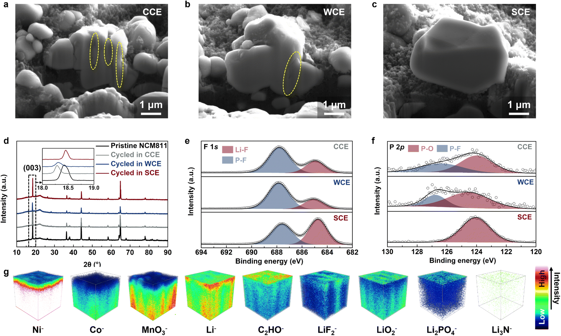 | ||
| Fig. 5 FIB-SEM images of cycled NCM811 cathodes using different electrolytes: (a) CCE, (b) WCE, (c) SCE. (d) XRD patterns of pristine and cycled NCM811 cathodes in the studied electrolytes. The inset shows a locally amplified XRD pattern. (e) The F 1s spectra and (f) P 2p spectra comparison of the cycled NCM811 cathodes in different electrolytes. (g) 3D views of the CEI composition detected by TOF-SIMS depth sputtering on the surface of cycled NCM811 using SCE. | ||
Based on the characterization and testing results, we propose the mechanism by which SCE affects high-voltage LMBs, as illustrated in Fig. 6a. The SCE, characterized by strong Coulomb interactions, forms an anion-dominant solvation structure. This solvation structure not only accelerates the de-solvation process of Li+ but also facilitates the formation of stable interfacial protection layers at both the cathode and anode, promoting fast Li+ transport and inhibiting the decomposition of DME. Consequently, these effects enable stable cycling and fast charge–discharge in high-voltage LMBs. Our designed SCE fundamentally differs from traditional WSE and HCE in its approach to solvation structure regulation. SCE leverages low-dissociation salts to tailor solvation without being confined to a specific solvent or concentration. In contrast, WSE modifies solvation by reducing the solvent's coordinating ability, whereas HCE increases salt concentration to lower the free solvent content, thereby enhancing anion participation in the inner solvation shell. Moreover, WSE and HCE typically employ highly dissociative LiFSI, which often corrodes the current collector.59 In contrast, SCE avoids the use of LiFSI, thereby exhibiting excellent high-voltage stability. To further verify the practicality of SCE, we assembled Li-NCM811 full cells under practical conditions. With a cathode loading of 8.3 mg cm−2 and thin Li foil (50 μm), the Li-NCM811 full cell based on SCE demonstrated stable cycling for over 500 cycles, with a capacity retention of 74.4% (Fig. 6b and S38†). Despite the cathode loading being elevated to 18 mg cm−2 and the electrolyte volume reduced to 25 μL (lean electrolyte), the SCE-based Li-NCM811 full cell exhibits stable cycling behavior under harsh conditions, thereby validating the practical applicability of SCE in LMBs (Fig. S39†). Moreover, when a commercial NCM811 cathode (loading of 18 mg cm−2) was used to assemble an anode-free LMB, the Cu-NCM811 cell using SCE also exhibited stable cycling for over 60 cycles, with a capacity retention of 63.8% and an ACE of 97.5%, further indicating the promising application potential of SCE (Fig. 6c and S40†).60 Importantly, to demonstrate the universality of this strong Coulomb interaction electrolyte design principle, we further reduced the electrolyte concentration to an ultra-low level of 0.1 M, with a composition of 0.05 M LiNO3 + 0.05 M LiPO2F2 in DME/FEC (8:2, v/v), and evaluated its electrochemical performance in high-voltage LMBs. Surprisingly, even at this ultra-low concentration of 0.1 M, the SCE enabled the Li-NCM811 cell to maintain good rate performance at a cutoff voltage of 4.4 V, with a discharge-specific capacity of over 120 mA h g−1 at 5C (Fig. 6d and S41†). Additionally, the Li-NCM811 cell using SCE also exhibited excellent cycling stability, maintaining stable performance for more than 200 cycles under 2C charge–discharge conditions, with a capacity retention of 87.3% (Fig. 6e and S42†). The superior electrochemical performance of ultra-low concentration SCE highlights its significant advantages over previously reported low-concentration electrolytes (Table S1†).
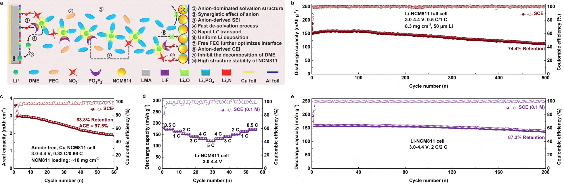 | ||
| Fig. 6 Schematic diagram of the effect mechanism of SCE on high-voltage LMBs. (b) Long-term cycling performance of the Li-NCM811 full cell and (c) Cu-NCM811 anode-free cell using SCE (test conditions are 8.3 mg cm−2, 50 μm Li, 0.5C/1C, and 18 mg cm−2, 0.33C/0.66C, respectively; 3.0–4.4 V, 1C = 180 mA g−1). (d) Rate and (e) long-term cycling performance of the Li-NCM811 cell using SCE with a salt concentration of 0.1 M. (SCE composition is 0.05 M LiNO3 + 0.05 M LiPO2F2 in DME/FEC (8:2, v/v); test conditions are 0.5C, 1C, 2C, 3C, 4C, 5C, and 2C/2C, respectively; 3.0–4.4 V, 1C = 180 mA g−1). | ||
Conclusions
In conclusion, we present a novel strategy for designing high-voltage electrolytes by adjusting the interaction strengths among Li+, anions, and solvent molecules. The strong Coulomb interaction between LiNO3 and LiPO2F2 facilitates the creation of an anion-dominated solvation structure, which enables DME-based electrolytes to maintain excellent high-voltage stability (4.4 V) at an ultra-low concentration of 0.1 M. The unique synergistic effects of LiNO3 and LiPO2F2 result in the formation of an inorganic interface protection layer, consisting of LiF, Li3PO4, and Li3N, on both electrode surfaces. This protective layer is crucial for preserving electrode integrity and suppressing side reactions. Electrochemical performance tests show that Li-NCM811 cells with SCE deliver impressive rate capabilities (20C/120.8 mA h g−1) and long-term cycle stability (5C/1000 cycles). Even under practical conditions, the Li-NCM811 full cell using SCE demonstrates stable cycling for over 500 cycles. This work not only presents a novel approach to high-voltage electrolyte design but also offers a high-performance, low-cost electrolyte for practical LMBs.Data availability
Data are available from the authors on reasonable request.Author contributions
Z. J. and C. L. conceived and designed this work. C. L. and Z. J. carried out the synthesis, electrochemical measurements and computational calculations. Z. J., Y. Z., W. X., J. Z., S. W., M. S. and Y. L. participated in the analysis of the data. All authors discussed and revised the manuscript.Conflicts of interest
There are no conflicts to declare.Acknowledgements
This work was financially supported by the National Natural Science Foundation of China (22308003, 52471027), the Natural Science Foundation of Anhui Province (2308085QB50), the Natural Science Foundation of Anhui Provincial Education Department (2022AH020033 and 2022AH010025), and the Key Scientific Research Project of Colleges and Universities in Henan (5201039140296). The authors also acknowledge the Shiyanjia Lab (https://www.shiyanjia.com) for the XPS and TOF-SIMS measurements.References
- K. Hatzell, W. Chang, W. Bao, M. Cai, T. Glossmann, S. Kalnaus, B. Liaw, Y. S. Meng, R. Mohtadi and Y. Wang, Aligning lithium metal battery research and development across academia and industry, Joule, 2024, 8, 1550–1555 CrossRef CAS.
- A. Yamada, Hidden Negative Issues and Possible Solutions for Advancing the Development of High-Energy-Density in Lithium Batteries: A Review, Adv. Sci., 2024, 11, 2401739 CAS.
- H. Liang, L. Wang, L. Sheng, H. Xu, Y. Song and X. He, Focus on the Electroplating Chemistry of Li Ions in Nonaqueous Liquid Electrolytes: Toward Stable Lithium Metal Batteries, Electrochem. Energy Rev., 2022, 5, 23 CAS.
- L. Dong, S. Zhong, B. Yuan, Y. Ji, J. Liu, Y. Liu, C. Yang, J. Han and W. He, Electrolyte Engineering for High-Voltage Lithium Metal Batteries, Research, 2022, 2022, 9837586 CAS.
- Q. Liu, Y. Liu, Z. Chen, Q. Ma, Y. Hong, J. Wang, Y. Xu, W. Zhao, Z. Hu, X. Hong, J. Wang, X. Fan and H. B. Wu, An Inorganic-Dominate Molecular Diluent Enables Safe Localized High Concentration Electrolyte for High-Voltage Lithium-Metal Batteries, Adv. Funct. Mater., 2023, 33, 2209725 CAS.
- J. Shi, C. Xu, J. Lai, Z. Li, Y. Zhang, Y. Liu, K. Ding, Y. P. Cai, R. Shang and Q. Zheng, An Amphiphilic Molecule-Regulated Core-Shell-Solvation Electrolyte for Li-Metal Batteries at Ultra-Low Temperature, Angew. Chem., Int. Ed., 2023, 62, e202218151 CAS.
- J. Zhang, H. Zhang, R. Li, L. Lv, D. Lu, S. Zhang, X. Xiao, S. Geng, F. Wang, T. Deng, L. Chen and X. Fan, Diluent decomposition-assisted formation of LiF-rich solid–electrolyte interfaces enables high-energy Li-metal batteries, J. Energy Chem., 2023, 78, 71–79 CAS.
- Z. Li, L. Yu, C. X. Bi, X. Y. Li, J. Ma, X. Chen, X. Q. Zhang, A. Chen, H. Chen, Z. Zhang, L. Z. Fan, B. Q. Li, C. Tang and Q. Zhang, A three-way electrolyte with ternary solvents for high-energy-density and long-cycling lithium–sulfur pouch Cells, SusMat, 2024, 4, e191 CAS.
- Y. M. Kim, B. K. Park, S. Kang, S. J. Yang, S. H. Choi, D. J. Yoo and K. J. Kim, Bespoke Dual-Layered Interface Enabled by Cyclic Ether in Localized High-Concentration Electrolytes for Lithium Metal Batteries, Adv. Funct. Mater., 2024, 2408365 CrossRef CAS.
- G. Zhang, J. Li, Q. Wang, H. Wang, J. Wang, K. Yu, J. Chang, C. Wang, X. Hong, Q. Ma and Y. Deng, A Nonffammable Electrolyte for High-Voltage Lithium Metal Batteries, ACS Energy Lett., 2023, 8, 2868–2877 CrossRef CAS.
- J. Qian, W. A. Henderson, W. Xu, P. Bhattacharya, M. Engelhard, O. Borodin and J. G. Zhang, High rate and stable cycling of lithium metal anode, Nat. Commun., 2015, 6, 6362 CrossRef CAS PubMed.
- L. Suo, Y. S. Hu, H. Li, M. Armand and L. Chen, A new class of Solvent-in-Salt electrolyte for high-energy rechargeable metallic lithium batteries, Nat. Commun., 2013, 4, 1481 Search PubMed.
- Y. Yamada, J. Wang, S. Ko, E. Watanabe and A. Yamada, Advances and issues in developing saltconcentrated battery electrolytes, Nat. Energy, 2019, 4, 269–280 CAS.
- X. Ren, L. Zou, X. Cao, M. H. Engelhard, W. Liu, S. D. Burton, H. Lee, C. Niu, B. E. Matthews, Z. Zhu, C. Wang, B. W. Arey, J. Xiao, J. Liu and J. G. Zhang, Enabling High-Voltage Lithium-Metal Batteries under Practical Conditions, Joule, 2019, 3, 1662–1676 CAS.
- X. Ren, P. Gao, L. Zou, S. Jiao, X. Cao, X. Zhang, H. Jia, M. H. Engelhard, B. E. Matthews, H. Wu, H. Lee, C. Liu, C. Wang, B. W. Arey, J. Xiao, J. Liu, J. G. Zhang and W. Xu, Role of inner solvation sheath within salt–solvent complexes in tailoring electrode/electrolyte interphases for lithium metal batteries, Proc. Natl. Acad. Sci. U.S.A., 2020, 117, 28603–28613 CAS.
- S. Zhang, R. Li, T. Deng, Q. Ma, X. Hong, H. Zhang, R. Zhang, S. Ding, Y. Wu, H. Zhu, M. Li, H. Zhang, D. Lu, B. Ma, L. Lv, Y. Li, L. Chen, Y. Shen, R. Guo and X. Fan, Oscillatory solvation chemistry for a 500 Wh kg−1 Li-metal pouch cell, Nat. Energy, 2024, 1–12 Search PubMed.
- M. Kim, J. An, S. J. Shin, I. Hwang, J. Lee, Y. Park, J. Kim, E. Park, J. Kim, G. Park, S. Kim, A. Coskun and J. W. Choi, Anti-corrosive electrolyte design for extending the calendar life of lithium metal batteries, Energy Environ. Sci., 2024, 17, 6079–6090 CAS.
- J. A. Lee, S. Kim, Y. Cho, S. H. Kweon, H. Kang, J. H. Byun, E. Kwon, S. Seo, W. Kim, K. H. Ryu, S. K. Kwak, S. Hong and N. S. Choi, Compositionally Sequenced Interfacial Layers for High-Energy Li-Metal Batteries, Adv. Sci., 2024, 11, 2198–3844 Search PubMed.
- Z. Jiang, Y. Deng, J. Mo, Q. Zhang, Z. Zeng, Y. Li and J. Xie, Switching Reaction Pathway of Medium-Concentration Ether Electrolytes to Achieve 4.5 V Lithium Metal Batteries, Nano Lett., 2023, 23, 8481–8489 CAS.
- Z. Jiang, T. Yang, C. Li, J. Zou, H. Yang, Q. Zhang and Y. Li, Synergistic Additives Enabling Stable Cycling of Ether Electrolyte in 4.4 V Ni-Rich/Li Metal Batteries, Adv. Funct. Mater., 2023, 33, 2306868 CAS.
- T. Yang, L. Li, J. Zou, Y. Yao, Q. Zhang, Z. Jiang and Y. Li, A Safe Ether Electrolyte Enabling High-Rate Lithium Metal Batteries, Adv. Funct. Mater., 2024, 2404945 CAS.
- H. Zheng, H. Xiang, F. Jiang, Y. Liu, Y. Sun, X. Liang, Y. Feng and Y. Yu, Lithium Diffuorophosphate-Based Dual-Salt Low Concentration Electrolytes for Lithium Metal Batteries, Adv. Energy Mater., 2024, 14, 1614–6832 Search PubMed.
- P. Li, H. Zhang, J. Lu and G. Li, Low Concentration Sulfolane-based Electrolyte for High Voltage Lithium Metal Batteries, Angew. Chem., Int. Ed., 2023, 62, e202216312 CAS.
- R. Deng, F. Chu, F. Kwofie, Z. Guan, J. Chen and F. Wu, A Low-Concentration Electrolyte for High-Voltage Lithium-Metal Batteries: Fluorinated Solvation Shell and Low Salt Concentration Effect, Angew. Chem., Int. Ed., 2022, 61, e202215866 CAS.
- Z. Liu, W. Hou, H. Tian, Q. Qiu, I. Ullah, S. Qiu, W. Sun, Q. Yu, J. Yuan, L. Xia and X. Wu, An Ultralow-concentration and Moisture-resistant Electrolyte of Lithium Difluoro(oxalato)borate in Carbonate Solvents for Stable Cycling in Practical Lithium-ion Batteries, Angew. Chem., Int. Ed., 2024, 63, e202400110 CrossRef CAS PubMed.
- J. Mo, Y. Yao, C. Li, H. Yang, H. Li, Q. Zhang, Z. Jiang and Y. Li, A low-concentration all-fluorinated electrolyte for stable lithium metal batteries, Chem. Commun., 2022, 58, 12463–12466 CAS.
- P. Xiao, X. Yun, Y. Chen, X. Guo, P. Gao, G. Zhou and C. Zheng, Insights into the solvation chemistry in liquid electrolytes for lithium-based rechargeable batteries, Chem. Soc. Rev., 2023, 52, 5255–5316 RSC.
- Z. Li, H. Rao, R. Atwi, B. M. Sivakumar, B. Gwalani, S. Gray, K. S. Han, T. A. Everett, T. A. Ajantiwalay, V. Murugesan, N. N. Rajput and V. G. Pol, Non-polar ether-based electrolyte solutions for stable high-voltage non-aqueous lithium metal batteries, Nat. Commun., 2023, 14, 1–13 CAS.
- J. Zhang, Q. Li, Y. Zeng, Z. Tang, D. Sun, D. Huang, Y. Tang and H. Wang, Weakly Solvating Cyclic Ether Electrolyte for High-Voltage Lithium Metal Batteries, ACS Energy Lett., 2023, 8, 1752–1761 CrossRef CAS.
- Y. X. Yao, X. Chen, C. Yan, X. Q. Zhang, W. L. Cai, J. Q. Huang and Q. Zhang, Regulating Interfacial Chemistry in Lithium-Ion Batteries by a Weakly-Solvating Electrolyte, Angew. Chem., 2020, 133, 4136–4143 CrossRef.
- T. Ma, Y. Ni, Q. Wang, W. Zhang, S. Jin, S. Zheng, X. Yang, Y. Hou, Z. Tao and J. Chen, Optimize Lithium Deposition at Low Temperature by Weakly Solvating Power Solvent, Angew. Chem., 2022, 134, e202207927 Search PubMed.
- Z. Jiang, J. Mo, C. Li, H. Li, Q. Zhang, Z. Zeng, J. Xie and Y. Li, Anion-Regulated Weakly Solvating Electrolytes for High-Voltage Lithium Metal Batteries, Energy Environ. Mater., 2022, 6, e12440 CrossRef.
- C. Jin, T. Liu, O. Sheng, M. Li, T. Liu, Y. Yuan, J. Nai, Z. Ju, W. Zhang, Y. Liu, Y. Wang, Z. Lin, J. Lu and X. Tao, Rejuvenating dead lithium supply in lithium metal anodes by iodine redox, Nat. Energy, 2021, 6, 378–387 CrossRef CAS.
- Z. Huang, Z. Xiao, R. Jin, Z. Li, C. Shu, R. Shi, X. Wang, Z. Tang, W. Tang and Y. Wu, A Comprehensive Review on Liquid Electrolyte Design for LowTemperature Lithium/Sodium Metal Batteries, Energy Environ. Sci., 2024, 17, 5365–5386 RSC.
- U. Pal, D. Rakov, B. Lu, B. Sayahpour, F. Chen, B. Roy, D. R. Macfarlane, M. Armand, P. C. Howlett, Y. S. Meng and M. Forsyth, Interphase control for high performance lithium metal batteries using ether aided ionic liquid Electrolyte, Energy Environ. Sci., 2022, 15, 1907–1919 CAS.
- Z. Cui, Z. Jia, D. Ruan, Q. Nian, J. Fan, S. Chen, Z. He, D. Wang, J. Jiang, J. Ma, X. Ou, S. Jiao, Q. Wang and X. Ren, Molecular anchoring of free solvents for high-voltage and high-safety lithium metal Batteries, Nat. Commun., 2024, 15, 2033 CAS.
- Z. Jiang, Z. Zeng, X. Liang, L. Yang, W. Hu, C. Zhang, Z. Han, J. Feng and J. Xie, Fluorobenzene, A Low-Density, Economical, and Bifunctional Hydrocarbon Cosolvent for Practical Lithium Metal Batteries, Adv. Funct. Mater., 2020, 31, 2005991 Search PubMed.
- X. Li, M. Li, Y. Liu, Y. Jie, W. Li, Y. Chen, F. Huang, Y. Zhang, T. M. Sohail, S. Wang, X. Zhu, T. Cheng, M. D. Gu, S. Jiao and R. Cao, Fast Interfacial Deffuorination Kinetics Enables Stable Cycling of Low-Temperature Lithium Metal Batteries, J. Am. Chem. Soc., 2024, 146, 17023–17031 CAS.
- J. Xiao, Q. Li, Y. Bi, M. Cai, B. Dunn, T. Glossmann, J. Liu, T. Osaka, R. Sugiura, B. Wu, J. Yang, J. G. Zhang and M. S. Whittingham, Understanding and applying coulombic efficiency in lithium metal batteries, Nat. Energy, 2020, 5, 561–568 CAS.
- B. D. Adams, J. Zheng, X. Ren, W. Xu and J. G. Zhang, Accurate Determination of Coulombic Efffciency for Lithium Metal Anodes and Lithium Metal Batteries, Adv. Energy Mater., 2017, 8, 1702097 Search PubMed.
- C. Jing, Z. Peng, K. Yan, L. Chen, C. Zhang and W. Wei, Entropy-Driven Hybrid Gel Electrolyte Enables Practical HighVoltage Lithium Metal Batteries, ACS Appl. Mater. Interfaces, 2024, 16, 33647–33656 CAS.
- A. M. Li, O. Borodin, T. P. Pollard, W. Zhang, N. Zhang, S. Tan, F. Chen, C. Jayawardana, B. L. Lucht, E. Hu, X. Q. Yang and C. Wang, Methylation enables the use of fluorine-free ether electrolytes in high-voltage lithium metal batteries, Nat. Chem., 2024, 16, 922–929 CAS.
- G. X. Li, V. Koverga, A. Nguyen, R. Kou, M. Ncube, H. Jiang, K. Wang, M. Liao, H. Guo, J. Chen, N. Dandu, A. T. Ngo and D. Wang, Enhancing lithium-metal battery longevity through minimized coordinating diluent, Nat. Energy, 2024, 9, 817–827 CAS.
- S. Tan, Z. Shadike, J. Li, X. Wang, Y. Yang, R. Lin, A. Cresce, J. Hu, A. Hunt, I. Waluyo, L. Ma, F. Monaco, P. Cloetens, J. Xiao, Y. Liu, X. Q. Yang, K. Xu and E. Hu, Additive engineering for robust interphases to stabilize high-Ni layered structures at ultra-high voltage of 4.8 V, Nat. Energy, 2022, 7, 484–494 CAS.
- X. Zhang, Y. Wang, Z. Ouyang, S. Wang, X. Zhao, Q. Xu, B. Yuan, X. Yue, Z. Liang, S. Geng, S. Tang and H. Sun, Dual-Functional Lithium Nitrate Mediator Eliminating Water Hazard for Practical Lithium Metal Batteries, Adv. Energy Mater., 2023, 14, 2303048 Search PubMed.
- A. Tornheim, M. He, C. C. Su and Z. Zhang, The Role of Additives in Improving Performance in High Voltage Lithium-Ion Batteries with Potentiostatic Holds, J. Electrochem. Soc., 2017, 164, A6366 CAS.
- Z. Jiang, C. Li, T. Yang, Y. Deng, J. Zou, Q. Zhang and Y. Li, Fluorine-Free Lithium Metal Batteries with a Stable LiF-Free Solid Electrolyte Interphase, ACS Energy Lett., 2024, 9, 1389–1396 CAS.
- M. S. Kim, Z. Zhang, J. Wang, S. T. Oyakhire, S. C. Kim, Z. Yu, Y. Chen, D. T. Boyle, Y. Ye, Z. Huang, W. Zhang, R. Xu, P. Sayavong, S. F. Bent, J. Qin, Z. Bao and Y. Cui, Revealing the Multifunctions of Li3N in the Suspension Electrolyte for Lithium Metal Batteries, ACS Nano, 2023, 17, 3168–3180 CAS.
- W. Zhang, et al., Ni-rich LiNi0·8Co0·1Mn0·1O2 coated with Li-ion conductive Li3PO4 as competitive cathodes for high-energy-density lithium ion batteries, Electrochim. Acta, 2020, 340, 135871 CrossRef CAS.
- S.-Y. Liao, S.-F. Cui, Y.-Z. Li, W.-X. Cheng, X.-W. Huang, J. Zhang, T.-T. Cui, X.-G. Shu and Y.-G. Min, Wrinkled and flexible N-doped MXene additive for improving the mechanical and electrochemical properties of the nickel-rich LiNi0.8Co0.1Mn0.1O2 cathode, Electrochim. Acta, 2022, 410, 139989 CrossRef CAS.
- C. B. Jin, N. Yao, Y. Xiao, J. Xie, Z. Li, X. Chen, B. Q. Li, X. Q. Zhang, J. Q. Huang and Q. Zhang, Taming Solvent–Solute Interaction Accelerates Interfacial Kinetics in Low-Temperature Lithium Metal Batteries, Adv. Mater., 2022, 35, 2208340 CrossRef PubMed.
- S. Duan, S. Zhang, Y. Li, R. Guo, L. Lv, R. Li, Z. Wu, M. Li, S. Xiao, L. Chen, Y. Shi, T. Deng and X. Fan, H-Transfer Mediated Self-Enhanced Interphase for High-Voltage Lithium-Ion Batteries, ACS Energy Lett., 2024, 9, 3578–3586 CrossRef CAS.
- X. Wu, Z. Piao, M. Zhang, G. Lu, C. Li, K. Jia, Z. Zhuang, R. Gao and G. Zhou, In Situ Construction of a Multifunctional Interphase Enabling Continuous Capture of Unstable Lattice Oxygen Under Ultrahigh Voltages, J. Am. Chem. Soc., 2024, 146, 14036–14047 CrossRef CAS PubMed.
- Y. Wang, Y. Liu, Y. Tu and Q. Wang, Reductive Decomposition of Solvents and Additives toward Solid-Electrolyte Interphase Formation in Lithium-Ion Battery, J. Phys. Chem. C, 2020, 124, 9099–9108 CAS.
- X. Liu, Y. Li, J. Liu, H. Wang, X. Zhuang and J. Ma, 570 Wh kg−1-Grade Lithium Metal Pouch Cell with 4.9V Highly Li+ Conductive Armor-Like Cathode Electrolyte Interphase via Partially Fluorinated Electrolyte Engineering, Adv. Mater., 2024, 36, 2401505 CAS.
- W. Zhao, G. Zheng, M. Lin, W. Zhao, D. Li, X. Guan, Y. Ji, G. F. Ortiz and Y. Yang, Toward a stable solid-electrolyte-interfaces on nickel-rich cathodes: LiPO2F2 salt-type additive and its working mechanism for LiNi0.5Mn0.25Co0.25O2 cathodes, J. Power Sources, 2018, 380, 149–157 CAS.
- J. Kim, T. Yoon and O. B. Chae, Behavior of NO3−-Based Electrolyte Additive in Lithium Metal Batteries, Batteries, 2024, 10, 135 CrossRef CAS.
- Y. Jie, S. Wang, S. Weng, Y. Liu, M. Yang, C. Tang, X. Li, Z. Zhang, Y. Zhang, Y. Chen, F. Huang, Y. Xu, W. Li, Y. Guo, Z. He, X. Ren, Y. Lu, K. Yang, S. Cao, H. Lin, R. Cao, P. Yan, T. Cheng, X. Wang, S. Jiao and D. Xu, Towards long-life 500 Wh kg−1 lithium metal pouch cells via compact ion-pair aggregate Electrolytes, Nat. Energy, 2024, 9, 987–998 CAS.
- J. Zou, H. Yang, S. Wu, Z. Xiao, Z. Jiang, W. Shen and Y. Li, Tuning steric hindrance of cyclic ether electrolytes enables high-voltage lithium metal batteries, J. Colloid Interface Sci., 2025, 683, 281–290 CrossRef CAS PubMed.
- P. Xu, F. Huang, Y. Sun, Y. Lei, X. Cao, S. Liang and G. Fang, Anode-Free Alkali Metal Batteries: From Laboratory to Practicability, Adv. Funct. Mater., 2024, 2406080 CAS.
Footnote |
| † Electronic supplementary information (ESI) available. See DOI: https://doi.org/10.1039/d4sc07393b |
| This journal is © The Royal Society of Chemistry 2025 |