
 Open Access Article
 This Open Access Article is licensed under a Creative Commons Attribution-Non Commercial 3.0 Unported Licence
Investigation of luminescence properties and ratiometric thermometry through yellow-to-blue Dy3+ emission in Ca3La7(SiO4)5(PO4)O2 apatite
Abir Douziab,
Sami Slimi ac,
Eduard Madirovd,
Josep Maria Serresac,
Rosa Maria Soléa,
Ezzedine Ben Salemb,
Andrey Turshatovd,
Bryce S. Richardsd and
Xavier Mateos*ae
ac,
Eduard Madirovd,
Josep Maria Serresac,
Rosa Maria Soléa,
Ezzedine Ben Salemb,
Andrey Turshatovd,
Bryce S. Richardsd and
Xavier Mateos*ae
aUniversitat Rovira i Virgili (URV), Física i Cristal·lografia de Materials (FiCMA), Marcel·li Domingo 1, Tarragona, 43007, Spain. E-mail: xavier.mateos@urv.cat
bI.P.E.I. of Monastir, Research Laboratory: Physico-chemistry of Innovative Materials LR24ES16, University of Monastir, 5019, Tunisia
cEurecat, Centre Tecnològic de Catalunya, C. Marcel·lí Domingo 2, 43007 Tarragona, Spain
dInstitute of Microstructure Technology, Karlsruhe Institute of Technology, Hermann-von-Helmholtz-Platz 1, 76344 Eggenstein-Leopoldshafen, Germany
eSerra Húnter Fellow, University Rovira i Virgili, Spain
First published on 10th June 2025
Abstract
Dy3+-doped Ca3La7(SiO4)5(PO4)O2 (CLSPO) phosphors were synthesized via a solid-state reaction method and characterized for their structural, optical, and thermometric properties. X-ray diffraction (XRD) and Rietveld refinement confirmed a hexagonal apatite-type structure (P63/m) with refined lattice parameters of a = b = 9.604(3) Å, c = 7.103(1) Å. First-principles calculations for the undoped crystal revealed a direct bandgap of 4.08 eV, confirming CLSPO as a suitable host material for luminescent applications. Photoluminescence spectra exhibited characteristic Dy3+ emissions, with two blue bands (B1: 468 nm, B2: 479 nm) and two yellow bands (Y1: 543 nm, Y2: 575 nm). The yellow-to-blue (Y/B) intensity ratio displayed a strong temperature dependence, establishing CLSPO:Dy3+ as a promising candidate for luminescence-based thermometry. The optimal Dy3+ doping concentration was determined to be 3 at%, beyond which concentration quenching effects were observed. Photoluminescence studies further demonstrated that electric dipole–dipole interactions govern the dominant energy transfer mechanism, as evidenced by concentration-dependent quenching behavior. The absolute photoluminescence quantum yield (PLQY) was 5.7%, and Arrhenius analysis determined an activation energy of 0.11 eV. The decay time decreases with increasing Dy3+ concentration (from 658 μs at 0.5 at% Dy3+ to 252 μs at 10 at%). The fluorescence intensity ratio (FIR) method for optical thermometry revealed an absolute sensitivity (Sa) of 3.27 10−4 K−1 at 298 K, while the repeatability (R) of the Y/B ratio exhibited a reproducibility of 95.88% at 298 K, ensuring consistent and reliable temperature sensing performance. Furthermore, the luminescence remained stable over three hours of multiple heating–cooling cycles (298–523 K), confirming excellent photostability and reversibility. These results establish CLSPO:Dy3+ phosphors as highly efficient, thermally stable, and optically robust materials for next-generation temperature sensors, solid-state lighting, and advanced photonic applications.
1. Introduction
Over the past few decades, trivalent lanthanide ions (Ln3+) doped into phosphors have attracted considerable attention due to their extraordinary photoluminescence properties. These ions exhibit unique phenomena such as upconversion luminescence and large Stokes-shifted emissions, which are highly beneficial for a wide range of optoelectronic applications, including lasers, light-emitting diodes (LEDs), fiber-optic amplifiers, color displays, and various types of sensors. The versatility and efficiency of Ln3+-doped phosphors have firmly established them as foundational components in the advancement of modern photonic technologies.1–4 Among the various trivalent lanthanide ions (Ln3+), dysprosium (Dy3+) stands out as an exceptional activator due to its ability to emit light across a broad spectrum, ranging from visible to near-infrared wavelengths. This emission results from electronic transitions between the excited energy level 4F9/2 and a series of intermediate states within the manifold 6Hn (where n = 15/2, 13/2, 11/2, 9/2, and 7/2). These transitions occur at distinct wavelengths, making Dy3+ particularly valuable for applications that require diverse emission profiles, such as advanced optical devices and luminescent materials.5,6The visible emission of the Dy3+ ion is primarily defined by two distinct emission bands in the blue and yellow regions of the spectrum. The blue emission, which corresponds to the transition from the 4F9/2 energy level to 6H15/2, is a magnetic dipole transition. This type of transition is largely insensitive to the local crystal field, meaning that it remains relatively insensitive to changes in the surrounding medium. In contrast, the yellow emission, which occurs during the transition from 4F9/2 to 6H13/2, is an electric dipole transition. This transition is highly sensitive to the local crystal field, meaning that even subtle changes in the field environment around Dy3+ ions can significantly influence the intensity and characteristics of the yellow emission. This sensitivity makes yellow emission particularly useful for studying the local environment in various luminescent materials and applications.7–10
By combining the blue and yellow emissions of Dy3+, white light emission can be achieved in singly Dy3+-doped phosphors.11–16 Moreover, the relative intensities of these two emissions provide valuable insights into key aspects of the material, including energy transfer processes, local symmetry, and the coordination environment of Dy3+ ions. However, singly Dy3+-doped phosphors often exhibit relatively low photoluminescence quantum yield (PLQY) due to the absence of efficient sensitization pathways. For instance, Dy3+-doped nano-glass-ceramics have been reported to exhibit a PLQY of approximately 15.2%,17 while Dy2O3-doped alkaline-earth borate glasses have demonstrated a PLQY of 23.74% under 453 nm laser excitation.18 Understanding these factors is essential for optimizing the phosphor's efficiency and expanding its applicability in optical devices.9,11,15,19
In addition to factors such as host material, pump wavelengths and Dy3+ ion concentration, temperature plays a key role in tuning the blue-to-yellow intensity ratio of Dy3+-activated luminescent materials. Temperature changes can influence emission properties, enabling fine-tuning of the output color, which is essential for optimizing the performance of these materials in various applications.9,20–22 Dy3+-doped phosphors are well established in the field of thermometry, especially through the use of the luminescence intensity ratio method. This technique typically relies on the variation between two blue emission lines, which arise from transitions involving the thermally coupled energy levels 4I15/2 and 4F9/2 in the ground state 6H15/2.4,9,20,22–24
Due to the presence of numerous intermediate energy levels within the Dy3+ ion, the thermally coupled energy states 4I15/2 and 4F9/2 govern several temperature-dependent emission processes. The Boltzmann distribution can be applied to describe the population dynamics between these two levels, which influences the intensity ratio of the two blue emission lines, corresponding to the 4I15/2 → 6H15/2 and 4F9/2 → 6H15/2 transitions. This population distribution also affects the two yellow emission lines, corresponding to the 4I15/2 → 6H13/2 and 4F9/2 → 6H13/2 transitions. By considering both blue and yellow emissions, the Boltzmann distribution provides a more complete description of the temperature dependence of the emission intensity ratios. Therefore, in contrast to room temperature, the yellow-to-blue intensity ratio of Dy3+-doped phosphors is expected to show significant variations at elevated temperatures. These variations may lead to observable color changes in the phosphors. In addition, the relationship between the yellow-blue intensity ratio and temperature can be defined quantitatively, enabling this relationship to be used for accurate temperature measurements in thermometry applications.
The optical properties of phosphors doped with Ln3+ ions are influenced both by the specific type of Ln3+ ions used and by the choice of host material. Once Dy3+ ions are incorporated into various inorganic crystalline materials such as apatite-type materials, they can generate a wide range of attractive luminescence properties. As an apatite compound, Ca8La2(PO4)6O2 (CLPO) has been used as a phosphorescent host in various studies.25–27 Zhu et al. synthesized and studied a series of Ce3+-doped CLPO phosphors, whose emission can be modulated to produce different colors.27 Shang et al. produced Ce3+ and Eu2+-activated CLPO phosphors, emitting in the blue region of the spectrum, and explored the mechanisms of luminescence as well as the associated energy transfer processes.26 Fang et al. conducted a systematic study of the photoluminescence properties of Eu3+ doped CLPO-based phosphors.25 In an effort to identify and develop more efficient luminescent materials, and with the aim of optimizing their photoluminescent properties and discovering materials with superior performance, the researchers carried out an in-depth exploration of cation and anion substitutions within the apatite compound. They synthesized and analyzed a series of modified compounds, including Ca2+xLa8−x(SiO4)6−x(PO4)xO2 (CLSPO) doped with Eu2+ ions (where x = 0, 2, 4, 6)28 and Eu3+ ions (where x = 0, 3, 6).29 Additionally, a related study investigated apatites doped with 2% Eu and a wider range of x values (x = 0, 1, 2, 3, 4, 5, 6), focusing on the emission properties of both Eu2+ and Eu3+ ions.30 These studies collectively demonstrate the versatility of apatite-based phosphors in hosting lanthanide ions at various doping levels and oxidation states, providing a foundation for exploring the photoluminescence behavior of new dopant systems such as Dy3+. In this context, Cheng et al. synthesized a series of Eu3+-doped CLSPO phosphors and investigated in detail their photoluminescence properties, Judd–Ofelt analysis, and temperature sensing characteristics via absolute emission intensity.31
In this study, we successfully synthesized CLSPO:Dy3+ phosphors and evaluated their structural, optical, and thermometric properties. The study focuses on the (Y/B) emission ratio, leveraging its sensitivity to both doping concentration and temperature for optical sensing applications.
2. Experimental
2.1. Synthesis
CLSPO:xDy3+ phosphors, with x = 0.5, 1, 2, 3, 4, 5, 7, and 10 at% in the raw materials mixture, were synthesized using the solid-state method in an open atmosphere. High-purity raw materials were utilized: CaCO3 (99.99%, chemPUR), La2O3 (99.99%, Sigma-Aldrich), SiO2 (∼99%, Sigma-Aldrich), (NH4)2HPO4 (≥99.0%, Alfa Aesar), and Dy2O3 (99.9%, chemPUR). The materials were first weighed in stoichiometric proportions, then transferred to an agate mortar in ethanolic medium. They were then carefully ground to obtain a dry, homogeneous mixture. In the next step, the prepared mixture was calcined in a covered alumina crucible at 900 °C for 6 hours. The calcined powder was then reground and compressed into pellets under pressure. These pellets were sintered at 1350 °C for 10 hours in air and finally cooled to room temperature.The chemical reaction to prepare Ca3La7−xDyx(SiO4)5(PO4)O2 phosphors is as follows:

2.2. Characterization methods
The X-ray powder diffraction (XRD) patterns of the CLSPO:xDy3+ series (x = 0–10 at%) were acquired at room temperature using a Shimadzu XRD-6000 diffractometer configured in Bragg–Brentano geometry. The system utilized a Cu X-ray source, a scintillation counter as the detector, and a Ni filter to suppress Kβ radiation. The instrument operated at a tube voltage of 40 kV and a current of 40 mA. Diffraction patterns were recorded over the 2θ range of 5° to 80°, with a scan speed of 2° min−1 and a step size of 0.02°, ensuring high-resolution data suitable for detailed analysis across all samples in the series. For Rietveld refinement, data collection was performed under the same conditions, with a step size of 0.02° and a step time of 2 seconds. The samples were mounted on a Si(510) substrate, chosen for its low background contribution, to enhance signal clarity. The structural refinement was conducted using Match! 3 (Crystal Impact, demo version), enabling accurate determination of the lattice parameters and other structural details. The particle morphology and size were analyzed using transmission electron microscopy (TEM) with a JEOL 1011 microscope, providing detailed insights into the structural features at the nanoscale. The elemental composition of the samples was examined through energy-dispersive X-ray spectroscopy (EDX), conducted on a Thermo Scientific Scios2 field emission scanning electron microscope (FE-SEM). The EDX analysis was facilitated by a Thermo Scientific microanalyzer integrated with Pathfinder software, ensuring precise and comprehensive compositional characterization.The Raman spectra were recorded using a Renishaw InVia confocal Raman microscope, equipped with an edge filter and a 50× Leica objective, employing an Ar+ ion laser as the excitation source (λexc = 514 nm). A Varian Cary 5000 UV-visible-NIR spectrophotometer, equipped with an integrating sphere, was used to measure the diffuse reflectance spectra of the samples at room temperature (RT, 20 °C). The measurements were conducted over the spectral range of 200–700 nm, with a data acquisition interval of 0.5 nm and an integration time of 1 second per data point. The reflectance spectra were obtained from pellet samples with a diameter of 12 mm for photoluminescence spectroscopy under 445 nm excitation, a custom-built optical setup was employed. The setup featured a 445 nm diode laser (FC-445-2W), which was coupled to an optical fiber and a collimating lens to accurately focus the excitation beam onto the sample, delivering an estimated power density of approximately 73.33 W cm−2 at the sample surface. The resulting PL emission was captured using an optical spectral analyzer (OSA, AQ6373E, Yokogawa Electric Corporation), with spectral resolution of 1 nm. To evaluate the temperature-dependent luminescent properties, the samples were mounted on a Linkam THMS600 heating stage. The temperature was varied from 298 K to 523 K, with a step size of 25 K. This setup allowed precise control of the sample temperature during the measurements. The luminescence emission was collected using a 90° geometry, which was chosen specifically to reduce interference from the pump radiation in the recorded spectra. The photoluminescence quantum yield (PLQY) was determined using an optical system based on an integrated sphere (Labsphere, 6′′ diameter, model 3 P-LPM-060-SL). The sample is positioned centrally within the sphere and illuminated by a continuous-wave LED emitting at 365 nm (Thorlabs, M365L3), powered by a laser diode controller (Thorlabs, ITC4001). The excitation spectra, the emission under 350 nm excitation and the luminescence lifetime were recorded using a spectrofluorometer (FS5, Edinburgh Instruments), equipped with a xenon lamp as the excitation source.
3. Results and discussion
3.1. Phase analysis, structural refinement, and morphology study
Fig. 1(a) shows XRD analysis of the crystal structures of CLSPO:xDy3+ phosphors, with x ranging from 0 to 10 at%. The diffraction peaks obtained from the XRD patterns exhibit a strong correlation with the ICSD database entry 140674, which corresponds to the apatite compound Ca2La8(SiO4)6O2 (see Fig. 1(b)). The observed peaks align distinctly with the reference structure, demonstrating excellent consistency with the crystallographic data. Moreover, the absence of additional peaks in the XRD analysis unequivocally confirms the phase purity of the sample, affirming its structural fidelity to the specified database entry. Detailed examination of the CLSPO:x at% Dy3+ samples (x = 0, 0.5, 1, 2, 3, 4, 5, 7 and 10 at%) reveals a hexagonal structure with a P63/m space group. The introduction of Dy3+ ions did not induce secondary crystalline phases. | ||
| Fig. 1 (a) XRD patterns for the CLSPO doped with different concentrations of Dy3+ ions; (b) reference plot downloaded from ICSD database, file number 140674, for the apatite compound Ca2L8(SiO4)6O2; (c) variation of the position of the diffraction peak of the (002) plan as function of Dy3+ ions concentration. | ||
The Dy3+ ions in CLSPO are expected to substitute for trivalent host cations, primarily La3+, which occupies the 4f-type sites in the apatite structure. This preferential substitution arises from the close ionic size match between Dy3+ and La3+ in comparable coordination environments. Based on Shannon's reference, the ionic radius for Dy3+ and La3+ are as follows: Dy3+ has a radius of 0.97 Å at CN = VII and 1.08 Å at CN = IX, while La3+ has a radius of 1.11 Å at CN = VII and 1.22 Å at CN = IX, where CN indicates coordination number32 stability. Since the 4f-site in CLSPO exhibits nine-coordination (CN = IX), Dy3+ preferentially replaces La3+ at this position, as the relatively small size difference helps minimize significant lattice distortion. Additionally, the 4f-site provides a symmetric and spacious environment, further facilitating Dy3+ incorporation while maintaining structural integrity.
In the case of substituting La3+ ions with Dy3+ ions in CLSPO, a reduction in the unit cell volume is evident. This is demonstrated by the shift of the diffraction peak corresponding to (hkl) = (002) in the XRD patterns of the CLSPO phosphors (Fig. 1(c)). This peak progressively shifts toward larger diffraction angles (2θ) with increasing Dy3+ concentration, indicating a decrease in lattice constants and a contraction of the unit cell volume, consistent with Bragg's law. The lattice parameters a, c, and the unit cell volume Vcalc decrease systematically with higher Dy3+ doping levels, as shown in Table 3.
The replacement of La3+ ions in the lattice by Dy3+ is confirmed by the percentage difference in ionic radii (Δr) between activator ions (Dy3+) and host ions (La3+), determined using eqn (1) (ref. 33):
 | (1) |
To gain deeper insights into the structure of CLSPO:Dy3+ and the incorporation behavior of Dy3+ ions within the CLSPO host matrix, Rietveld refinement was performed on a CLSPO:3 at% Dy3+ sample. Fig. 2(a) shows the fitting results, while Table 1 summarizes the refinement parameters. The crystal structure of Ca3La7(SiO4)5(PO4)O2:Eu3+ (ref. 31) served as the initial model for refinement. The calculated profiles match the experimental data perfectly. For CLSPO:3 at% Dy3+, the refined lattice parameters are a = b = 9.604(3) Å, c = 7.103(1) Å, with unit cell volume Vcalc = 567.38 Å3 and theoretical crystal density ρcalc = 4.91 g cm−3 (with formula unit number Z = 1). The refinement reliability factors are Rwp = 12.82%, Rp = 7.72%, and the chi-square (χ2) is 4.75, suggesting a reasonably good fit and satisfactory convergence of the refinement process. Table 2 lists the atomic coordinates, sites, isotropic displacement parameters (Biso), and occupancy factors (O.F.) obtained for sample CLSPO:3 at% Dy3+. This data has enabled us to depict a fragment of the CLSPO:Dy3+ structure projected along a–b crystallographic plan, as presented in Fig. 2(b). Two distinct cationic sites were identified in the structure. The first, referred to as the Ca1|La1|Dy1 site, is located at the 4f crystallographic position. It exhibits nine-fold coordination (see Fig. 2(c)) and possesses C3 symmetry, with Ca1|La1|Dy1–O bond distances ranging from 2.4652(9) to 2.8768(5) Å. The second site, Ca2|La2|Dy2, occupies the 6h position and is seven-coordinated with Cs symmetry,34,35 exhibiting Ca2|La2|Dy2–O distances between 2.3103(2) and 2.7525(7) Å. The cations were connected through isolated PO4/SiO4 tetrahedra. Notably, the oxide ion O4, termed “free oxygen”,36 was excluded from these tetrahedra and could form a short, highly covalent bond with the cation at the 6h site.37 [Ca2|La2|Dy2O7] polyhedra are situated within structural channels formed by six interconnected [Ca1|La1|Dy1O9] polyhedra. These nine-coordinated polyhedra are arranged in metaprism-like columns (see Fig. 2(c)), contributing to the overall framework stability and connectivity. The twist angle (φ) between adjacent triangular faces of the [Ca1|La1|Dy1O9] polyhedron along the crystallographic [001] direction is a key structural parameter used to assess variations in channel volume within the crystal framework. This angle, defined as the [001]-projected angle between the O1–Ca1|La1|Dy1–O2 atoms, is highly sensitive to the local chemical environment and therefore serves as an effective indicator of structural distortion caused by cation substitution. The φ value can be precisely determined using the atomic coordinates of the Ca1|La1|Dy1 cation and its coordinating oxygen atoms O1 and O2. Based on the method proposed by White and Dong,38 the calculated twist angle for the Dy3+-doped sample (CLSPO: 3 at% Dy3+) is 26.81°, which is slightly larger than that of the undoped host material (26.78°), indicating a subtle increase in channel distortion upon Dy3+ incorporation.
 | ||
| Fig. 2 (a) Refinement plots of CLSPO:3 at% Dy3+ sample; (b) view of the crystal structure of CLSPO:Dy3+ phosphor along a–b crystallographic plan; (c) oxygen atoms environment around the two cationic sites 4f and 6h. | ||
| Parameters | Value |
|---|---|
| Sample | CLSPO:3 at% Dy3+ |
| Crystallographic class | Hexagonal |
| Space group | P63/m |
| Laue group | 6/m |
| Cell formula units (Z) | 1 |
| Space group number (setting number) | 176 (1) |
| Lattice parameters | a = b = 9.604 (3) Å, c = 7.103 (1) Å |
| Lattice volume | 567.38 Å3 |
| Diffraction radiation type (wavelength) | Cu-Kα1 (1.54188 Å) |
| Measurement temperature | 295 K |
| Software | Match 3 (crystal impact-demo version) |
| Reliability factors | χ2 = 4.75, Rwp = 12.82, Rp = 7.72, Rexp = 5.88 |
| Atoms | Wyck | x | y | z | O.F. | Biso |
|---|---|---|---|---|---|---|
| Ca1|La1|Dy1 | 4f | 1/3 | 2/3 | −0.0032(1) | 0.5164|0.4674|0.0162 | 1.969(3) |
| Ca2|La2|Dy2 | 6h | 0.2324(5) | −0.0136(7) | 1/4 | 0.1557|0.8200|0.0242 | 1.936(1) |
| Si|P | 6h | 0.4065(2) | 0.3771(4) | 1/4 | 0.8333|0.1666 | 1.337(7) |
| O1 | 6h | 0.3225(1) | 0.4925(1) | 1/4 | 1 | 2.071(5) |
| O2 | 6h | 0.5991(5) | 0.4706(1) | 1/4 | 1 | 2.730(4) |
| O3 | 2a | 0 | 0 | 1/4 | 1 | 1.336(2) |
| O4 | 12i | 0.3461(1) | 0.2625(1) | 0.0727(1) | 1 | 1.179(1) |
| Dy3+ concentration (at%) | a, b (Å) | c (Å) | Vcalc (Å3) |
|---|---|---|---|
| 0 | 9.617(1) | 7.106(1) | 569.16 |
| 3 | 9.604(1) | 7.103(1) | 567.38 |
| 5 | 9.594(3) | 7.101(1) | 566.04 |
| 10 | 9.585(2) | 7.097(1) | 564.66 |
Fig. 3 shows the morphology of the CLSPO:Dy3+ powders synthesized in this study. Fig. 3(a)–(c) show SEM, EDX images and the elemental mapping of the CLSPO:3 at% Dy3+ sample, respectively. The SEM images show that these particles exhibit a relatively high degree of agglomeration and irregularity. This morphology is attributed to the solid-state reaction method used in their preparation, which tends to cause agglomeration and particle heterogeneity. The agglomerates consist of groups of micrometer-sized particles, tightly bound to each other, while the individual particles also appear as entities with specific shapes and sizes.
 | ||
| Fig. 3 (a) SEM image (b) EDX spectra and (c) elemental mapping for the CLSPO:3 at% Dy3+ phosphors. | ||
The EDX analysis, shown in Fig. 3(b), confirms the presence of calcium (Ca), lanthanum (La), silicon (Si), phosphorus (P), oxygen (O), and dysprosium (Dy) in the sample, indicating that all the expected elements are present in the material. In addition, the elemental color mappings, shown in Fig. 3(c), suggest a uniform distribution of these elements throughout the sample at the microscale. Due to the similar X-ray emission energies of La and Dy, a certain degree of overlap is possible in the EDX analysis; however, the observed uniform distribution is consistent with the expected homogeneous incorporation of Dy into the CLSPO matrix. This uniform distribution of elements is particularly beneficial for lighting and display applications, as it promotes coherent and homogeneous luminescence of the CLSPO:Dy3+ phosphorescent material.
It should be noted that the SEM and EDX analyses were performed only for the CLSPO:3 at% Dy3+ composition, selected as representative sample within the studied doping range. While this analysis provides valuable insight into microstructure and elemental dispersion, further investigation across the full Dy3+ concentration range would be needed to assess the influence of doping level on morphology and its correlation with optical properties.
Fig. 4 shows the Raman spectra of the synthesized CLSPO:xDy3+ phosphors (x = 1, 2, 3, 5, 7 and 10 at%), measured at room temperature in the range from 100 to 1200 cm−1. The bands corresponding to PO43− and SiO44− ions have been identified by comparing them with the spectra of pure apatites available in the literature.39,40 The bands at 160, 208 and 290 cm−1 correspond to the external modes associated with the free movements of the PO43− and SiO44− groups, as well as the translational modes of the PO43−, SiO44−, Ca2+ and La3+ ions. The spectra show the bands associated with the vibrational modes of these two tetrahedral groups. The PO43− group was revealed by the significant intensity band around 959 cm−1 associated with symmetrical stretching modes (ν1) and the weaker band observed at a frequency below 525 cm−1 attributed to asymmetrical bending modes (ν4). In addition to the bands of the PO43− group, the spectra of the substituted samples also displayed bands corresponding to the SiO44− groups. The bands around 857 cm−1 were attributed to symmetrical stretching modes (ν1), while those associated with symmetrical bending modes (ν2) were detected around 400 cm−1.
 | ||
| Fig. 4 Raman spectra for CLPSO: x at% Dy3+ with x = 1, 2, 3, 5, 7 and 10. | ||
The study of the electronic structure of the CLSPO host was carried out using first-principles calculations in the CASTEP code, employing the generalized gradient approximation (GGA) with the Perdew–Burke–Ernzerhof (PBE) functional formalism. The electronic bandgap structure, along with the total density of states (TDOS) of the CLSPO crystal, is depicted in Fig. 5(a) and (b). The results indicate that the energy gap between the valence band and conduction band is 4.08 eV, which is slightly lower than the experimentally reported value of 4.4 eV in ref. 31. This underestimation is a well-known limitation of the GGA-PBE functional, which does not fully account for the discontinuity in the exchange–correlation potential when an electron is added to or removed from a system. This limitation, combined with the incomplete treatment of electron–electron interactions, leads to a self-interaction error and a systematic underestimation of the energy difference between the valence band maximum (VBM) and the conduction band minimum (CBM). While more advanced methods such as hybrid functionals (HSE06) or GW corrections could improve the accuracy of the calculated bandgap, the GGA-PBE approach was chosen due to its well-documented balance between computational cost and predictive power, particularly for complex oxide materials. Importantly, the primary goal of this calculation is to gain qualitative insight into the electronic structure, including the relative positions of the valence and conduction bands, rather than to obtain an exact bandgap value.
 | ||
| Fig. 5 (a) Bandgap structure of CLSPO host via density functional theory (DFT) calculation and (b) the corresponding calculated TDOS; bandgap values obtained via the K–M function for: (c) CLSPO:1 at% Dy3+; (d) CLSPO:3 at% Dy3+; and (e) CLSPO:10 at% Dy3+. | ||
To experimentally determine the optical bandgap of the synthesized compounds CLSPO:Dy3+, the absorption spectra for CLSPO:1 at% Dy3+, CLSPO:3 at% Dy3+, and CLSPO:10 at% Dy3+ (see Fig. 5(c)–(e), respectively) were derived from their reflection spectra using the Kubelka–Munk (K–M) function:5
 | (2) |
| αℏν ∝ (ℏν − Eg)n/2. | (3) |
| [F(R)ℏν]2 ∝ (ℏν − Eg)n. | (4) |
Fig. 5(c)–(e) presents the plot of [F(R)ℏν] versus ℏν. By extending the linear portion to the point where [F(R)ℏν] = 0, the optical band gap values for CLSPO doped with 1, 3, and 10 at% Dy3+ are found to be 4.15 eV, 4.10 eV, and 3.97 eV, respectively. As the Dy3+ doping concentration increases, the absorption edge shifts to longer wavelengths, and the Eg value decreases accordingly.
3.2. Photoluminescence excitation and emission properties of CLSPO:Dy3+ phosphors
Fig. 6(a) presents the photoluminescence excitation spectra of CLSPO phosphors doped with 3% Dy3+, with controlled emission wavelengths of 575 nm and 477 nm. Notably, the excitation bands are identical for both wavelengths, with the only variation being in the excitation intensity. The spectrum reveals nine main excitation bands that correspond to spectral transitions from the ground state energy level 6H15/2 to various excited energy levels at specific wavelengths. These transitions occur at 292 nm for 4K13/2/4L13/2, 320 nm for 4K15/2, 334 nm for 4I9/2, 345 nm for 6P7/2, 360 nm for 4I11/2, 386 nm for 6P3/2/6P5/2/4F7/2, 425 nm for 4G11/2, 452 nm for 4I15/2, and 468 nm for 4F9/2. Each band represents the absorption of photons by Dy3+ ions, leading to the excitation of electrons from the ground state 6H15/2 to these specific higher-energy states. These f–f transitions are characteristic of dysprosium ions and are typically observed in photoluminescence or absorption spectra, providing detailed information about the optical properties and electronic structure of materials doped with Dy3+. Among all the excitation wavelengths observed, the 345 nm wavelength, corresponding to the 6H15/2 → 6P7/2 transition in Dy3+ ions, was the most prominent. This strong excitation band was specifically utilized to investigate the photoluminescence behaviors of CLSPO:Dy phosphors. The pronounced intensity of this transition makes it particularly effective for exploring the luminescent properties and potential applications of these phosphors in various optoelectronic devices. | ||
| Fig. 6 (a) Excitation spectra of CLSPO:3 at% Dy3+ phosphor with emission wavelength λem monitored at 575 and 477 nm; (b) emission spectra under the pumping λexc of 345 nm and 445 nm. | ||
Fig. 6(b) shows the emission spectrum of synthesized CLSPO phosphors doped with 3 at% Dy3+ under excitation at 345 nm and 445 nm. The observed emission can be attributed to electronic transitions from higher to lower energy states. The spectrum reveals several sharp peaks at different wavelengths, clearly indicating the distinct electronic transitions characteristic of Dy3+ ions in the material. Photoluminescence spectra reveal four similar emission bands, with a pronounced variation in emission intensity between the two spectra. These bands are centered at 478 nm, 575 nm, 663 nm and 754 nm, corresponding to specific Dy3+ transitions: 4F9/2 → 6H15/2, 4F9/2 → 6H13/2, 4F9/2 → 6H11/2, and 4F9/2 → 6H9/2 + 6F11/2, respectively.5,43 Additionally, the transitions 4I15/2 → 6H15/2 (at 468 nm) and 4I15/2 → 6H13/2 (at 543 nm) are only visible in the emission spectra under 445 nm excitation. This is because the 445 nm wavelength excites Dy3+ ions into lower-energy states, specifically the 4I15/2 level. In contrast, the 345 nm wavelength excites higher-energy states, while the 445 nm excitation matches the energy gap required for the 4I15/2 → 6H15/2 and 4I15/2 → 6H13/2 transitions, making them observable in the 445 nm spectra. This demonstrates how different excitation wavelengths influence the transitions that appear in the emission spectra.
3.3. Excitation and photoluminescence properties of CLSPO:Dy3+ phosphors as a function of concentration
Fig. 7(a) and (b) illustrate the influence of Dy3+ ion concentration on the photoluminescence excitation and emission intensities of CLSPO:x at% Dy3+ phosphors (with x = 0.5, 1, 2, 3, 4, 5, 7, and 10) at room temperature. The photoluminescence excitation spectra were recorded by monitoring emission at 575 nm, while the emission spectra were obtained under 445 nm excitation. Multiple excitation and photoluminescence peaks were observed and are well defined. The positions of these excitation peaks remained unchanged as a function of Dy3+ concentrations, but their intensities differed. The highest excitation intensity was obtained with CLSPO:3 at% Dy3+ phosphors. Similarly, varying Dy3+ concentration did not alter emission band profiles, but it did influence emission intensities. Once again, CLSPO:3 at% Dy3+ phosphors showed the most intense emission. It can therefore be concluded that the optimum concentration of Dy3+ is 3 at%, which is why CLSPO:3 at% Dy3+ phosphors have been selected for the following study. | ||
| Fig. 7 (a) Photoluminescence excitation spectra (λem = 575 nm); (b) photoluminescence emission spectra (λexc = 445 nm) of CLSPO phosphors with varying concentrations of Dy3+; (c) photoluminescence intensity of Y2 and B2 and intensity ratio of Y2/B2 as a function of the concentration of Dy3+ in CLSPO:Dy3+ phosphors; (d) PLQY in the 450–900 nm range under 365 nm excitation vs. the Dy3+ doping concentration. | ||
The 4f9 electronic configuration of Dy3+ ions allows multiple 4f–4f transitions. At room temperature, the blue emission (B2) from the 4F9/2 → 6H15/2 transition and the yellow emission (Y2) from the 4F9/2 → 6H13/2 transition are the most prominent, as shown in Fig. 7(b). The yellow-to-blue (Y/B) emission ratio is particularly sensitive to the local symmetry around Dy3+ ions, since the yellow emission is hypersensitive to crystal field effects, while the blue emission is largely insensitive. Therefore, the Y/B ratio serves as a useful probe of the Dy3+ local environment.
Fig. 7(c) illustrates the photoluminescence intensities of Y2 and B2 as a function of Dy3+ concentration in CLSPO phosphors at room temperature. It is clear that as the concentration of Dy3+ increases, the photoluminescence intensities of B2 and Y2 transitions first increased and then decreased, reaching their optimum values at 3 at%. This behavior indicates the phenomenon of fluorescence quenching. At higher doping concentrations, cross-relaxations between Dy3+ ions could account for the observed fluorescence quenching behavior. When the Dy3+ concentration reached the optimum value of 3 at%, the intensity ratio between Y2 and B2 remained almost stable, hovering around 1.4. Based on the Y2/B2 ratios of CLSPO:Dy3+ phosphors, the minimum value of 1.370 was observed for 10 at% of Dy3+ ions and the maximum value of 1.483 was observed for 3 at% of Dy3+ ions. These changes in Y2/B2 ratios can be attributed to the structural changes in the environment of Dy3+ ions.44–47 This quenching behavior can be attributed to increased non-radiative energy transfer via electric dipole–dipole interactions, which enable energy migration to quenching sites such as lattice defects or grain boundaries. As a result, luminescence efficiency decreases beyond the optimal doping level. Similar trends have been reported in CLSPO:Sm3+ phosphors, where excessive activator content led to diminished emission due to enhanced cross-relaxation.48
It is proposed that Dy3+ ions have successfully incorporated into the CLSPO host lattice, likely replacing La3+ ions at sites with relatively low local symmetry. The substitution of Dy3+ for La3+ ions introduces local lattice distortions due to the slight mismatch in ionic radii and the differing coordination environment preferences of Dy3+. These distortions can perturb the arrangement of neighboring O2− ions,49 especially at higher Dy3+ concentrations, and contribute to the formation of localized defect states, which have been linked to the observed decrease in the optical bandgap.
Consequently, even with an increase in Dy3+ content in the CLSPO host, the Y2/B2 ratio remains essentially unchanged. This stability in the Y2/B2 ratio is particularly advantageous for the development of white light-emitting phosphors, where the balance between blue and yellow emission plays a critical role in tuning the color temperature. Dy3+-doped phosphors have been widely investigated for this purpose, offering potential applications in solid-state lighting technologies.15,19,50 The absolute PLQY was determined for various Dy3+ ion concentrations by monitoring the luminescence emission within the spectral range of 450–900 nm, under excitation with blue light at 350 nm. These measurements were carried out using a QE Pro spectrofluorimeter from Ocean Insight, equipped with an integrating sphere, allowing for direct quantification of the PLQY. The PLQY was calculated based on the following expression PLQY = LS/(ER − ES), where LS represents the integrated intensity of the sample's luminescence emission, ES denotes the integrated intensity of the excitation light after interacting with the sample, and ER corresponds to the integrated intensity of the excitation light recorded in the absence of the sample inside the sphere. By comparing how much light is emitted by the sample (LS) to how much excitation light is lost due to absorption by the sample (ER − ES), the PLQY directly quantifies the sample's luminescence efficiency—in other words, what percentage of absorbed photons are re-emitted as visible light. The calculated PLQY values are presented in Fig. 7(d), illustrating a clear dependence on Dy3+ doping concentration. The highest PLQY, 5.7%, was observed for the sample with a Dy3+ concentration of 3 at%, which exhibited the most intense emission. It is worth noting that the PLQY of CLSPO:Dy3+ could be further improved by optimizing several factors related to the sample's physical and structural properties. Specifically, controlling the particle size, ensuring a narrow and uniform particle size distribution, refining the particle morphology, and reducing the density of crystalline defects could all contribute to improved light conversion efficiency. By fine-tuning these parameters through careful adjustment of synthesis conditions and composition, it is possible to enhance both the luminescence intensity and overall quantum yield.
The CIE chromaticity coordinates (x,y) for all CLSPO samples with different concentrations of Dy3+ were calculated on the basis of their emission spectra data. These coordinates are plotted on the CIE 1931 chromaticity diagram, as shown in Fig. 8, and are also listed in Table 4. As the concentration of Dy3+ ions in the CLSPO matrix increases, the emitted color shifts from warm yellow to cool blue. This shift from yellow to blue results from a changing balance between yellow and blue emissions as Dy3+ levels rise. Once the chromaticity coordinates are determined, the CCT (Correlated Color Temperature) can be calculated using the empirical McCamy formula as follows:5
| CCT = −449n3 + 3525n2 − 6823.3n + 5520.33, | (5) |
 The values of xe and ye represent the epicenter, are 0.3320 and 0.1858, respectively. CCT values increase accordingly with Dy3+ concentration, from 3615.29 K at 0.5 at% Dy3+ to 5761.52 K at 10 at% Dy3+, as shown in Table 4. This indicates that higher concentrations of Dy3+ result in cooler blue light emissions.
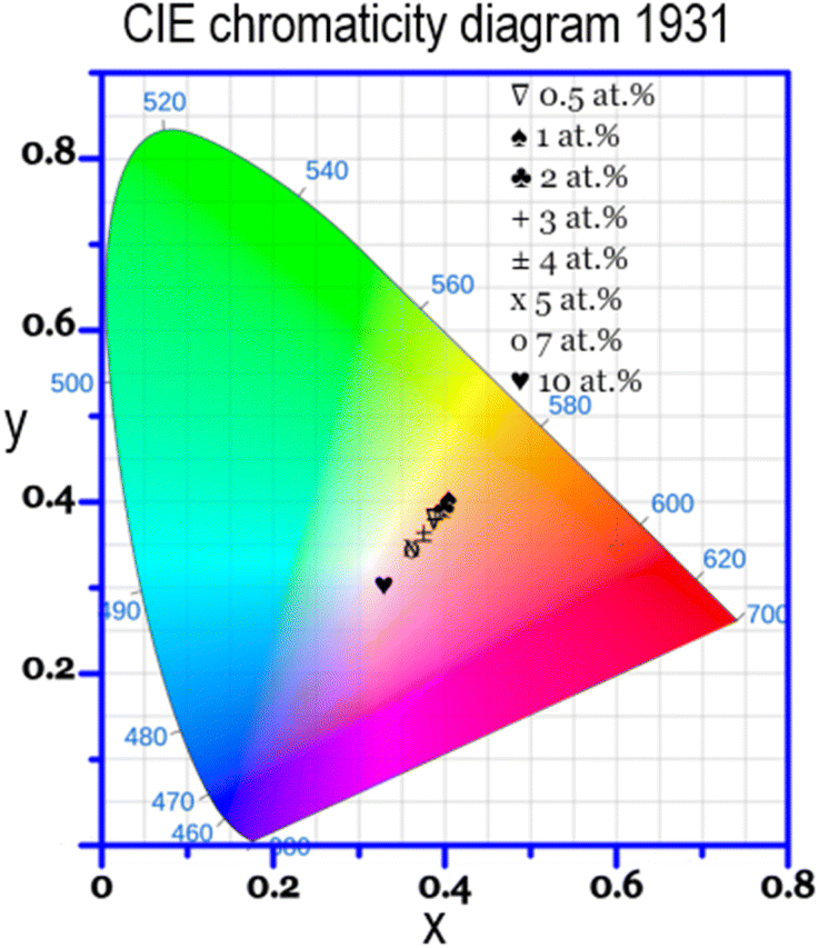 | ||
| Fig. 8 CIE color coordinates of CLSPO:Dy3+ phosphors at different Dy3+ concentrations. | ||
| Dy3+ concentration (at%) | CIE coordinates (x, y) | CCT (K) | |
|---|---|---|---|
| x | y | ||
| 0.5 | 0.405 | 0.404 | 3615.29 |
| 1 | 0.397 | 0.393 | 3712.85 |
| 2 | 0.387 | 0.380 | 3860.42 |
| 3 | 0.387 | 0.379 | 3853.19 |
| 4 | 0.374 | 0.364 | 4102.08 |
| 5 | 0.362 | 0.348 | 4376.06 |
| 7 | 0.362 | 0.346 | 4363.23 |
| 10 | 0.328 | 0.301 | 5761.52 |
Next, the fluorescence lifetime of CLSPO:Dy3+ phosphors was assessed, as illustrated in Fig. 9(a), which shows photoluminescence lifetime decay curves for CLSPO:xDy3+ with x = 0.5, 1, 2, 3, 4, 5, 7 and 10 at% at an emission wavelength of 575 nm under excitation of 345 nm. The luminescence data was fitted using a bi-exponential function as follows:22,51
I(t) = A1![[thin space (1/6-em)]](https://www.rsc.org/images/entities/char_2009.gif) exp(−t/τ1) + A2exp(−t/τ2), exp(−t/τ1) + A2exp(−t/τ2),
| (6) |
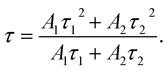 | (7) |
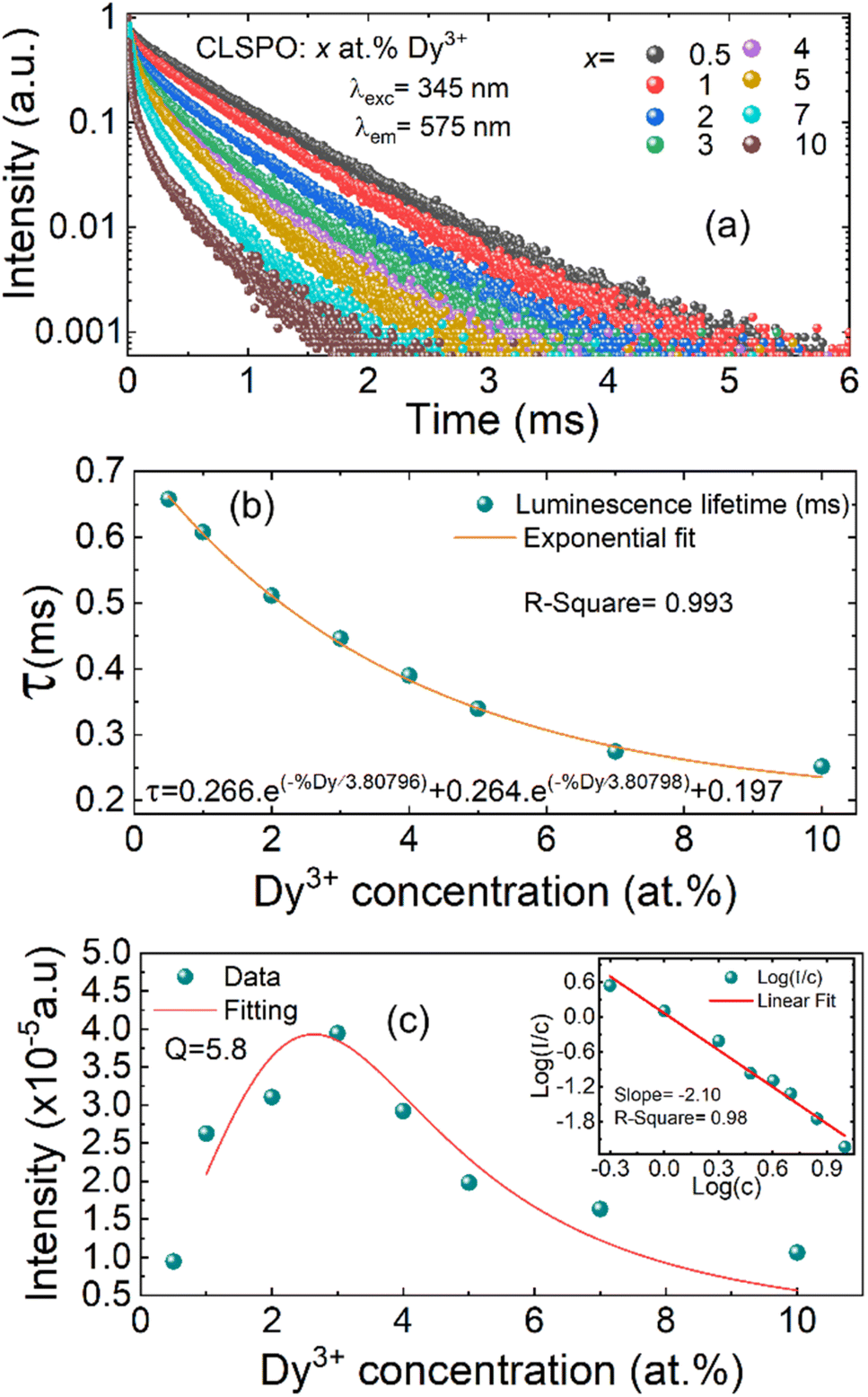 | ||
| Fig. 9 (a) Decay curves for CLSPO:xDy3+ (x = 0.5, 1, 2, 3, 4, 5, 7 and 10 at%), with excitation at 345 nm and emission at 575 nm; (b) exponential fit of the average decay lifetime to the concentration level of the Dy3+ ion; (c) variation of Y2 with Dy3+ concentration in CLSPO:Dy3+ phosphors; (the inset displays a plot of log(I/c) versus log(c)). | ||
The average lifetimes of CLSPO:x at% Dy3+ (where x = 0.5, 1, 2, 3, 4, 5, 7, and 10) are 658, 607, 511, 446, 390, 339, 274, and 252 μs, respectively. As the concentration of Dy3+ increases, the decay time significantly decreases, suggesting an increase in non-radiative transitions.5 The correlation between lifetime and doping concentration is effectively captured by the bi-exponential equation 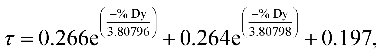 as is depicted in Fig. 9(b).
The photoluminescence behavior of Dy3+ is strongly influenced both by the local Dy3+ environment, which alters the intensity balance between yellow and blue emissions, and by the energy transfer mechanisms between Dy3+ ions, which vary as a function of concentration-dependent intensity changes. In 1967, Van Uitert established a correlation between the photoluminescence intensity of an emitter and the doping concentration, described as follows:52
 | (8) |
In 1990, Huang et al. proposed a theoretical model linking photoluminescence intensity to doping concentration, aiming to elucidate the energy transfer mechanism. According to this model, the PL intensity as a function of concentration, I(c), is expressed as:53
| I(c) = Ac(1−s/d), | (9) |
 can be modeled using eqn (9), as illustrated in the inset of Fig. 9(c). The value of the slope (s/d), determined to be 2.10 with s = 6.3, indicates that the energy transfer mechanism among Dy3+ ions in CLSPO is governed by electric dipole–dipole interactions. It is apparent that the energy transfer mechanism of Dy3+ ions in CLSPO:Dy3+ phosphors, as described by Huang's model, is consistent with Van Uitert's model.
3.4. Temperature-dependent photoluminescence properties of CLSPO:Dy3+ phosphors
The photoluminescence properties of phosphors doped with Ln3+ ions are influenced by both the energy transfer processes related to Ln3+ ion concentration and temperature-dependent non-radiative relaxation processes. As a result, the temperature-dependent evolution of photoluminescence behavior serves as an effective approach for investigating the photoluminescence mechanisms of Ln3+ ions in phosphors. Specifically, the non-radiative relaxation of electrons in Dy3+ ions occurs between the thermally coupled energy levels 4I15/2 and 4F9/2 under excitation at 445 nm, as discussed earlier.To further investigate the photoluminescence properties of CLSPO:Dy phosphors in relation to thermal effects, the photoluminescence spectra of CLSPO:3 at% Dy3+ phosphors were measured as a function of temperature. Measurements were carried out over a temperature range from 298 K to 523 K, with increments of 25 K at each step (Fig. 10(a)). It may be noted that temperature variation did not influence the photoluminescence bands. However, Y2 and B2 clearly decrease with increasing temperature, while B1 and Y1 exhibit a slight increase, where Y refers to yellow emission and B to blue emission, as shown in Fig. 10(b). On one hand, the photoluminescence intensities of Y2 and B2 exhibit a clear temperature-dependent decrease, diminishing as the temperature increases. This behavior is characteristic of standard thermal quenching of luminescence. On the other hand, the photoluminescence intensities of Y1 and B1 show an increase with rising temperature, indicating an anti-temperature quenching effect. This phenomenon is associated with enhanced temperature-dependent non-radiative relaxation processes.43
 | ||
| Fig. 10 (a) Photoluminescence spectra; (b) photoluminescence intensities of blue and yellow emissions from CLSPO:3 at% Dy3+ phosphors as a function of temperature over a temperature range from 298 K to 523 K; (c) configurational coordinate diagram illustrating the thermal quenching mechanism in CLSPO:Dy3+ phosphors; (d) evaluation of the activation energy using an Arrhenius-type activation model for CLSPO:3 at% Dy3+ phosphors. | ||
The configurational coordinate diagram serves as a valuable tool for visualizing and understanding the process of thermal quenching. This concept is effectively represented in the schematic configurational coordination model shown in Fig. 10(c). The reduction in luminescence intensity at elevated temperatures can be explained by considering the electronic transitions involved in the system. Initially, electrons in the ground state energy level are excited to higher energy states upon ultraviolet (UV) excitation at a wavelength of 445 nm. Following this excitation, a significant number of these electrons relax non-radiatively from the lowest point of the 4F9/2 and 4I15/2 energy levels back to the ground state. This transition is accompanied by the emission of intense yellow visible light, which is characteristic of the material's luminescence properties. However, due to strong interactions between phonons and electrons within the system, some excited electrons may acquire sufficient energy to overcome the Ea barrier, as indicated by route “b” in the diagram. Instead of directly relaxing radiatively, these electrons can transition into the charge transfer band (CTB) via an alternative non-radiative pathway (path “P”). Once in the CTB, they may further undergo energy dissipation through additional non-radiative processes. Eventually, electrons return to their ground state via path “g”, during which the excess energy is released in the form of thermal radiation rather than visible light emission. This process results in a decline in luminescence efficiency as temperature increases, thereby leading to the thermal quenching effect observed in the material. Ea was determined based on an Arrhenius-type activation model:54
 | (10) |
It is important to note that the photoluminescence intensities of the red emissions corresponding to the 4F9/2 → 6H11/2 and 4F9/2 → 6H9/2 + 6F11/2 transitions of Dy3+ at 661 nm and 754 nm, respectively, are smaller compared to the blue and yellow emissions, like we discussed earlier. Therefore, the color of CLSPO:xDy3+ phosphors is closely tied to the yellow and blue emissions, or more specifically, to the intensity ratio between them.
Fig. 11 shows the CIE chromaticity coordinates of CLSPO:3 at% Dy3+ phosphors, measured over a temperature range from 298 to 523 K. The inset plot at top right highlights the variations in CIE x and y coordinates as a function of temperature. The evolution of these coordinates as a function of temperature is calculated, and the corresponding values are listed in Table 5. It can be seen that color coordinates evolve almost linearly with temperature. This indicates that the ratio of intensities between the blue and yellow emissions of CLSPO:Dy3+ phosphors is intrinsically linked to temperature. The linear relationship between CIE color coordinates and temperature highlights the promising potential of CLSPO:Dy3+ phosphors for use in optical temperature sensing applications.
 | ||
| Fig. 11 CIE color coordinates for CLSPO:3 at% Dy3+ phosphors in the temperature range 298 to 523 K; the figure at top right shows the evolution of color coordinates as a function of temperature. | ||
| Temperature (K) | CIE coordinates (x, y) | |
|---|---|---|
| x | y | |
| 298 | 0.387 | 0.380 |
| 323 | 0.385 | 0.379 |
| 348 | 0.382 | 0.376 |
| 373 | 0.379 | 0.373 |
| 398 | 0.377 | 0.371 |
| 423 | 0.375 | 0.369 |
| 448 | 0.372 | 0.366 |
| 473 | 0.372 | 0.365 |
| 498 | 0.370 | 0.364 |
| 523 | 0.369 | 0.363 |
3.5. Optical temperature sensing properties of CLSPO:Dy3+ phosphors
The photoluminescence intensities Iij for the transition between energy levels i and j can be described as:| Iij = Miwijgijhvij, | (11) |
 | (12) |
 | (13) |
The contrasting behaviors of temperature-quenched Y2 and B2 emissions compared to the anti-temperature-quenched Y1 and B1 emissions, as depicted in Fig. 10(b) indicate a more pronounced variation in the luminescence intensity ratios for Y1/Y2 and B1/B2. The luminescence intensity ratios of B1/B2 and Y1/Y2 as functions of temperature are presented in Fig. 12(a) and (b), respectively. The experimental data were well fitted by eqn (13) over the temperature range 298–523 K, demonstrating the effectiveness of the optical temperature sensing capabilities. Based on eqn (11) and (12), the population of the thermally coupled upper level 4I15/2 (M3) was smaller than that of the lower thermally coupled level 4F9/2 (M2) over the entire temperature range studied. This disparity translated into a reduced probability for the 4I15/2 → 6H15/2 and 4I15/2 → 6H13/2 transitions, resulting in lower photoluminescence intensities of B1 and Y1 compared to B2 and Y2. Consequently, larger calculation errors in the luminescence intensity ratios of B1/B2 and Y1/Y2 were observed at elevated temperatures. As illustrated in Fig. 11, the temperature-dependent CIE color coordinates of synthesized CLSPO phosphors demonstrate a measurable correlation between the luminescence intensity ratio of the blue and the yellow emissions and the temperature. The luminescence intensity ratio for Dy3+ can be defined as follows:
 | (14) |
 is inadequate for assessing temperature sensing properties, as it depends only on the energy gap ΔE and does not account for the actual evolution of the intensity ratios with temperature. Therefore, the absolute sensitivity (Sa), which directly reflects how each intensity ratio changes with temperature, should be used for a more accurate comparison of the practical temperature sensing performance of the two intensity ratios (B1/B2) and (Y1/Y2) within the Dy3+-doped CLSPO phosphor system.
 | ||
| Fig. 12 Luminescence intensity ratio of (a) B1/B2, (b) Y1/Y2, and (c) Y/B in CLSPO:3 at% Dy3+ phosphors as a function of temperature; (d) Sa as a function of temperature for the three luminescence intensity ratios in CLSPO:3 at% Dy3+ phosphors. | ||
To properly assess the temperature sensing performance of CLSPO:Dy3+ phosphors, the Sa can be expressed as follows:
 | (15) |
Analogous to the definition of absolute sensitivity Sa in eqn (15), the Sa based on the luminescence intensity ratio of (Y/B) is expressed as follows:
 | (16) |
In conjunction with the thermometric characteristics derived from the three luminescence intensity ratios (B1/B2), (Y1/Y2) and (Y/B) – the absolute sensitivity Sa as a function of temperature, calculated using eqn (16), is shown in Fig. 12(d). This plot also includes the absolute sensitivities based on B1/B2 and Y1/Y2, which are computed using eqn (15).
In the temperature range examined in this study (298–523 K) for CLSPO:3 at% Dy3+ phosphors, the traditional luminescence intensity ratio of two blue emissions (B1/B2) provided the highest absolute sensitivity, while the (Y1/Y2) luminescence intensity ratio scheme showed the lowest sensitivity. The absolute sensitivity Sa based on the (Y/B) ratio decreased as temperature increased, attaining a maximum of 3.27 10−4 K−1 at 298 K and falling to 1.25 10−4 K−1 at 523 K. This indicates that Sa based on the (Y/B) ratio was higher than that of the (Y1/Y2) scheme, lower than (B1/B2), but remained in the same order of magnitude, demonstrating its effectiveness as a temperature detection method. The extended detection range, particularly at lower temperatures, is attributed to the higher Sa of the (Y/B) ratio in this region, combined with the complementary temperature dependence of the yellow and blue emissions. This ensures that the (Y/B) ratio remains responsive to temperature variations, even when individual emissions are affected by thermal quenching. It is noteworthy that thermometers based on the (B1/B2) luminescence intensity ratio have the highest absolute sensitivity.43 This is explained by the wide range of variation in the values of the luminescence intensity ratio, as described in eqn (13) and (15), compared with the (Y1/Y2) ratio. It can also be deduced from eqn (16) that the absolute sensitivity of the luminescence intensity ratio (Y/B) could be further improved by employing other techniques or adjusting the Dy3+-doped matrix to adjust the (Y/B) value.
The photoluminescence spectra of CLSPO:3 at% Dy3+ phosphors were monitored over time and during continuous cooling and heating processes to assess their repeatability and stability. As shown in Fig. 13(a), the photoluminescence intensities of B1, B2, Y1 and Y2 remained stable for at least 3 hours at different temperatures (300, 400, and 500 K). The results indicate that the emission bands exhibit minimal intensity fluctuations over time, confirming the high photostability of the phosphor. While a slight decrease in intensity is observed at elevated temperatures, the overall luminescence remains stable, demonstrating the material's resistance to thermal degradation.
 | ||
| Fig. 13 (a) The photoluminescence intensity stability at temperatures of 300, 400, and 500 K for 180 minutes and (b) the repeatability test of the luminescence intensity ratio of during heating and cooling cycles of CLSPO:3 at% Dy3+ phosphors. | ||
Repeatability (R) is a crucial parameter for evaluating the consistency of a material's performance. It can be accurately determined using eqn (17), as reported in studies:58,59
 | (17) |
4. Conclusions
In this study, we investigated the energy transfer mechanism between Dy3+ ions and introduced a new optical ratiometric thermometry strategy in Dy3+-doped CLSPO phosphors. The structural, optical, and thermometric properties of CLSPO:Dy3+ phosphors were systematically examined. X-ray diffraction and Rietveld refinement confirmed the hexagonal apatite-type structure (P63/m) with refined lattice parameters, while first-principles calculations determined a direct bandgap of 4.08 eV, supporting the suitability of CLSPO as a luminescent host material. Photoluminescence studies revealed characteristic Dy3+ emissions, with two blue bands (B1: 468 nm, B2: 479 nm) and two yellow bands (Y1: 543 nm, Y2: 575 nm). The optimal Dy3+ doping concentration was identified as 3 at%, beyond which concentration quenching effects were observed. Photoluminescence quenching analysis demonstrated that electric dipole–dipole interactions govern the dominant energy transfer mechanism. The measured absolute photoluminescence quantum yield of 5.7% confirms the optical efficiency of CLSPO:Dy3+ phosphors, while Arrhenius analysis determined an activation energy of 0.11 eV, indicating high thermal stability with minimal quenching effects. The thermometric properties of CLSPO:Dy3+ were investigated using the FIR method, demonstrating a temperature-dependent (Y/B) intensity ratio. The absolute sensitivity of the Y/B ratio was measured as 3.27 × 10⁻⁴ K−1 at 298 K, confirming the high thermometric efficiency of CLSPO:Dy3+ phosphors. Furthermore, the repeatability of the Y/B ratio exhibited a reproducibility of 95.88% at 298 K, while luminescence stability was maintained over three hours of continuous heating–cooling cycles (298–523 K), reinforcing the photostability and reversibility of the material. The proposed Y/B ratiometric approach ensures an extended temperature detection range, high accuracy, and excellent reproducibility. Its versatility enables application to other Dy3+-doped phosphors, utilizing both down- and up-conversion photoluminescence for precise sensing. The results confirm CLSPO:Dy3+ as an efficient and thermally stable material with exceptional optical performance, making it a strong candidate for advanced luminescent thermometry.Data availability
The datasets generated and analyzed during this study are not publicly available to ensure compliance with institutional policies and potential confidentiality agreements. However, they can be made available upon reasonable request. Researchers interested in accessing the data should contact the corresponding author, Dr Xavier Mateos, at E-mail: xavier.mateos@urv.cat. Requests should include a brief description of the intended use of the data and any relevant research context.Conflicts of interest
There are no conflicts of interest to declare.Acknowledgements
This publication is supported by the predoctoral program AGAUR-FI ajuts (2024 FI-1 00193) Joan Oró, which is backed by the Secretariat of Universities and Research of the Department of Research and Universities of the Generalitat of Catalonia, as well as the European Social Plus Fund. This work was also funded by grant PID2022-141499OB-100 funded by MICIU/AEI/10.13039/501100011033 and FEDER/UE. The financial support provided by the Helmholtz Association is gratefully acknowledged: (i) a Recruitment Initiative Fellowship for B. S. R.; (ii) the funding of chemical synthesis equipment from the Helmholtz Materials Energy Foundry (HEMF); and (iii) Research Field Energy – Program Materials and Technologies for the Energy Transition – Topic 1 Photovoltaics (38.01.05).References
- Z. Sun, H. Huang, R. Zhang, X. Yang, H. Yang, C. Li, Y. Zhang and Q. Wang, Nano Lett., 2021, 21, 6576–6583 CrossRef CAS PubMed.
- J. C. G. Bünzli and C. Piguet, Chem. Soc. Rev., 2005, 34, 1048–1077 RSC.
- J.-C. G. Bünzli, Acc. Chem. Res., 2006, 39, 53–61 CrossRef PubMed.
- X. Wang, Q. Liu, Y. Bu, C. S. Liu, T. Liu and X. Yan, RSC Adv., 2015, 5, 86219–86236 RSC.
- A. Douzi, S. Slimi, E. Madirov, A. Turshatov, B. S. Richards, R. M. Solé, M. Aguiló, F. Díaz, E. Ben Salem and X. Mateos, RSC Adv., 2023, 13, 23772–23787 RSC.
- M. J. Dejneka, A. Streltsov, S. Pal, A. G. Frutos, C. L. Powell, K. Yost, P. K. Yuen, U. Müller and J. Lahiri, Proc. Natl. Acad. Sci. U. S. A., 2003, 100, 389–393 CrossRef CAS PubMed.
- Y. Yan, H. Huo, H. Zhang, T. Zhao, Q. Wang, X. Zou and C. Su, J. Non-Cryst. Solids, 2021, 569, 120990 CrossRef CAS.
- Y. Lian, Y. Wang, J. Li, Z. Zhu, Z. You, C. Tu and Y.-D. Xu, Vacuum, 2020, 173, 109165 CrossRef CAS.
- L. M. Chepyga, E. Hertle, A. Ali, L. Zigan, A. Osvet, C. J. Brabec and M. Batentschuk, J. Lumin., 2018, 197, 23–30 CrossRef CAS.
- Y. Tian, B. Chen, B. Tian, Y. Mao, J. Sun, X. Li, J. Zhang, S. Fu, H. Zhong and B. Dong, J. Nanoparticle Res., 2013, 15, 1–10 Search PubMed.
- P. Babu, V. Chandrappa, N. Vijaya, C. K. Jayasankar and H. J. Seo, Phys. B, 2021, 614, 413037 CrossRef CAS.
- N. Vijaya, K. U. Kumar and C. K. Jayasankar, Spectrochim. Acta, Part A, 2013, 113, 145–153 CrossRef CAS PubMed.
- J. F. C. Carreira, N. Ben Sedrine, T. Monteiro and L. Rino, J. Lumin., 2017, 183, 251–258 CrossRef CAS.
- M. R. N. Soares, M. J. Soares, A. J. S. Fernandes, L. Rino, F. M. Costa and T. Monteiro, J. Mater. Chem., 2011, 21, 15262–15265 RSC.
- P. Suthanthirakumar and K. Marimuthu, J. Mol. Struct., 2016, 1125, 443–452 CrossRef CAS.
- T. Chengaiah, C. K. Jayasankar, K. Pavani, T. Sasikala and L. R. Moorthy, Opt. Commun., 2014, 312, 233–237 CrossRef CAS.
- N. Pawlik, T. Goryczka, E. Pietrasik, J. Śmiarowska and W. A. Pisarski, Nanomaterials, 2022, 12, 4500 CrossRef CAS PubMed.
- X. M. Zang, D. S. Li, E. Y. B. Pun and H. Lin, Opt. Mater. Express, 2017, 7, 2040–2054 CrossRef CAS.
- P. P. Pawar, S. R. Munishwar, S. Gautam and R. S. Gedam, J. Lumin., 2017, 183, 79–88 CrossRef CAS.
- Z. Cao, S. Zhou, G. Jiang, Y. Chen, C. Duan and M. Yin, Curr. Appl. Phys., 2014, 14, 1067–1071 CrossRef.
- A. R. Regmi, S. W. Allison, K. Olenick and F. Sabri, MRS Commun., 2021, 11, 322–329 CrossRef CAS.
- K. Wei, P. Li, Y. Duan, S. Zhang, L. Chen, S. Xu and J. Zhang, J. Non-Cryst. Solids, 2021, 570, 121022 CrossRef CAS.
- S. A. Wade, S. F. Collins and G. W. Baxter, J. Appl. Phys., 2003, 94, 4743–4756 CrossRef CAS.
- Z. Boruc, M. Kaczkan, B. Fetlinski, S. Turczynski and M. Malinowski, Opt. Lett., 2012, 37, 5214–5216 CrossRef CAS PubMed.
- Y. Fang, F. Liu, J. Hou, Y. Zhang, X. Zheng, N. Zhang, G. Zhao, M. Liao, G. Dai, M. Long and Y. Liu, J. Lumin., 2016, 177, 280–285 CrossRef CAS.
- M. Shang, G. Li, D. Geng, D. Yang, X. Kang, Y. Zhang, H. Lian and J. Lin, J. Phys. Chem. C, 2012, 116, 10222–10231 CrossRef CAS.
- G. Zhu, Y. Shi, M. Mikami, Y. Shimomura and Y. Wang, MRS Online Proc. Libr., 2014, 1592, 2–9 Search PubMed.
- Y. Xia, J. Chen, Y. G. Liu, M. S. Molokeev, M. Guan, Z. Huang and M. Fang, Dalton Trans., 2016, 45, 1007–1015 RSC.
- R. El Ouenzerfi, G. Panczer, C. Goutaudier, M. T. Cohen-Adad, G. Boulon, M. Trabelsi-Ayedi and N. Kbir-Ariguib, Opt. Mater., 2001, 16, 301–310 CrossRef CAS.
- Y. Wei, H. Jia, H. Xiao, M. M. Shang, C. C. Lin, C. Su, T.-S. Chan, G. G. Li and J. Lin, RSC Adv., 2017, 7, 1899–1904 RSC.
- J. Cheng, J. Zhang, X. Bian, Z. Zhai and J. Shi, Spectrochim. Acta, Part A, 2020, 230, 118057 CrossRef CAS PubMed.
- R. D. Shannon, Acta Crystallogr., Sect. A Cryst. Phys. Diffr. Theor. Gen. Crystallogr., 1976, 32, 751–767 CrossRef.
- Y. Han, S. Wang, H. Liu, L. Shi, A. Song, X. Lu, J. Wei, Z. Mao, D. Wang and Z. Mu, J. Alloys Compd., 2020, 844, 156070 CrossRef CAS.
- J. Cheng, J. Zhang, H. Zhang, S. Maryam, X. Bian, Z. Shen, X. Ni and J. Lu, Chin. Opt. Lett., 2017, 15, 121602 CrossRef.
- J. Cheng, J. Zhang, J. Lu, H. Zhang, S. Maryam, Z. Shen, X. Ni, X. Bian, P. Ma and J. Shi, Opt. Mater. Express, 2018, 8, 1850–1862 CrossRef CAS.
- G. Blasse, J. Solid State Chem., 1975, 14, 181–184 CrossRef.
- N. Lakshminarasimhan and U. V Varadaraju, J. Solid State Chem., 2004, 177, 3536–3544 CrossRef CAS.
- T. J. White and Z. Dong, Struct. Sci., 2003, 59, 1–16 CAS.
- L. Benarafa, L. Rghioui, R. Nejjar, M. S. Idrissi, M. Knidiri, A. Lorriaux and F. Wallart, Spectrochim. Acta, Part A, 2005, 61, 419–430 CAS.
- E. Rodríguez-Reyna, A. F. Fuentes, M. MacZka, J. Hanuza, K. Boulahya and U. Amador, J. Solid State Chem., 2006, 179, 522–531 CrossRef.
- J. Tauc and A. Menth, J. Non-Cryst. Solids, 1972, 8, 569–585 CrossRef.
- A. Balakrishna, V. Kumar, A. Kumar and O. M. Ntwaeaborwa, J. Alloys Compd., 2016, 686, 533–539 CrossRef CAS.
- H. Zhang, B. Cao, Z. Liao, Y. Yang, J. Zhang, L. Li, Y. Cong, Y. He, Z. Zhang, Z. Feng and B. Dong, Ceram. Int., 2022, 48, 29838–29846 CrossRef CAS.
- P. Haritha, I. R. Martín, K. Linganna, V. Monteseguro, P. Babu, S. F. León-Luis, C. K. Jayasankar, U. R. Rodríguez-Mendoza, V. Lavín and V. Venkatramu, J. Appl. Phys., 2014, 117, 174308 CrossRef.
- J. Pisarska, R. Lisiecki, W. Ryba-Romanowski, T. Goryczka and W. A. Pisarski, Chem. Phys. Lett., 2010, 489, 198–201 CrossRef CAS.
- S. Ruengsri, S. Insiripong, N. Sangwaranatee, H. J. Kim, N. Wantana, A. Angnanon and J. Kaewkhao, Integr. Ferroelectr., 2017, 177, 39–47 CrossRef CAS.
- U. Fawad, M. Oh, H. Park, S. Kim and H. J. Kim, J. Alloys Compd., 2014, 610, 281–287 CrossRef CAS.
- A. Douzi, S. Slimi, E. Madirov, M. Ghotbi, A. Turshatov, R. M. Solé, M. Aguiló, F. Díaz, E. Ben Salem and B. S. Richards, Mater. Adv., 2025, 6, 3634–3647 RSC.
- Q. Su, J. Lin and B. Li, J. Alloys Compd., 1995, 225, 120–123 CrossRef CAS.
- J. An, S. Zhang, R. Liu, G. Hu, Z. Zhang, Y. Qiu, Y. Zhou, F. Zeng and Z. Su, J. Rare Earths, 2021, 39, 26–32 CrossRef CAS.
- P. Li, Y. Lu, Y. Duan, S. Xu and J. Zhang, J. Phys. Chem. C, 2021, 125, 2382–2392 CrossRef CAS.
- L. G. Van Uitert, J. Electrochem. Soc., 1967, 114, 1048 CrossRef CAS.
- S. Huang and L. Lou, Chin. J. Lumin., 1990, 11, 1 Search PubMed.
- F. Jensen, Qual. Reliab. Eng. Int., 1985, 1, 13–17 CrossRef.
- V. Lojpur, M. Nikolic, L. Mancic, O. Milosevic and M. D. Dramicanin, Ceram. Int., 2013, 39, 1129–1134 CrossRef CAS.
- F. Men, B. Cao, Y. Cong, Y. He, Z. Zhang, Z. Feng and B. Dong, J. Lumin., 2021, 236, 118153 CrossRef CAS.
- P. Haro-González, S. F. León-Luis, S. González-Pérez and I. R. Martín, Mater. Res. Bull., 2011, 46, 1051–1054 CrossRef.
- M. Back, E. Trave, J. Ueda and S. Tanabe, Chem. Mater., 2016, 28, 8347–8356 CrossRef CAS.
- J. Rocha, C. D. S. Brites and L. D. Carlos, Chem.–Eur. J., 2016, 22, 14782–14795 CrossRef CAS PubMed.
| This journal is © The Royal Society of Chemistry 2025 |