DOI:
10.1039/D5RA02616D
(Paper)
RSC Adv., 2025,
15, 19610-19622
Robust and stable TiO2/Al2O3–SiO2 membrane with enhanced flux and antifouling performance for organic dye removal†
Received
14th April 2025
, Accepted 25th May 2025
First published on 10th June 2025
Abstract
Al2O3–SiO2 membranes were modified with a titanium source, tetrabutyl orthotitanate (TBOT), using the sol–gel method to prepare TiO2/Al2O3–SiO2 composite membranes, whose performance was tested with various ionic dyes. The membrane with nTi = 0.15 exhibited the best filtration performance, considering the rejection and membrane flux. Membrane flux was over 15% higher than that of the original membrane, whereas rejection decreased by only 2%. The experimental data were analyzed to estimate the solute transport parameter and the mass transfer coefficient (k) using the Combined Film Theory-Solution-Diffusion (CFSD) membrane transport model. The adsorption of Al2O3–SiO2 and TiO2/Al2O3–SiO2 membranes was investigated using the D–R isotherm model. It was found that cationic dyes adsorbed well on both membranes, and the adsorption binding force of the original membrane for dyes was strong, which is the reason for its poor antifouling performance. The anionic dye RB-KNB was less likely to cause membrane fouling. After six cycles of filtering the RB-KNB solution, the FRR increased from 79.9% for the original membrane to 93.8% for the modified membrane, further demonstrating that the antifouling performance of the membrane had been highly enhanced. Clearly, the obtained TiO2/Al2O3–SiO2 membrane possesses high application potential for textile wastewater treatment.
1. Introduction
Dyes are used in large quantities across a wide range of industries and water pollution caused by untreated wastewater discharged from various industries are a major environmental concern.1 Globally, nearly 700![[thin space (1/6-em)]](https://www.rsc.org/images/entities/char_2009.gif) 000 tons of dyes are consumed in various sectors, of which about 10–15% is disposed of in wastewater.2 Among the types of dyes, anionic dyes account for the largest share, ranging from 32% to 90% in wastewater.3 Although dye usage is inevitable, it greatly increases the risk of water contamination, resulting in a serious issue. The long-term benefits to human development could be profound if efficient and convenient methods are implemented to recycle water resources from dye wastewater, which is characterized by high chromaticity, significant organic content, considerable fluctuations in water quality, substantial discharge rates, and challenging treatment requirements.4
000 tons of dyes are consumed in various sectors, of which about 10–15% is disposed of in wastewater.2 Among the types of dyes, anionic dyes account for the largest share, ranging from 32% to 90% in wastewater.3 Although dye usage is inevitable, it greatly increases the risk of water contamination, resulting in a serious issue. The long-term benefits to human development could be profound if efficient and convenient methods are implemented to recycle water resources from dye wastewater, which is characterized by high chromaticity, significant organic content, considerable fluctuations in water quality, substantial discharge rates, and challenging treatment requirements.4
Numerous advanced technologies have been developed to treat dyeing effluents of varying chemical compositions. These methods can be broadly categorized into three groups: physical, chemical, and biological. Commonly used treatment technologies include flocculation/coagulation, precipitation, adsorption, membrane filtration, biological oxidation, ion exchange, and photocatalytic degradation, which vary in terms of efficiency, cost, and environmental impact. Membrane filtration can remove more contaminants than any other treatment method by preventing the passage of contaminants through physical barriers, chemical adsorption, or a combination of both. The benefits of membrane separation technology include excellent filtering purity during the separation process, minimal energy consumption, and environmental sustainability.
Compared to organic membranes, inorganic membranes have greater chemical and thermal stability, stronger resistance to fouling, higher separation efficiency, and enhanced membrane regeneration capability. Inorganic membranes are classified as carbon, zeolite, silica, ceramic, liquid, dynamic, and inorganic–organic hybrid membranes.5 SiO2 and Al2O3 monolayer ceramic membranes have been thoroughly investigated for removing dyeing solutions. Thu et al.6 used rice husk as a raw material to prepare mesoporous SiO2 for the removal of methylene blue (MB) from aqueous solutions. After 50 minutes of adsorption, the MB removal rate increased to 91.9%. The ideal dosage of SiO2 for this task was 0.05 g. In a study by Soma et al.,7 Al2O3 microfiltration membranes with a mean pore size of 0.2 μm were used to treat wastewater from the printing and dyeing industries. It was found that the addition of surfactants could increase the removal of soluble dyes by more than 97%; in a pilot test using ceramic membranes, dye removal was 80%, chemical oxygen demand (COD) removal was 40%, and membrane flux was 260–280 L m−2 h−1.
Anatase TiO2 has demonstrated promising application prospects in wastewater treatment and bactericidal self-cleaning due to its strong photocatalytic performance, large specific surface area, strong oxidizing ability and lack of secondary pollution.8 Incorporating anatase TiO2 improves the antifouling performance of Al2O3–SiO2 membranes. Additionally, the addition of TiO2 may alter the phase composition, microstructure, and surface morphology of the composite material, significantly affecting the membrane's separation ability.9 The literature10–12 reveals that the majority of research on composite membranes has been centered on aspects such as preparation methods, phase structures, pore structures, micro-morphologies, and gas separation applications. However, there has been limited investigation concerning the treatment of dye solutions. Thus, the sol–gel method was used in this work to prepare the ultrafiltration Al2O3–SiO2 composite membrane, and the doping of TiO2 modified the Al2O3–SiO2 composite membrane. Initial investigations were conducted to ascertain the filtration operating conditions of Al2O3–SiO2 and TiO2/Al2O3–SiO2 composite membranes. The applicability of the composite membranes to the filtration of dyes with varying molecular weights and ionic types was then explored. A theoretical foundation for the industrial preparation of ultrafiltration Al2O3–SiO2 and TiO2/Al2O3–SiO2 composite membranes was established using the experimental data, which made it possible to determine the filtration mechanism of ceramic composite membranes on various dyes. Additionally, the information offered a workable operational foundation for their use in the treatment of dye wastewater and other industrial domains.
2. Experimental
2.1. Chemicals
In our experiments, the raw materials included tetraethyl orthosilicate (TEOS, AR, Chengdu Kelong Chemical Reagent Factory, Chengdu, China), absolute ethanol (EtOH, AR, Tianjin Fuyu Fine Chemical Co., Ltd, Tianjin, China), nitric acid (HNO3, AR, Sichuan Xilong Chemical Co., Ltd, Sichuan, China), aluminium isopropoxide (AIP, AR, Chengdu Kelong Chemical Reagent Factory, Chengdu, China), N,N-dimethylformamide (DMF, AR, Tianjin Kemiou Chemical Reagent Co., Ltd, Tianjin, China), tetrabutyl orthotitanate (TBOT, AR, Tianjin Kemiou Chemical Reagent Co., Ltd, Tianjin, China).
2.2. Fabrication of sols
2.2.1. Fabrication of SiO2 sols. The samples were prepared by the sol–gel method with TEOS as the silicon source, EtOH as the solvent, and HNO3 as the catalyst. The molar ratio of TEOS/EtOH/H2O/HNO3 was controlled at 1/3.8/5/0.085. TEOS and EtOH were mixed to form a homogeneous solution and stirred for 40 min at room temperature. Subsequently, H2O and HNO3 were added dropwise to the homogenous solution of TEOS and EtOH. After rapidly stirring the mixture and refluxing it for 3 h at 60 °C, the translucent and colorless SiO2 sol was obtained.
2.2.2. Fabrication of Al2O3 sols. AIP was used as the aluminum source and HNO3 as the catalyst. The molar ratio of AIP/H2O/HNO3 was controlled to be 1/100/0.25. Three flasks containing deionized water were heated to 80 °C. AIP, which was ground into powder in advance, was slowly added to deionized water, fully hydrolyzed for 1.5 h, and then HNO3 was gradually added. At 85 °C, the mixture was aggressively stirred, refluxed for 8 h, and then cooled to obtain a pale blue Al2O3 sol.
2.2.3. Fabrication of TiO2 sols. The molar ratio of TBOT/EtOH/H2O/HNO3 was 1/50/4/0.2. TBOT was first added to EtOH and thoroughly dissolved by stirring it for 30 min at 30 °C. Then, the mixture of H2O and HNO3 was added dropwise to the homogeneous solution of TBOT and EtOH, stirred vigorously for 2 h, and cooled naturally to obtain a light yellow transparent TiO2 sol.
2.2.4. Fabrication of TiO2/Al2O3–SiO2 sols. According to the Al/TEOS molar ratio (nAl) of 0.3, the obtained Al2O3 sol was added dropwise to the SiO2 sol diluted with absolute ethanol in this work and mixed thoroughly at room temperature for 40 min. Next, in accordance with different Ti/TEOS molar ratios, the prepared TiO2 sol was added dropwise to the Al2O3–SiO2 sol. The TiO2/Al2O3–SiO2 composite sol was obtained by fully mixing for 40 min at room temperature. The molar ratios of Ti/TEOS (nTi) are 0, 0.03, 0.08, 0.1 and 0.3, respectively.
2.3. Fabrication of unsupported TiO2/Al2O3–SiO2 materials
The prepared TiO2/Al2O3–SiO2 composite sol was dried in a vacuum drying oven at 40 °C and then ground into a fine powder with an onyx mortar to obtain the TiO2/Al2O3–SiO2 gel material. Finally, the gel material was heated to 350 °C at a heating rate of 0.5 °C min−1 in a tube furnace, kept for 2 h, and then cooled naturally to obtain the TiO2/Al2O3–SiO2 unsupported body membrane material.
2.4. Fabrication of TiO2/Al2O3–SiO2 membranes
The pretreated α-Al2O3 composite disc support was immersed in the TiO2/Al2O3–SiO2 sol diluted with 3 times ethanol for 6 s and withdrawn at a rate of 10 cm min−1. After dip coating, the membrane support was placed in a drying oven with a vacuum degree of −0.08 MPa and a temperature of 30 °C for 2 h and then placed in a tube furnace for roasting. The calcination process was the same as that of the unsupported membrane material, and calcining temperature was increased to 350 °C at a rate of 0.5 °C min−1 and maintained for 2 h. The four-time repetitions, with natural cooling, can be done to minimize the defects caused by dust in the air; thus, the TiO2/Al2O3–SiO2 composite membrane can be obtained. The preparation process of the TiO2/Al2O3–SiO2 membrane material is shown in Fig. 1.
 |
| | Fig. 1 Schematic of the preparation process for TiO2/Al2O3–SiO2 sols/materials/membranes. | |
2.5. Characterization
Fourier transform infrared spectroscopy (FTIR) was used to analyze the functional groups of the membrane materials before and after modification by the KBr pressing method. The spectral measurements were conducted over a wavelength range of 400 to 4000 cm−1. X-ray diffraction (XRD) analysis was conducted on a Rigaku D/max 2200 diffractometer, employing CuKα radiation (40 kV, 40 mA) to ascertain the chemical compositions of the materials, with a scanning range of 5° to 85° at a rate of 5° per minute. N2 adsorption–desorption tests were performed on the membrane materials before and after modification using a specific surface area and pore size analyzer. N2 was used as the adsorbate, dehydrated at 90 °C for 1.5 h, degassed at 250 °C for 6 h, and then tested in an instrument with a liquid nitrogen temperature of 77 K. The surface morphologies of the membranes were examined using a scanning electron microscopy (SEM, JEOL JSM-6300, Hitachi, Tokyo, Japan) operated at an accelerating voltage of 5 kV, with secondary electron signals acquired through an Everhart–Thornley detector. The contact angle tests were carried out using a contact angle goniometer (CA, JY-82, China). A laser particle size analyzer was used to evaluate the zeta potential of sols at 25 °C, and the average value was calculated after three measurements. BSD-500 platinum–cobalt colorimeter was used to detect the chroma before and after dye filtration.
2.6. Adsorption properties
Four dyes were selected to test the adsorption performance of the TiO2/Al2O3–SiO2 membrane: cationic dye neutral red (NR, AR, relative molecular weight (Mw) = 288.78, λmax = 533 nm) and methylene blue (MB, AR, relative molecular weight (Mw) = 373.90, λmax = 664 nm), anionic dye reactive black KNB (RB-KNB, AR, Relative molecular weight (Mw) = 991.82, λmax = 206 nm) and non-ionic dye disperse navy blue HGL (DNB-HGL, BS, relative molecular weight (Mw) = 799.80, λmax = 225 nm). NR, MB and RB-KNB were purchased from Tianjin Kemiou Chemical Reagents Co., Ltd and DNB-HGL was purchased from Zhejiang Boao New Materials Co., Ltd.
The adsorbent and dye solution were poured into a conical flask, and the adsorption process was carried out at a constant temperature in a water bath shaker. After centrifuging the supernatant at a low speed, an ultraviolet-visible spectrophotometer was used to measure its absorbance. The linear equation of dye labelling was used to calculate the concentration after adsorption, and then the adsorption capacity (qe) and adsorption rate were calculated according to eqn (1):
| |
 | (1) |
where
C0 and
Ce (mg L
−1) are the initial and equilibrium concentrations of the dye, respectively.
W (g) is the dry mass of the xerogels.
V (L) is the volume of the solution.
2.7. Filtration properties
The filtration performance of the membrane was evaluated at 25 °C using a cross-flow separation system. The filtration performance of the TiO2/Al2O3–SiO2 composite membrane was investigated with respect to the effects of the coating layer number, nTi value, pressure and dye molecular weight. Additionally, the filtration mechanisms of TiO2/Al2O3–SiO2 composite membranes for the four dyes were further investigated.
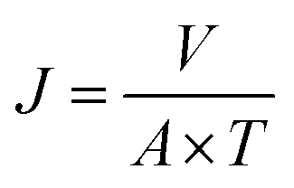
The membrane flux and rejection rate of an inorganic membrane reflect its filtration and separation performance, while the flux indicates the fluid transmission rate. The membrane flux represents the total amount of liquid after passing through a certain membrane area at a certain time. The calculation eqn (2):
| |
 | (2) |
Here,
J (L m
2 h
−1) represents membrane flux.
A (m
2) is the effective area of the membrane.
T (h) is the transit time.
V (L) is the liquid volume.
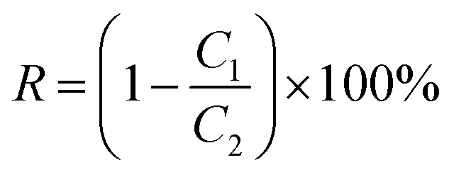
The rejection rate reflects the separation effect of the fluid after passing through the membrane. The effect of membrane interception is often quantified in percentage form by measuring the ratio of the solute concentration in the solution before and after membrane filtering. Eqn (3) is as follows:
| |
 | (3) |
where
R (%) represents the retention rate.
C1 (mol L
−1) represents the concentration of the permeate component.
C2 (mol L
−1) represents the feed component concentration.
2.8. Estimation of membrane transport parameters using the CFSD model
The membrane theory is widely used to estimate the solute transport parameter DAM × K/δ and mass transfer coefficient k in the membrane. The Combined Film Theory-Solution-Diffusion (CFSD) model combines the dissolution-diffusion model with the along-membrane theory.13 The current working equation for the CFSD model is given as eqn (4).14 DAM × K/δ and k have important effects on the rejection and membrane flux. DAM × K/δ is an important index of membrane transport performance, which reflects the diffusion and transport capacity of the solute in the membrane. In general, the larger the parameter DAM × K/δ, the easier it is for the solute to pass through the membrane, which may lead to a decrease in the rejection rate. k describes the mass transfer rate of the solute in the boundary layer of the membrane surface. The larger k indicates that the mass transfer rate of the solute in the boundary layer is fast, which enables the solute to reach the membrane surface more quickly. This, in turn, facilitates the solute to pass through the membrane, which may increase the membrane flux. The relationship data between Ro and Jv, obtained by each group under constant feed concentration, constant feed rate and different pressures, can be used to numerically estimate the values DAM × K/δ and k. Plotting graph ln((1 − Ro) × Jv/Ro) vs. Jv, where ln(DAM × K/δ) is the intercept and 1/k is the slope, allows one to determine ln(DAM × K/δ) and k.| |
 | (4) |
where Ro (%) is rejection. Jv (m s−1) is the membrane flux. K is the partition coefficient. DAM (m2 s−1) represents the diffusion coefficient of the solute in the membrane. δ (m) is the thickness of the membrane. k (m s−1) is the mass transfer coefficient. DAM × K/δ (m s−1) is a comprehensive parameter referred to as the solute transport parameter.
Eqn (5) is obtained by differentiating eqn (4) with respect to Jv and setting this derivative to zero.
Here,
Jv,min is the minimum value when
Ro is the maximum.
2.9. Dye pollution resistant evaluation
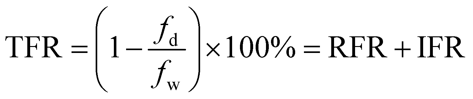
The cationic NR and anionic RB-KNB were used as organic pollutants to determine the antifouling performance of the optimal membranes. The following is the filtration process: first, after 30 min of filtering pure water, the pure water flux of freshly made membranes (fw) was determined. The dye solution was then filtered for 2 h to determine the membrane filtration performance, which was represented by dye flux (fd). After that, pure water recovery flux (fr) was calculated by rinsing the filter membrane with pure water for 30 min. One filtration cycle was defined as filtering the dye solution for 2 h and pure water for 30 min. Flux recovery rate (FRR), total flux decline rate (TFR), reversible flux decline rate (RFR), and irreversible flux decline rate (IFR) were used to assess the antifouling performance of the membrane. These parameters are calculated using the following formulas (6)–(9):15| |
 | (6) |
| |
 | (7) |
| |
 | (8) |
| |
 | (9) |
3. Results and discussion
3.1. Phase-chemical structure analysis
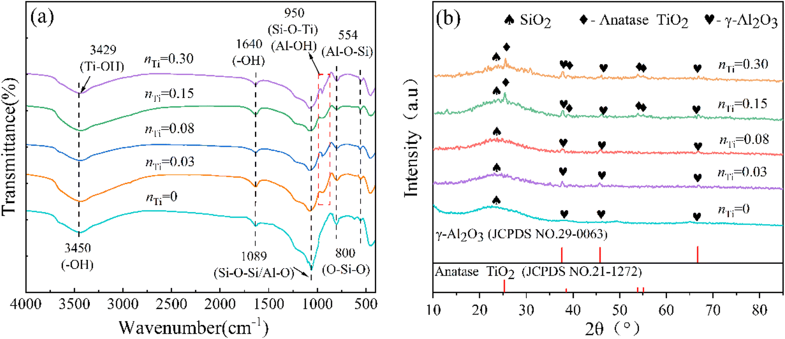
The infrared spectra of unsupported TiO2/Al2O3–SiO2 materials modified by different TiO2 doping contents are shown in Fig. 2(a). A peak of absorption is seen in all TiO2/Al2O3–SiO2 materials at 3450 cm−1, which is associated with the –OH stretching vibration of the surface-adsorbed water and structural coordination water.16 The hydroxyl groups (O–H) on the surface of TiO2 are responsible for the band at 3429 cm−1. The bending vibration peak of –OH in the physically adsorbed water is reflected by an absorption peak at 1640 cm−1.17 The absorption peak of the TiO2/Al2O3–SiO2 material at 1089 cm−1 is the binding peak of Si–O–Si and Al–O bonds. The two absorption peaks are similar and overlap each other. Furthermore, in the TiO2/Al2O3–SiO2 material, the Si–O–Ti bond stretching vibration peak was observed at 950 cm−1 in contrast to the Al2O3–SiO2 material.18 For octahedrally coordinated Al, the vibration of the Al–OH bonding can be attributed to the band in the 937–980 cm−1 range.19 In contrast to a straightforward physical van der Waals force, the formation of the Si–O–Ti bond suggests that the bond between TiO2 and SiO2 is the result of a chemical reaction process. The symmetric stretching vibration peak of the Si–O bond appears at 800 cm−1. After combining SiO2 and Al2O3 sols, the reaction between Si–OH and Al–OH groups occurs, which allows some Si and Al atoms to be substituted for one another to form Si–O–Al bonds. The peak is ascribed to around 554 cm−1.20 In addition, due to the dehydroxylation reaction during the curing process, a more stable oxygen bridge bond was formed, and an absorption peak of Ti–O–Al–O–Si was speculated to be in the region of 500–1000 cm−1. The hydrothermal stability of the material is enhanced by the presence of Al–O–Si and Ti–O–Al–O–Si bonds. It can be seen from the diagram that the FTIR curve shape and the position of each absorption peak of the TiO2/Al2O3–SiO2 membrane materials with different nTi are roughly similar, but the intensity of individual absorption peaks changes. With the increase of nTi, the stretching vibration peak of the Si–O–Ti bond at 950 cm−1 increases, and the antisymmetric stretching vibration peak of the Si–O–Si bond at 1089 cm−1 and the O–Si–O symmetric stretching vibration peak at 800 cm−1 decrease. As the concentration of nTi increases, there is a notable enhancement in the stretching vibration peak of the Si–O–Ti bond at 950 cm−1. Conversely, the antisymmetric stretching vibration peak of the Si–O–Si bond at 1089 cm−1 and the symmetric stretching vibration peak of the O–Si–O bond at 800 cm−1 exhibit a marked decrease.
 |
| | Fig. 2 (a) FTIR spectra and (b) XRD patterns of unsupported TiO2/Al2O3–SiO2 materials with different nTi. | |
Fig. 2(b) illustrates the XRD patterns of unsupported TiO2/Al2O3–SiO2 materials with different TiO2 doping contents. TiO2/Al2O3–SiO2 materials have a broad diffraction peak at about 2θ = 23.40°, corresponding to amorphous SiO2.21,22 Three characteristic diffraction peaks of γ-Al2O3 (JCPDS 29-0063) appeared near 2θ = 37.60°, 45.78°, and 66.76° for each membrane material, and the corresponding crystal plane indexes were (311), (400), and (440), respectively. When the TiO2 doping content is small and nTi = 0.03 and 0.08, the curve shape and position of the diffraction peaks are roughly similar due to the low TiO2 doping content or due to its reaction with SiO2, which could be the possible reason for no characteristic diffraction peak of anatase TiO2 in the XRD spectra of the two TiO2/Al2O3–SiO2 materials. When nTi = 0.15 and 0.3, the characteristic diffraction peaks of anatase TiO2 (JCPDS21-1272) appeared near 2θ = 25.28°, 38.58°, 53.89° and 55.06° in the XRD patterns of TiO2/Al2O3–SiO2 materials, and the corresponding crystal planes were (101), (112), (105) and (211), respectively. With the increase of nTi, the intensity of these diffraction characteristic peaks increased. It can be speculated that when nTi ≥ 0.15, the phase structure of the TiO2/Al2O3–SiO2 material is mainly composed of amorphous SiO2, γ-Al2O3 and anatase TiO2.
3.2. Pore structure analysis
The specific surface area and pore structure of TiO2/Al2O3–SiO2 membranes with varying nTi were investigated using the N2 adsorption–desorption and pore size analysis processes. Their N2 adsorption–desorption isotherms are shown in Fig. 3(a). It is clear that the form of the N2 adsorption–desorption isotherm curves for all unsupported TiO2/Al2O3–SiO2 materials is nearly identical. At a relative pressure P/P0 < 0.1, the N2 adsorption capacity of the membranes rapidly increases due to the high adsorption potential energy within the pores. Consequently, the adsorption capacity of N2 continues to increase gradually while the relative pressure rises. The N2 adsorption–desorption isotherms of the TiO2/Al2O3–SiO2 materials exhibit hysteresis loops, which IUPAC classifies as class IV isotherms with H4 hysteresis loops, suggesting that the materials are typical microporous structures. The adsorption capacity of N2 rises as nTi increases, improving the N2 adsorption performance. The reduction in the adsorption amount of N2 at nTi = 0.3 may be caused by pore collapse and shrinking of the internal pore structure of the TiO2/Al2O3–SiO2 material.
 |
| | Fig. 3 (a) N2 adsorption–desorption isotherms and (b) pore size distributions of unsupported TiO2/Al2O3–SiO2 membrane materials with different nTi. | |
Fig. 3(b) shows the pore size distribution of unsupported TiO2/Al2O3–SiO2 membranes with different nTi. The diagram illustrates a difference in the pore size distribution of the Al2O3–SiO2 material. When nTi becomes larger, the maximum micropore volume of the TiO2/Al2O3–SiO2 material is mainly concentrated at 1.09–2.00 nm. It reveals that as nTi increases, the pore size distribution of the TiO2/Al2O3–SiO2 material changes significantly. As the pore size distribution broadens, the average pore size increases, the pore size distribution moves to a wider pore range, and there is a tendency from micropore distribution to mesopore distribution.
Table 1 displays the pore structure characteristics of the membranes with varying nTi. It can be seen that after Ti element doping, with the increase of nTi, the average pore size, micropore volume, total pore volume, micropore surface area and BET surface area of the TiO2/Al2O3–SiO2 membrane material increase. Because in the TiO2/Al2O3–SiO2 membrane material, part of TiO2 is uniformly covered on the surface of SiO2 or into the pores of SiO2 with smaller particles, which will increase the micropore surface area and BET-specific surface area of the membrane material. The average pore size of the membranes, on the other hand, increases as a result of Ti atoms taking the lattice position of Si atoms and creating a new skeleton Si–O–Ti when some TiO2 replaces some SiO2 in the network. More anatase TiO2 crystals are formed and distributed on the surface of the SiO2 network when nTi = 0.3. The internal pore structure of the TiO2/Al2O3–SiO2 membrane material is blocked and shrinkage and pore collapse occur, resulting in a decreased total pore volume and BET-specific surface area. Therefore, combining the above analyses, it can be seen that more TiO2 doping is not necessarily better; rather, the smaller the TiO2 doping, the larger the microporous surface area and microporous volume percentage, the more suitable it is for filtration studies.
Table 1 Pore structure parameters of TiO2/Al2O3–SiO2 membrane materials with different nTi
| nTi |
BET surface area/m2 g−1 |
Micropore area/m2 g |
VT/cm3 g |
VMic/cm3 g−1 |
Mean pore width/nm |
| 0 |
216.427 |
102.762 |
0.130 |
0.062 |
2.348 |
| 0.03 |
181.904 |
100.796 |
0.107 |
0.037 |
2.334 |
| 0.08 |
241.771 |
143.504 |
0.149 |
0.089 |
2.405 |
| 0.15 |
278.962 |
178.240 |
0.166 |
0.110 |
2.468 |
| 0.3 |
202.853 |
110.191 |
0.113 |
0.065 |
2.555 |
3.3. SEM analysis
Fig. 4 shows the surface electron micrographs of the membranes, respectively. The surface of the two composite materials is relatively flat, with a uniform coating, and there are no visible cracks and gaps, indicating that the coating and roasting processes are better. The Al2O3–SiO2 sol was successfully dip-coated on the α-Al2O3 support. The particle size was between 0.9 and 6.3 nm. Compared with the Al2O3–SiO2 membrane, the surface particle size distribution of the TiO2/Al2O3–SiO2 composite membrane is wider, and the particle size is between 1 and 7.8 nm. Small white particles are observed on the surface of the membrane, possibly TiO2 not entering the SiO2 network structure and covering the surface of the membrane. The TiO2/Al2O3–SiO2 sol was successfully impregnated on the α-Al2O3 support, with a part of the sol penetrating into the support.
 |
| | Fig. 4 SEM images of surfaces of (a) Al2O3–SiO2 and (b) TiO2/Al2O3–SiO2 membranes. | |
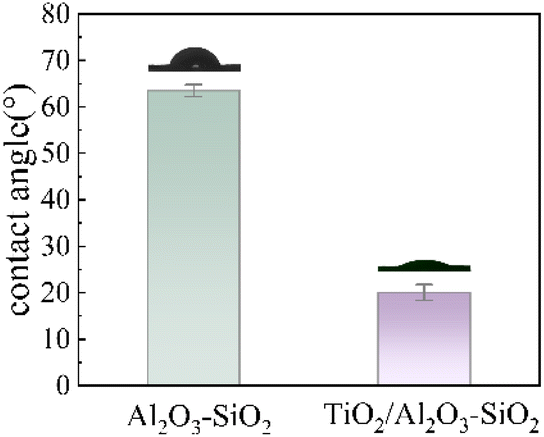
3.4. Contact angle test
The pure water contact angle test was carried out to judge the hydrophilicity of the modified membrane. From Fig. 5, the water contact angles of Al2O3–SiO2 and TiO2/Al2O3–SiO2 membranes are 63.5° and 20.1°, respectively. It can be seen that with the addition of TiO2, the water contact angle decreases, indicating that the hydrophilicity of the modified membrane is enhanced, which helps water to pass through the membrane more easily during the filtration process.23
 |
| | Fig. 5 Contact angle of Al2O3–SiO2 and TiO2/Al2O3–SiO2 membranes. | |
3.5. Filtration performance analysis
3.5.1. Effect of the coating layer number. In this experiment, the number of coating layers was used to determine membrane thickness. Fig. 6 depicts the particular impact of the number of coating layers on the RB-KNB rejection and membrane flux in the composite membrane. It is evident that for the same membrane, under similar conditions, the rejection rate of the RB-KNB solution rises and the membrane flux falls with the increase in the number of coating layers. This is because when the number of coating layers is small, holes and cracks appear on the surface or in the deeper layers of the calcined ceramic membrane, resulting in a large membrane flux and a low rejection rate. As the number of coating layers increases, the sol particles will repair the cracks and defects that may exist on the surface of the film. However, when the coating layer is 7, the membrane layer becomes thicker and denser, the membrane flux decreases, and the rejection rate is not significantly higher. An excellent ceramic membrane should have both a large membrane flux and a good rejection rate. Based on the evaluation of the two, the five-layer coating membrane is more in line with the experimental requirements.
 |
| | Fig. 6 (a) Membrane flux and (b) rejection of the TiO2/Al2O3–SiO2 membrane for separation of RB-KNB at different coating layers (conditions: initial dye concentration = 50 mg L−1, contact time = 2 h, T = 298 K, and pressure = 0.2 MPa). | |
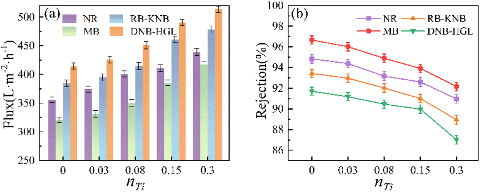
3.5.2. Effect of nTi. Fig. 7 illustrates the influence of nTi on flux and rejection. The membrane material exhibits a greater rejection rate for cationic dyes (NR and MB) and a higher membrane flux for anionic and nonionic dyes. The membrane flux increased rapidly as the nTi increased, but the rejection of dyes by TiO2/Al2O3–SiO2 reduced gradually. Through the FTIR and N2 adsorption–desorption analysis of the membranes, it can be known that a new skeleton Si–O–Ti is formed in the TiO2/Al2O3–SiO2 membrane owing to the introduction of TiO2, increasing the average pore size of the membrane material.24
 |
| | Fig. 7 Effect of nTi on the (a) membrane flux and (b) rejection of the TiO2/Al2O3–SiO2 composite membrane (conditions: initial dye concentration = 50 mg L−1, contact time = 2 h, T = 298 K, and pressure = 0.2 MPa). | |
As the nTi increases, the average pore size of the TiO2/Al2O3–SiO2 membrane material becomes larger, allowing dye solutions to pass through the membrane surface faster, resulting in an increased membrane flux and a reduced rejection rate. It is very important to choose an optimal TiO2 doping ratio for further research. Considering the removal rate and membrane flux, nTi = 0.15 is found to be more suitable.
3.5.3. Effect of pressure difference. Fig. 8(a) shows the effect of pressure difference at 25 °C on the filtration of RB-KNB by Al2O3–SiO2 and TiO2/Al2O3–SiO2 composite membrane. Fig. 8(a) depicts the effect of a pressure variation at 25 °C on the filtration of RB-KNB by Al2O3–SiO2 and TiO2/Al2O3–SiO2 composite membranes. The rejection rate of the composite membrane to RB-KNB increased first and then decreased with increasing pressure, reaching its peak at 0.2 MPa. Also, the membrane flux of the TiO2/Al2O3–SiO2 membrane is better than that of the Al2O3–SiO2 membrane because as the pressure increases, concentration polarization becomes stronger and plays a leading role.
 |
| | Fig. 8 Effect of (a) pressure difference and (b) dye molecular weight on the rejection rate by Al2O3–SiO2 and TiO2/Al2O3–SiO2 composite membranes (conditions: initial dye concentration = 50 mg L−1, contact time = 2 h, and T = 298 K). | |
When the pressure reaches a specific level, the operational pressure plays a leading role, resulting in a progressive reduction in the rejection rate. In addition, as the pressure increases, the membrane flux gradually increases, but the increase is significantly reduced. When the external pressure is low, dye molecules begin to deposit on the membrane surface or penetrate the membrane pores, causing lighter fouling. However, as the pressure increases, more dye molecules are trapped and a boundary layer forms, reducing the increase in membrane flux.
3.5.4. Effect of dye molecular weight. The interception of the membrane and the adsorption and permeation of dye molecules on the membrane surface are responsible for the effect of the dye molecular weight on the performance of membrane filtration of dye wastewater. According to Fig. 8(b), the rejection rates of TiO2/Al2O3–SiO2 composite membranes for the four dyes were in the order of MB > NR > RB-KNB > DNB-HGL, with rejection rates of 93.92%, 92.61%, 91.01%, 89.98%, respectively, and the removal rates of composite membranes for the four dyes did not follow the pattern of the higher molecular weights of the dyes.Detection of chroma before and after membrane filtration of dye wastewater is one of the commonly used methods to evaluate the treatment effect of dye wastewater. The chroma rejection rates of NR, MB, RB-KNB and DNB-HGL by TiO2/Al2O3–SiO2 composite membrane were 99.76%, 98.23%, 97.61% and 95.16%, respectively. In conclusion, the TiO2/Al2O3–SiO2 composite membrane has an excellent effect on color removal in dye solutions.
3.6. Membrane transport parameter analysis
The experimental data were analyzed using the CFSD model. Fig. 9 shows the curves of the corresponding models of RB-KNB, that is, the relationship between ln((1 − Ro) × Jv/Ro) and Jv. The parameters k and DAM × K/δ were determined from the plot. From Table 2, the parameters DAM × K/δ and k of the TiO2/Al2O3–SiO2 membrane are larger than those of the Al2O3–SiO2 membrane, indicating that the RB-KNB can migrate more quickly in the TiO2/Al2O3–SiO2 membrane, reducing the accumulation in the membrane and helping to maintain a higher flux. The model predicts the maximum rejection rate Ro,max at the minimum flux Jv,min. The results indicate that the TiO2/Al2O3–SiO2 membrane has great potential in removing dyes from wastewater.
 |
| | Fig. 9 CFSD model of RB-KNB onto Al2O3–SiO2 and TiO2/Al2O3–SiO2 membranes. | |
Table 2 Parameter estimated using the data-fitting method for RB-KNB
| Membrane |
K × 102 (cm s−1) |
DAM × K/δ × 104 (cm s−1) |
Jv,min × 102 (cm s−1) |
Ro,max |
| TiO2/Al2O3–SiO2 |
2.720 |
7.888 |
2.720 |
0.99 |
| Al2O3–SiO2 |
1.335 |
3.453 |
1.335 |
0.99 |
3.7. Antifouling performance analysis
In this study, the D–R model was used to explore the strength of the adsorption between the membrane material and the dyes, and to estimate the adsorption energy. In the D–R model, the adsorption process is primarily driven by pore filling, with the adsorbent's porosity considered a critical factor that influences this mechanism.25 Fig. 10(a and b) presents the nonlinear fitting results of the D–R isothermal adsorption models, while Table 3 summarizes the corresponding characteristic parameters. The calculation of the D–R model is described using eqn (10)–(12):| |
 | (11) |
| |
 | (12) |
Here, qm (mg g−1) is the theoretical saturation capacity. ε is the Polanyi potential. E (kJ mol−1) is the average adsorption energy. KD is the constant related to the mean free energy of adsorption.
 |
| | Fig. 10 D–R isotherm model of dyes onto (a) TiO2/Al2O3–SiO2 and (b) Al2O3–SiO2 membranes; (c) long-time separation performance of the membrane for filtration of RB solution; (d) anti-pollution parameters of TiO2/Al2O3–SiO2 and Al2O3–SiO2 membranes; and cyclic separation flux of the prepared membranes for (e) RB and (f) NR. | |
Table 3 D–R isotherm parameters for dye adsorption under 298 K
| Membrane |
Parameters |
NR |
MB |
RB-KNB |
DNB-HGL |
| TiO2/Al2O3–SiO2 |
qm (mg g−1) |
25.28 |
26.29 |
18.32 |
12.17 |
| E |
5.737 |
5.722 |
2.685 |
2.643 |
| Al2O3–SiO2 |
qm (mg g−1) |
31.71 |
32.49 |
22.76 |
16.51 |
| E |
6.070 |
7.661 |
3.216 |
3.044 |
As indicated in Table 3, the theoretical saturated adsorption capacity qm of the Al2O3–SiO2 membrane for the four dyes is all larger than that of the TiO2/Al2O3–SiO2 membrane. In addition, the average adsorption energy E obtained from the D–R model analysis can provide information on the adsorption mechanism and physical or chemical processes. The adsorption behavior was ascribed to physical and ion exchange processes when the E values were within the range of 1–8 kJ mol−1 and 8–16 kJ mol−1, respectively, and E values greater than 16 kJ mol−1 are regarded as corresponding to chemical adsorption.26 As presented in Table 3, the Al2O3–SiO2 membrane exhibits higher E values compared to the TiO2/Al2O3–SiO2 membrane. Furthermore, the E values of both membranes for cationic dyes are significantly higher than those for other dye types. The higher adsorption energy implies that a more stable combination is formed between the adsorbate and the adsorbent. To some extent, the stability of the adsorption performance of the adsorbent is ensured by the fact that the adsorbate is difficult to fall off its surface when it is disturbed by external factors. However, it is easy to cause serious membrane fouling, shorten the service life of the membrane, and thus greatly increase the operating cost.
The long-term separation performance of the RB-KNB solution filtration for up to 20 h was utilized to assess the separation stability of the TiO2/Al2O3–SiO2 membrane, as shown in Fig. 10(c). After 2 h, the membrane separation property was basically stable. The permeability and rejection of the TiO2/Al2O3–SiO2 membrane remained relatively constant during the long-term separation process. Also, it has better stability than the Al2O3–SiO2 membrane. This result indicates that the TiO2/Al2O3–SiO2 membrane has stable separation performance. The experimental results reveal that the TiO2/Al2O3SiO2 membrane has good permeability, rejection, and antifouling capabilities while filtering anionic dye solutions.
A membrane with strong antifouling performance can significantly enhance separation efficiency and minimize the number of cleaning steps, thereby significantly extending its service life.27 This study evaluated the antifouling capabilities of the recently developed TiO2/Al2O3–SiO2 membrane by filtering the RB-KNB and NR solutions. Fig. 10(d) shows the antifouling parameters of the modified membrane and the original membrane, including FRR, RFR, and IFR. From the initial evaluation of the resistance to fouling of both membranes, it is clear that TiO2 improves the overall resistance of the membrane to fouling, as evidenced by the higher FRR values than uncoated membranes. In general, the flux decline can be explained by two main aspects: the reversible fouling effect and irreversible fouling effect. Although both reversible and irreversible fouling can affect the membrane performance, the former can be ‘reversed’ more easily with the help of a simple hydraulic cleaning method, while the latter often requires a large number of chemical cleaning operations or direct membrane replacement. It can be seen that irreversible fouling is the main factor leading to membrane performance degradation and life reduction. The results in Fig. 10(d) indicate that the NR dye has a higher level of pollution to the Al2O3–SiO2 membrane, as reflected by the larger IFR value and lower FRR value. For filtered RB-KNB and NR solutions, there was an increase in FRR from 79.9% to 93.8% and from 59.1% to 82.6%, respectively; also, the decrease in IFR was from 20.1% to 6.2% and from 40.9% to 17.4%, respectively. This could be attributed to the hydroxyl groups on the surface of the TiO2 nanoparticles, which increase the hydrophilicity of the membrane surface and thus the resistance to fouling.28,29 TiO2 can improve the hydrophilicity of the membrane and reduce membrane fouling, which has been widely reported.30 These improvements represent a significant advancement in the antifouling abilities of ceramic membranes containing TiO2. In addition, the adsorption energy (E) calculated from the D–R curve indicates that the TiO2/Al2O3–SiO2 membrane fouling is mainly caused by physical adsorption, which makes it easier to remove anionic dyes. The TiO2/Al2O3–SiO2 membrane exhibits the lowest TFR value after filtering the RB-KNB solution, and the RFR is higher than IFR, which verifies the previous conclusion.
In general, the cycle performance test demonstrates the stability of the membrane and its ability to withstand long-term operation. Therefore, the selected membranes were subjected to 6 cycles of RB-KNB and NR filtration, with 2.5 h per cycle. Fig. 10(e) and (f) display the findings of the reusability investigation. At the end of the sixth cycle, the flux of TiO2/Al2O3–SiO2 to RB-KNB and NR solutions decreased by 30.9% and 62.6%, respectively, while the flux of Al2O3–SiO2 decreased by 66.0% and 81.5%, respectively. Although the cleaning method may not completely restore the surface of the membrane, TiO2 ensures better antifouling performance of the TiO2/Al2O3–SiO2 membrane, and the flux loss is lower than that of the unmodified Al2O3–SiO2 membrane.
3.8. Filtration mechanism analysis
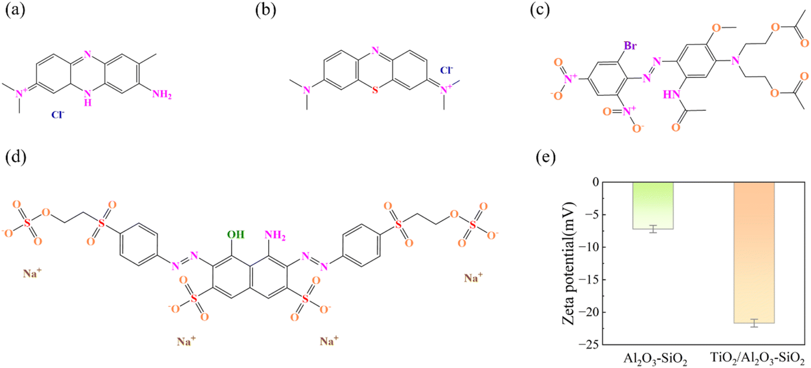
The filtration of NR, MB, RB-KNB and DNB-HGL by Al2O3–SiO2 and TiO2/Al2O3–SiO2 composite membranes is not a simple screening mechanism. The nature of the dye, its molecular structure, and the charge interaction between the dye and the membranes all affect the different ways the membrane rejects dyes.31
The rejection rate of the composite membranes to the four dyes does not follow the rule that rejection rates increase with molecular weight. Fig. 11(a–d) is the molecular structure diagram of the four dyes, and Fig. 11(e) shows the surface charge properties of the two membranes under neutral pH conditions. NR dyes, on the one hand, comprise a phenazine chloride group with a cyclic molecular structure and high rejection rate. On the other hand, NR is a cationic dye that carries a positive charge in aqueous solutions due to the presence of N+ ions. There are two types of interactions between composite membranes and the NR solution. One is electrostatic interactions with N+ ions, and the other is adsorption caused by van der Waals forces. The composite membranes mainly intercept NR through pore size screening, physical adsorption and electrostatic interaction. The filtration mechanism of MB is similar to that of NR. The RB-KNB has more water-soluble groups and better water solubility. It is an anionic dye, and the aqueous solution is negatively charged, which is mutually exclusive with the negative charges on the two membranes, reducing the speed of dye molecules passing through the membranes and resulting in high rejection. In addition, due to the enhanced hydrophilicity and low surface roughness of the TiO2/Al2O3–SiO2 membrane, there is electrostatic repulsion between the dye and the membrane surface, which greatly reduces the amount of dye adsorbed on the membrane surface.32 The filtration mechanism is mainly mechanical interception and adsorption interception. Studies have shown that the electrostatic repulsion between the dye molecules and the membrane surface can enhance the rejection performance of the membrane for the same charge dye, inhibit the adsorption of the dye, and improve its antifouling properties.33 Fig. 12 shows the filtration mechanism of RB-KNB on the surface of Al2O3–SiO2 and filtration TiO2/Al2O3–SiO2 membranes. DNB-HGL is an azo dye with poor water solubility. It is a non-ionic dye, and the surface charge of the composite membranes does not affect it. The N and O atoms and aromatic rings in the dye structure have hydrogen bonds with the surface of the material. Therefore, the filtration mechanism is mainly based on mechanical interception and adsorption interception, and the interception rate is low. The average adsorption energy (E) of the Al2O3–SiO2 membrane to the four dyes is more powerful, as can be observed from the D–R curve, suggesting a stronger binding effect between the membrane and the dyes. Therefore, it is speculated that there are hydrogen bonds between the Al2O3–SiO2 material surface and the dye structure.34 The TiO2/Al2O3–SiO2 composite membrane exhibited high and stable water permeability to both anionic and non-ionic dyes and remarkable resistance to fouling. It is clear that there is competitive potential for water treatment with the composite membranes made in this work.
 |
| | Fig. 11 Molecular structures of (a) NR, (b) MB, (c) DNB-HGL, and (d) RB-KNB and (e) zeta potential of Al2O3–SiO2 and TiO2/Al2O3–SiO2 membranes. | |
 |
| | Fig. 12 Filtration mechanism of RB-KNB on the surface of (a) Al2O3–SiO2 and (b) TiO2/Al2O3–SiO2 composite membranes. | |
As shown in Table 4, we compare our work with other reported studies. The TiO2/Al2O3–SiO2 composite membrane exhibits excellent water permeability for dyes and maintains a high rejection rate for organic dyes. It demonstrates that the composite membrane prepared in this work has competitive potential in water treatment.
Table 4 Literature review on modified membranes for separation of dyes
| Membrane |
Flux (L m−2 h1) |
Dye rejection (%) |
FRR |
Testing condition |
Ref. |
| PVDF/CD-0.75/25 |
75.2 |
CR (99%) |
97.6% (BSA, after 5 cycles) |
4 bar |
35 |
| PPSU/P(D2-AE1) |
222 |
CR (99.9%) |
96.2% (BSA) |
1 bar |
36 |
| Zeolite-A/polystyrene |
93.51 |
DR 80 (99%) |
94.6% (DR 80) |
3 bar |
37 |
| TiO2@ZIF-67/PVDF |
261.4 |
RB (97.4%) |
56.2% (BSA) |
2 bar |
38 |
| PANI–TiO2/PVDF |
88 |
RB (81.5%) |
95% (BSA) |
2 bar |
39 |
| Ag@chitosan/PPSU |
227.48 |
RB (89.27%) |
86.13% (BSA) |
2 bar |
40 |
| Fe3O4@SiO2@PrEDAS |
358.6 |
RB (97%) |
>70% (BSA) |
2 bar |
41 |
| RR 120 (99%) |
| PES–MF |
82.7 |
RB (99.76%) |
67.72% (RB) |
4 bar |
42 |
| Sepro NF 2A |
19.5 |
NR (88.7%) |
— |
2 bar |
43 |
| CA/GO–TiO2 membrane |
31.8 |
MB (99.3%) |
76.01% (BSA) |
0.9 bar |
44 |
| PS/SiO2 membrane |
9.1 |
MB (90.1%) |
— |
4 bar |
45 |
| TiO2/Al2O3–SiO2 membrane |
461.3 |
RB (91.0) |
88.72% (RB, after 6 cycles) |
2 bar |
This study |
| 490.2 |
DB (89.9) |
— |
| 411.1 |
NR (92.6%) |
74.32% (NR, after 6 cycles) |
| 385.6 |
MB (93.9%) |
— |
4. Conclusions
This work effectively prepared TiO2/Al2O3–SiO2 composite membranes using the sol–gel method to remove various ionic forms of organic dyes from water. Various analyses, such as N2 adsorption–desorption, FTIR, XRD and SEM, were used to evaluate the fabricated composite membranes. FTIR analysis confirmed the presence of anionic hydroxyl groups in the membrane structure, facilitating interactions with the cationic dyes. Filtration experiments revealed that the average pore size of the TiO2/Al2O3–SiO2 membrane material increased with nTi, leading to a rise in membrane flux and a drop-in rejection rate. Considering the combined rejection rate and flux, the optimal filtration performance of the membrane appeared at nTi = 0.15. The CFSD model analysis of the experimental data suggests that the TiO2/Al2O3–SiO2 membrane is more conducive to dye molecule transport, which reduces the risk of solute accumulation and clogging on the membrane surface to some extent, and the separation efficiency of the membrane is relatively high. The antifouling experiment revealed that the anionic dye RB-KNB is less likely to cause membrane fouling on the material, decreases membrane flux slightly, and has a high flux recovery rate. The FRR and IFR values of the TiO2/Al2O3–SiO2 membrane increased by 17.4% and decreased by 69.1%, respectively, after 6 cycles of filtering the RB-KNB dye, compared to the original membrane. The modified membrane maintains its separation stability for 20 h. The incorporation of TiO2 improves the antifouling capabilities of the Al2O3–SiO2 composite membrane, making this study extremely promising in the field of green and sustainable environmental governance. Future research could focus on expanding the applicability of membranes to pollutants, conducting simultaneous antibacterial performance testing, and improving their reusability by optimizing regeneration methods.
Data availability
All relevant data are included within the paper. All data supporting the findings of this study are available within the paper and its ESI.†
Author contributions
Qi Deng: conceptualization, methodology, formal, and writing. Jing Yang: funding acquisition and review & editing. Yuzhi Ai: project administration.
Conflicts of interest
The authors declare that they have no known competing financial interests or personal relationships that could have appeared to influence the work reported in this paper.
Acknowledgements
This work was supported by the Key Research and Development Projects of Shaanxi Province, China [2024GX-YBXM-491], the Nature Science Basic Research Plan in Shaanxi Province, China [2024JC-YBMS-361] and the Xi'an Municipal Science and Technology Project, China [23GXFW0023].
References
- R. J. Ganaie, S. Rafiq and A. Sharma, IOP Conf. Ser. Earth Environ. Sci., 2023, 1110, 012040 CrossRef
 .
. - A. N. M. A. Haque, R. Remadevi, X. Wang and M. Naebe, Mater. Today: Proc., 2020, 31, S221–S226 CAS .
- A. M. A. Haque, N. Sultana, A. M. Sayem and S. A. Smriti, Sustainability, 2022, 14, 11098 CrossRef CAS .
- J. W. Yoon, M. H. Baek, J. S. Hong, C. Y. Lee and J. K. Suh, Korean J. Chem. Eng., 2012, 29, 1722–1729 Search PubMed .
- A. K. Fard, G. McKay, A. Buekenhoudt, H. Al Sulaiti, F. Motmans, M. Khraisheh and M. Atieh, Materials, 2018, 11, 74 Search PubMed .
- H. T. Thu, L. T. Dat and V. A. Tuan, Vietnam J. Chem., 2019, 57, 175–181 Search PubMed .
- C. Soma, M. Rumeau and C. Sergent, Proc. 1st Intl. Conf. Membranes, Montpellier, 1989, pp. 523–526 Search PubMed .
- S. Banerjee, D. D. Dionysiou and S. C. Pillai, Appl. Catal., B, 2015, 176–177, 396–428 CrossRef CAS .
- Z. Zeng, X. Xiao, Z. Gui and L. Li, Mater. Lett., 1998, 35, 67–71 Search PubMed .
- M. L. Sun, T. B. Zhao, Z. F. Li, Z. F. Ma, J. Wang and F. Y. Li, Ceram. Int., 2016, 42, 15926–15932 Search PubMed .
- X. Xu, Y. Zhang, J. Wu and Z. Bai, J. Wuhan Univ. Technol., Mater. Sci. Ed., 2003, 18, 15–19 CAS .
- J. Liu, Y. Li, B. Yin, S. Li and P. Chen, Int. J. Appl. Ceram. Technol., 2022, 20, 371–379 CrossRef .
- Z. V. P. Murthy and S. K. Gupta, Sep. Sci. Technol., 1996, 31, 77–94 Search PubMed .
- J. Babu and Z. V. P. Murthy, Sep. Purif. Technol., 2017, 183, 66–72 CrossRef CAS .
- L. Shamaei, P. Karami, B. Khorshidi, R. Farnood and M. Sadrzadeh, ACS Sustainable Chem. Eng., 2021, 9, 15768–15779 CrossRef CAS .
- Q. M. Ahkam, E. U. Khan, J. Iqbal, A. Murtaza and M. T. Khan, Phys. B Condens. Matter., 2019, 572, 161–167 CrossRef CAS .
- J.-S. Jeng, L.-L. Yang and J. Chen, Thin Solid Films, 2017, 640, 20–26 CrossRef CAS .
- R. Dalmis, N. F. A. Azem, I. Birlik and E. Çelik, Appl. Surf. Sci., 2019, 475, 94–101 CrossRef CAS .
- A. Adamczyk and E. Długoń, Spectrochim. Acta, Part A, 2012, 89, 11–17 CrossRef CAS PubMed .
- J. Yang, Z. Xu, R. Mu, Y. Zhao, B. Li and H. Hou, Integr. Ferroelectr., 2020, 207, 220–230 Search PubMed .
- U. Anggarini, L. Yu, H. Nagasawa, M. Kanezashi and T. Tsuru, Mater. Chem. Front., 2021, 5, 3029–3042 RSC .
- M. Sadeghi, G. Khanbabaei, A. H. S. Dehaghani, M. Sadeghi, M. A. Aravand, M. Akbarzade and S. Khatti, J. Membr. Sci., 2008, 322, 423–428 CrossRef CAS .
- L. Han, J. Ma, H. Lin, C. Chen, J. Teng, B. Li, D. Zhao, Y. Xu, W. Yu and L. Shen, Chem. Eng. J., 2023, 470, 144311 Search PubMed .
- J. Yang and Q. Liang, Ferroelectrics, 2019, 547, 10–20 CrossRef CAS .
- M. E. Mahmoud, M. F. Amira, S. M. Seleim and A. K. Mohamed, J. Chem. Eng. Data, 2017, 62, 839–850 CrossRef CAS .
- D. Cheng, J. Chen, J. Wang and X. Liu, Heliyon, 2023, 9, e15979 CrossRef CAS PubMed .
- Y. Shi, X. Chen, Q. Wu, H. Zhen, S. Wang, H. Dong, J. Wang and Y. Li, J. Environ. Chem. Eng., 2023, 11, 110389 CrossRef CAS .
- S. S. Madaeni, S. Zinadini and V. Vatanpour, J. Membr. Sci., 2011, 380, 155–162 CrossRef CAS .
- S. S. Madaeni and N. Ghaemi, J. Membr. Sci., 2007, 303, 221–233 CrossRef CAS .
- X. Zhang, Z. Wang, M. Chen, M. Liu and Z. Wu, J. Membr. Sci., 2016, 520, 66–75 CrossRef CAS .
- J. Hou, Y. Chen, W. Shi, C. Bao and X. Hu, Appl. Surf. Sci., 2020, 505, 144145 CrossRef CAS .
- C. Wang, W. Zhang, C. Zhang, H. Xu, L. Liu and C. Zhang, J. Membr. Sci., 2022, 663, 121061 CrossRef CAS .
- L. Xiao, L. Chen, H. Xu, Z. Huang, Z. Wang, F. Liu, W. Wang and Q. Du, RSC Adv., 2025, 15, 9141–9152 RSC .
- S. E. Gavabari, A. Goudarzi, M. Shahrousvand and A. Asfaram, Sep. Purif. Technol., 2024, 330, 125285 CrossRef .
- Y. Wang, C. Bao, D. Li, J. Chen, X. Xu, S. Wen, Z. Guan, Q. Zhang, Y. Ding, Y. Xin and Y. Zou, J. Membr. Sci., 2022, 661, 120925 CrossRef CAS .
- F. Dai, G. Qian, Z. Ke, K. Xu, M. Wang, D. Li, Z. Deng, Y. Yu and C. Chen, Sep. Purif. Technol., 2024, 345, 127403 CrossRef CAS .
- A. Essate, D. El Machtani Idrissi, B. Achiou, S. Adlane, M. Breida, S. Curcio, S. Chakraborty, S. A. Younssi and M. Ouammou, Colloids Surf., A, 2024, 703, 135162 CrossRef CAS .
- N. Prabhakar, A. M. Isloor, M. Padaki and A. F. Ismail, Chem. Eng. J., 2024, 498, 155270 CrossRef CAS .
- V. R. Pereira, A. M. Isloor, A. K. Zulhairun, M. N. Subramaniam, W. J. Lau and A. F. Ismail, RSC Adv., 2016, 6, 99764–99773 RSC .
- I. M. Kolangare, A. M. Isloor, Z. A. Karim, A. Kulal, A. F. Ismail, Inamuddin and A. M. Asiri, Environ. Chem. Lett., 2019, 17, 581–587 Search PubMed .
- V. Vatanpour, S. Soylu, D. Osman, G. Tuncay, A. Mobaraki, Z. Marjani, A. Z. Halimehjani and I. Koyuncu, J. Environ. Chem. Eng., 2024, 12, 113308 Search PubMed .
- A. A. Neto, E. F. D. Januário, R. Bergamasco and A. M. S. Vieira, Environ. Nanotechnol. Monit. Manag., 2024, 22, 100954 CAS .
- W. Y. Ye, J. Y. Lin, R. Borreg, D. Chen, A. Sotto, P. Luis, M. H. Liu, S. F. Zhao, C. Y. Tang and B. Van der Bruggen, Sep. Purif. Technol., 2018, 197, 27–35 CrossRef CAS .
- Y. C. Liu, Z. X. Yu, Y. X. Peng, L. Y. Shao, X. H. Li and H. J. Zeng, Chem. Phys. Lett., 2020, 749, 137424 CrossRef CAS .
- W. D. Ding, H. W. Zhuo, M. T. Bao, Y. M. Li and J. R. Lu, Chem. Eng. J., 2017, 330, 337–344 CrossRef CAS .
|
| This journal is © The Royal Society of Chemistry 2025 |
Click here to see how this site uses Cookies. View our privacy policy here. 
 Open Access Article
 This Open Access Article is licensed under a Creative Commons Attribution-Non Commercial 3.0 Unported Licence
 a,
Jing Yang*a and
Yuzhi Aib
a,
Jing Yang*a and
Yuzhi Aib