DOI:
10.1039/D5RA00613A
(Paper)
RSC Adv., 2025,
15, 15086-15107
Predictive modeling of pulse-electrodeposited Cu–Zn alloy and dealloying for porous electrode fabrication†
Received
26th January 2025
, Accepted 6th April 2025
First published on 8th May 2025
Abstract
Porous metals (PMs) have attracted significant attention in recent years due to their unique structural and functional properties, holding potential for a wide range of applications in catalysis, sensing, energy storage, and filtration. Among these, porous copper (PC), which is produced by dealloying copper–zinc (Cu–Zn) alloys has evolved as a particularly valuable material. In this study, a Cu–Zn alloy is electrochemically deposited onto a Cu wire in a sulphate-based electrolyte containing tri-sodium citrate as a complexing agent. To produce PC, the alloy has been subjected to chemical dealloying to dissolve the less noble element. We have implemented machine learning algorithms such as adaptive neuro-fuzzy inference systems (ANFIS), artificial neural networks (ANN), and response surface methodology (RSM) to model the interaction of process parameters and responses. Statistical modeling has been carried out to investigate the influence of operating parameters, including precursor reagent quantities (0.002–0.2 M), electrodeposition time (15–45 min), and dealloying time (16–24 h), on Zn content, dealloyed weight, and change in grain size. The test results confirm that both models fit the experimental data well, with the ANN model achieving high accuracy (R2 = 0.98, 0.96, and 0.96 for Zn content, dealloyed weight, and grain size change, respectively); however, the ANFIS model demonstrates superior performance with the highest R2 value (0.99) and the lowest MAPE (0.003, 0.002, and 0.001 for the respective responses). The RSM-BBD model is best suited for analyzing parameter interactions on responses, as it systematically evaluates the combined effects of multiple variables. By using potentiodynamic polarization curves to compare the corrosion resistance of Cu–Zn electrodes to bare Cu and PC electrodes, it was found that Cu–Zn electrodes have better corrosion resistance. Additionally, dealloying has resulted in a transition from a hydrophobic (110 ± 1°) to a hydrophilic (59 ± 0.5°) surface.
1 Introduction
Porous metals (PMs), a form of micro- or nanostructured materials, have unique features that make them extremely promising for a variety of applications, including catalysis, sensors, energy storage devices, microfluidic devices, microactuators, fuel cells, and batteries.1–5 Due to their extremely high specific area open nanostructure, high electrical conductivity, and enhanced mass transfer qualities, these metals exhibit distinctive chemical and physical characteristics. A small-scale structure on a surface has been demonstrated in several tests to considerably increase the heat transmission coefficient and decrease wall superheating. PMs have so far been manufactured using a variety of techniques, such as gas bubbling, foaming, melt gas injection, vapor deposition techniques, selective metal electrodeposition, powder sintering, and dealloying.6,7 The dealloying method is based on the selective dissolution of the initially alloyed element that is more chemically reactive. In contrast to traditional techniques such as gas bubbling foaming or powder sintering, the process of dealloying entails the deliberate extraction of one or more constituents from an alloy, resulting in the formation of a porous structure. This procedure provides a high degree of control over the size, distribution, and structure of pores, leading to the creation of PMs with features that are perfectly tuned. In addition, the process of dealloying obviates the necessity for intricate and costly apparatus, rendering it a financially viable and ecologically sustainable substitute. Dealloying was first investigated as an electrochemical phenomenon linked to alloy corrosion, but it has lately gone beyond electrochemistry and been established as a reliable and ubiquitous technique for producing functional porous materials.8,9 Dealloyed PMs can be tuned to have characteristic lengths between a few nanometers and tens of micrometers and porosities between 30–80%, which both easily satisfy the structural demands of the most of energy storage devices.10 To dealloy binary alloys into isotropic, bicontinuous, porous structures, the beginning alloy must have perfect single-phase solid solubility.11 Crack-free dealloyed porous films are necessary because the cracking phenomenon inhibits numerous applications. Cracking is caused primarily by the mechanical stress induced by substantial changes in volume of up to 30% as a result of the dealloying procedure. By varying the electrolyte and dealloying time, it is possible to control the various microstructure evolution characteristics of np-material obtained during dealloying. The chemical dealloying method was utilized to manufacture porous patterns of various metal compositions, including gold (Au), platinum (Pt), palladium (Pd), silver (Ag), nickel (Ni), lead (Pb), and copper (Cu).12–17
Numerous studies have investigated the development of porous-Au from Ag–Au alloy, while extensive research has also been conducted on Pt-based np materials such as np-Pt and np-Au–Cu–Pt coatings as promising catalysts for applications in fuel cells. Dealloyed NP-Cu film has garnered significant attention in the field of materials science due to its low density, high modulus of elasticity, and low production cost. In addition, porous Cu exhibits exceptional characteristics for applications including catalysis, sensors, energy storage, and electrochemical applications.18,19 Porous copper (PC) can be formed through the process of dealloying several binary alloys, such as Ti–Cu,20 Zn–Cu,21 Mn–Cu,22 Mg–Cu,23 Ag–Cu24 and Al–Cu.25
Electrodeposition is a non-vacuum electrochemical process that is highly preferred for deposition of thin films due to its ability to deposit multicomponent alloys at room temperature. Due to its simplicity and affordability in contrast to other methods of deposition, electrodeposition has proven to be a technique with widespread industry acceptance.26–29 The electrodeposition of Cu–Zn alloys mandates the use of coordinating agents to reduce the significant variation in the reduction potentials of Cu2+ and Zn2+, which are +0.337 V and −0.76 V, respectively. Since the potential difference is 1.104 V between Cu–Zn, many researchers have added complexing agents such as: cyanide, pyrophosphate, sorbitol, EDTA, triethanolamine, tartrate, sodium citrate, etc. in electrolyte solution to reduce the electrochemical reactivity of Cu2+ ions. Vivegnis et al.30,31 presented two studies in that they have fabricated Cu–Zn alloys electrodeposition with TEA and pyrophosphate as a complexing agent to make Cu–Zn precursor films for subsequent dealloying. Tuan et al.32 reported that crack-free NP-Cu films were synthesized by electrochemical deposition of Cu–Zn alloy films by chronoamperometry at 0.5 V (Ag/AgCl), followed by a two-step (in NaOH, and HCl solutions) chemical dealloying process. Du et al.33 employed seignette salt (NaKC4H4O6) as a complexing agent to electrodeposit Cu–Zn alloys in alkaline conditions and then produced the porous copper foil by chemically dealloying in NaOH 2 wt% for 15 h, followed by 20 s in HCl 4.0 mol L−1. Ibrahim et al. explored the acidic and alkaline dealloying procedures of Zn80Cu20 alloy ribbons via melt spinning process. They discovered that changing the type of the electrolyte solution, pH value, dealloying duration, and temperature can alter the structure of the nanostructure.
To the best of literature review conducted by authors, there is a lack of research work exploring the concentration of Cu and Zn required to produce either a Zn-rich or Cu-rich alloy. Surface morphology, physical and chemical properties can be altered by adjusting the electrolyte concentration, pH, deposition duration, applied voltage, and other parameters. Manually investigating the influence of electrodeposition and dealloying parameters, as well as recognizing the relationship between output parameters, is extremely challenging.34 A possible strategy is to use soft computing artificial intelligence (AI) technologies such as artificial neural network (ANN), adaptive neuro-fuzzy inference systems (ANFIS), and response surface methodology (RSM) to identify the effect of experimental parameters on dependent variables. As an AI model, an ANN exhibits the ability to decipher complex and multivariate industrial processes using algorithms that replicate the functioning of the human neural system. Such systems are used in this model to simulate, process, forecast, and optimize the reactions of many engineering application.35–37 ANFIS is a hybrid AI model that combines the natural benefits of neural networks with fuzzy logic in interpreting complicated processes with low steady-state error.38 ANFIS operates by adaptively generating fuzzy controllers and constructing separate rules that augment its self-learning capability. Design of experiments (DOE) is a sophisticated numerical and statistical tool for solving multi-factor engineering problems.39 It is driven by the need to reduce experimental volume, costs, time, and physical resources. Being an advanced DOE technique, RSM uses statistical concepts to build models and analyze processes.
In the presented study, we have developed the PC substrate prepared via dealloying of Zn from Cu–Zn electrodeposited alloy. The Cu–Zn alloy and PC were analyzed using FESEM for surface morphology, EDS for elemental composition, corrosion resistance and hydrophobicity. The objective is to accurately model and predict responses with ANN, ANFIS, and RSM models to establish a relationship between experimental parameters (Cu and Zn concentration in electrolyte, electrodeposition time, and dealloying time) and experimental responses (Zn content, dealloyed weight, and percentage change in average grain size). These AI models have not been described previously to predict the above responses based on performance data previously. We also compared the two AI models to the RSM model using evaluation parameters.
2 Materials & methods
Copper sulphate pentahydrate (CuSO4·5H2O, 98%), zinc sulphate heptahydrate (ZnSO4·7H2O, 99.5%), sodium sulphate (Na2SO4, 99%), saccharin (C7H5NO3S, 98%) were purchased from Sigma-Aldrich, New Delhi, India. Tri sodium citrate (Na3C6H5O7, 99%), boric acid (H3BO3, 99.5%), sodium hydroxide pallets (NaOH, 99.5%), and hydrochloric acid (HCL, 38%) were purchased from Thermo Fisher Scientific Pvt. Ltd, Mumbai, India. All the chemicals were utilized without being purified further.
2.1 Electrodeposition parameters and setup
The electrolyte was prepared by mixing (0.002–0.02 M) CuSO4·5H2O, (0.1–0.2 M) ZnSO4·7H2O, and (0.4 M) H3BO3 which was added to maintain the pH and to decrease the hydrogen evolution. (0.2 M) Na3C6H5O7 was used as complexing agent, (0.01 M) C7H5NO3S was added to the solution to reduce internal stress by providing a sufficient crystallization, (0.16 M) Na2SO4 was used as supporting electrolytes in sulphate bath medium.
A function generator (Siglent, SDG 1032X), a digital storage oscilloscope (Rigol, MSO2102A), a hot plate and a magnetic stirrer (Cole-Parmer, 30–550 °C, 0–1100 rpm), a cathode, an anode, and an electrolyte solution comprise the electrodeposition experimental setup (Fig. 1). The anode is a copper strip measuring 3 × 1 cm2, while the cathode is a 1 mm diameter and 3 cm in length copper wire that acts as the deposition location. The surface of both electrodes is prepared by grounding them with different grit grades of sandpaper, followed by a cloth polishing phase. Following polishing, the electrodes are immersed in ethanol for 10 minutes and subjected to ultrasonic cleaning. To remove any adherent particles, the electrodes are rinsed with acetone and deionized (DI) water. The pulsed electrodeposition carried out using the above mentioned in-house experimental setup, during the process pulse frequency, duty cycle, bath temperature, and bath agitation were kept constant at 100 Hz, 40%, 40 °C, and 300 rpm, respectively.
 |
| | Fig. 1 Schematic of pulse electrodeposition experimental setup for Cu–Zn deposition. | |
2.1.1 Dealloying. Prior to dealloying, Cu–Zn electrodes were rinsed with DI water at room temperature and ethanol using an ultrasonic bath. The electrodeposited coatings were dealloyed by immersing them in 1.3 M NaOH for 16–24 hours and then in 0.1 M HCl for 20 seconds. HCl was used to remove copper oxide, to facilitate the formation of micro/nano structures.40 After various dealloying times, treated samples were removed from the solution, washed with DI water, dried in an Ar atmosphere, and either used immediately for more studies or stored under vacuum to prevent air oxidation. The weighing balance (Shimadzu) was used to weigh electrodes before and after dealloying, and the dealloyed weight was calculated using the equation below:| | |
Dealloyed weight (mg) = Wtbefore − Wtafter
| (1) |
2.2 Statistical modelling
2.2.1 RSM Box–Behnken. In this work, Box–Behnken design of RSM (RSM-BBD) was applied to model the experiment using Design-Expert software version 11. To estimate the variables in order to optimize and analyze the weight deposition during electrodeposition, dealloyed weight, and percentage changes in average grain size, RSM-BBD was used. Furthermore, four independent process factors, copper sulphate concentration, zinc sulphate concentration, electrodeposition time, and dealloyed time, were studied to determine optimal conditions and correlations between the desired outcomes. Individual variables were allocated to one of three levels: lower, medium, and upper ranges of −1, 0, and +1, respectively. The process parameters and their factors and ranges are given in Table 1:
Table 1 Operating parameters employed and their range and coded values
| Factors |
Parameters |
Units |
Coded low |
Coded mean |
Coded high |
| −1 |
0 |
+1 |
| A |
Copper sulphate concentration |
Mol |
0.002 |
0.011 |
0.02 |
| B |
Zinc sulphate concentration |
Mol |
0.1 |
0.15 |
0.2 |
| C |
Electrodeposition time |
Minutes |
15 |
30 |
45 |
| D |
Dealloying time |
Hours |
16 |
20 |
24 |
The investigations in response surface methodology using BBD for optimization were formulated and arranged by utilizing a mathematical eqn (2) (ref. 41) given below:
where,
N is the total number of experiments run,
P is the number of process parameters (
P = 4), and
Cp is the center points chosen (
Cp = 5). The polynomial regression equation serves as a tool to elucidate the intricate interplay between independent variables and corresponding responses. In order to address a second-order polynomial problem, the empirical data presented in
Table 2 underwent analysis
via the response surface regression methodology. The mathematical representation of this model is encapsulated within the quadratic second-order regression polynomial
eqn (3), as expressed below:
| |
 | (3) |
where
Ri denotes the response values (deposited weight, dealloyed weight, change in average grain size),
i and
j signify the factors identified as independent variables, represented as coded values. The constant or offset term is indicated as
b0, whereas
bi is a linear parameter,
bii, and
bij, is an interaction parameter, and
xi,
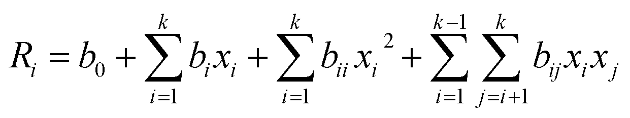
xj are independent process variables. The ANOVA (analysis of variance) approach was used to determine the interaction between the independent factors and the output responses. Following that, 2D or 3D dimensional contour plots were used to visualize these interactions.
Table 2 Experimental design matrix and response based on actual and predicted response of zinc content, dealloyed weight, and percentage change in average grain size values suggested by ANN, ANFIS, and RSM-BBD design
| Run |
Cu sulphate conc. |
Zn sulphate conc |
Electrode-position time |
Dealloying time |
Zinc content before dealloying |
ANN |
ANFIS |
DOE |
Dealloyed weight |
ANN |
ANFIS |
DOE |
% Change in average grain size |
ANN |
ANFIS |
DOE |
| S-1 |
0.011 |
0.15 |
15 |
16 |
30 |
30 |
30.00 |
33.54 |
1.8 |
1.80 |
1.80 |
1.65 |
75 |
80.42 |
75.00 |
74.58 |
| S-2 |
0.002 |
0.15 |
30 |
24 |
41 |
41 |
41.00 |
48.38 |
4.2 |
4.20 |
4.20 |
4.24 |
84 |
84.00 |
84.00 |
85.50 |
| S-3 |
0.011 |
0.2 |
15 |
20 |
44 |
44 |
44.00 |
41.71 |
2.1 |
2.10 |
2.10 |
2.39 |
81 |
81.00 |
81.00 |
85.17 |
| S-4 |
0.011 |
0.2 |
45 |
20 |
37 |
37 |
37.00 |
39.88 |
3.9 |
3.90 |
3.90 |
4.50 |
70 |
70.00 |
70.00 |
68.67 |
| S-5 |
0.011 |
0.1 |
45 |
20 |
20 |
20 |
20.00 |
27.54 |
3.6 |
3.60 |
3.60 |
3.74 |
77 |
77.00 |
77.00 |
75.17 |
| S-6 |
0.002 |
0.15 |
15 |
20 |
56 |
56 |
56.00 |
54.92 |
2.7 |
2.39 |
2.70 |
2.58 |
80 |
80.00 |
80.00 |
72.42 |
| S-7 |
0.011 |
0.2 |
30 |
24 |
40 |
42.02 |
40.00 |
39.42 |
4.9 |
4.90 |
4.90 |
4.52 |
87 |
87.00 |
87.00 |
88.25 |
| S-8 |
0.011 |
0.2 |
30 |
16 |
41 |
40.35 |
41.00 |
43.42 |
2.4 |
2.17 |
2.40 |
2.25 |
79 |
79.00 |
79.00 |
76.58 |
| S-9 |
0.02 |
0.15 |
45 |
20 |
26 |
26 |
26.00 |
26.58 |
4.1 |
4.10 |
4.10 |
4.12 |
69 |
69.00 |
69.00 |
73.42 |
| S-10 |
0.002 |
0.2 |
30 |
20 |
68 |
67.99 |
68.00 |
63.04 |
3.6 |
3.60 |
3.60 |
3.56 |
72 |
72.00 |
72.00 |
73.42 |
| S-11 |
0.011 |
0.1 |
30 |
16 |
27 |
27 |
27.00 |
27.08 |
2.1 |
2.10 |
2.10 |
2.38 |
71 |
71.00 |
71.00 |
66.58 |
| S-12 |
0.011 |
0.15 |
45 |
24 |
40 |
40 |
40.00 |
31.71 |
5.3 |
5.30 |
5.30 |
5.13 |
85 |
93.16 |
85.00 |
86.25 |
| S-13 |
0.02 |
0.2 |
30 |
20 |
30 |
30 |
30.00 |
32.54 |
4.3 |
4.30 |
4.30 |
3.98 |
77 |
76.31 |
77.00 |
73.92 |
| S-14 |
0.011 |
0.15 |
30 |
20 |
32 |
31.75 |
31.60 |
31.60 |
4 |
3.93 |
3.98 |
3.98 |
78 |
79.00 |
79.20 |
79.20 |
| S-15 |
0.002 |
0.15 |
30 |
16 |
49 |
49 |
49.00 |
51.38 |
2.2 |
2.20 |
2.20 |
2.37 |
55 |
63.27 |
55.00 |
59.83 |
| S-16 |
0.011 |
0.15 |
45 |
16 |
32 |
32 |
32.00 |
25.71 |
2.9 |
2.90 |
2.90 |
2.36 |
65 |
65.00 |
65.00 |
66.58 |
| S-17 |
0.011 |
0.15 |
30 |
20 |
32 |
31.75 |
31.60 |
31.60 |
4.1 |
3.93 |
3.98 |
3.98 |
80 |
79.00 |
79.20 |
79.20 |
| S-18 |
0.02 |
0.1 |
30 |
20 |
27 |
27 |
27.00 |
27.21 |
3.7 |
3.70 |
3.70 |
3.41 |
74 |
74.00 |
74.00 |
73.42 |
| S-19 |
0.011 |
0.15 |
30 |
20 |
31 |
31.75 |
31.60 |
31.60 |
3.9 |
3.93 |
3.98 |
3.98 |
79 |
79.00 |
79.20 |
79.20 |
| S-20 |
0.002 |
0.15 |
45 |
20 |
40 |
40 |
40.00 |
43.58 |
4.2 |
4.21 |
4.20 |
4.15 |
66 |
66.00 |
66.00 |
61.92 |
| S-21 |
0.02 |
0.15 |
15 |
20 |
26 |
17.17 |
26.00 |
21.92 |
2.7 |
2.70 |
2.70 |
2.65 |
71 |
71.00 |
71.00 |
71.92 |
| S-22 |
0.011 |
0.1 |
30 |
24 |
37 |
37 |
37.00 |
34.08 |
4 |
4.00 |
4.00 |
4.05 |
88 |
91.68 |
88.00 |
87.25 |
| S-23 |
0.02 |
0.15 |
30 |
24 |
25 |
25 |
25.00 |
27.88 |
4.1 |
4.10 |
4.10 |
4.35 |
84 |
84.00 |
84.00 |
81.50 |
| S-24 |
0.011 |
0.15 |
15 |
24 |
29 |
38.54 |
29.00 |
30.54 |
2.6 |
2.60 |
2.60 |
2.81 |
88 |
88.00 |
88.00 |
87.25 |
| S-25 |
0.002 |
0.1 |
30 |
20 |
54 |
54 |
54.00 |
46.71 |
3.8 |
3.80 |
3.80 |
3.80 |
59 |
59.00 |
59.00 |
62.92 |
| S-26 |
0.011 |
0.15 |
30 |
20 |
31 |
31.75 |
31.60 |
31.60 |
4 |
3.93 |
3.98 |
3.98 |
80 |
79.00 |
79.20 |
79.20 |
| S-27 |
0.02 |
0.15 |
30 |
16 |
24 |
21.44 |
24.00 |
21.88 |
1.9 |
1.90 |
1.90 |
2.29 |
74 |
74.00 |
74.00 |
74.83 |
| S-28 |
0.011 |
0.1 |
15 |
20 |
30 |
30 |
30.00 |
32.38 |
3 |
3.24 |
3.00 |
2.82 |
64 |
64.00 |
64.00 |
67.67 |
| S-29 |
0.011 |
0.15 |
30 |
20 |
32 |
31.75 |
31.60 |
31.60 |
3.9 |
3.93 |
3.98 |
3.98 |
79 |
79.00 |
79.20 |
79.20 |
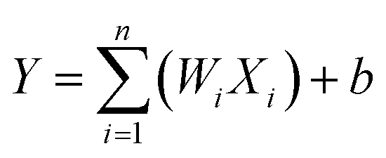
2.2.2 ANN tool. The ANN is an artificial intelligence architecture that draws its organizational principles from the human nervous system. The structure of an ANN consists of a collection of artificial neurons that resemble a simulated brain system. These neurons are meant to mimic simultaneous operations with the goal of achieving certain data objectives. ANN is divided into two types: a single-layered neural networks and multi-layered neural networks. There are typically three levels in a multi-layered neural network: input layers, hidden layers, and output layers. The hidden layer can have a single or more layers, depending on the provided input size and the relationship between the process parameters and response variable. In the beginning, input is provided to the network along with the layer that produces the output, and parameters such as the learning process function, training function, transfer function, the number of neurons, number of layers, and network types are chosen to optimize the given input. Fig. 2(b) depicts the ANN modelling structure implemented in this investigation. Using a specific weight index (W) derived from the output signal, each neuron calculates the weight of each input. The bias (b) and transfer function represent the total weights of the inputs f(WiXi).42 The output can be expressed as eqn (4):| |
 | (4) |
 |
| | Fig. 2 Schematic representation of (a) general steps to perform RSM modelling (b) architecture of ANN model (c) ANFIS architecture. | |
The neural network toolbox of MATLAB R2022b (MathWorks Inc.) was used to perform ANN modeling of Cu–Zn electrodeposition and dealloying process. The input layer consists of four input parameters, while the hidden layer is comprised of ten neurons. This neural network is trained using 70% of the input data, with 15% allocated for both validation and testing purposes.
2.2.3 ANFIS tool. An ANFIS is a key element of fuzzy logic decision-making technology. It establishes essential decision rules by employing “IF… THEN” rules and connectors “OR” or “AND.” A fuzzy inference system (FIS) also provides the relationship between the input and output using a set of fuzzy control rules. The six-layer functions are input, fuzzification, product layer, normalization, defuzzification, and output as illustrated in Fig. 2(c). In order to generate the FIS, three membership functions (MFs) were assigned to each input layer. In this study, the first order Sugeno model with four input variables was applied. Assuming a FIS with two inputs (x, y) and one output (R), Takagi and Sugeno's primary fuzzy rule sets with two IF–THEN rules is as follows:43| | |
Rule 1: IF x is A1 and y is B1, THEN R1 = a1x + b1y + c1
| (5) |
| | |
Rule 2: IF x is A2 and y is B2, THEN R2 = a2x + b2y + c2
| (6) |
where A1, A2 and B1, B2 are fuzzy sets, and R1, R2 are system outputs, and a1, a2, b1, b2 and c1, c2 are adjustable parameters.
2.3 Evaluation criteria for RSM, ANN, and ANFIS model
The performance of the developed machine learning models was estimated by using the equations given below. To calculate the prediction error rates and model effectiveness in regression analysis, the Mean Squared Error (MSE), Mean Absolute Percentage Error (MAPE), and correlation co-efficient (R2) are commonly used.
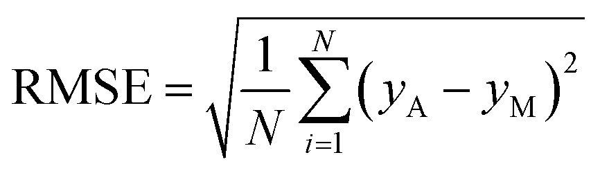
RMSE denotes the difference between the original and expected values determined from the square average difference over the data set, it can be estimated by eqn (7):
| |
 | (7) |
MAPE refers to the average or mean of the predictions' absolute percentage errors, lower the MAPE, the more accurate the prediction. It can be calculated by eqn (8):
| |
 | (8) |
R2 values indicate how closely predicted values match actual values; the greater the R2 value, the more efficient the AI model. It can be evaluated by eqn (9):
| |
 | (9) |
where,
N is the total no. of experimental dataset,
yA,
yp, and
yM represents the actual, predicted, and mean values, respectively.
2.4 Characterization
A field emission scanning electron microscope (FESEM, Thermofisher) was used to examine the structural morphology of pristine and dealloyed substrates at 10 kV. ImageJ software is employed to analyse the grain sizes of electrodeposited and dealloyed substrates using FESEM images. Various images of a substrate have been utilized to calculate the average grain size, and the % change in grain size was calculated by eqn (10):| |
 | (10) |
Energy dispersive X-ray spectroscopy (EDS, Oxford instrumentation) corroborated the element analysis and formation of the composite. EDS analysis was used to evaluate the surface composition of the as-deposited coatings; three readings were obtained at different locations on each sample, and the average was calculated as the final value. The Zn content is determined by the following relationship (11):
| |
 | (11) |
The corrosion characteristics of bare Cu, electrodeposited Cu–Zn, and PC electrodes were examined in 3.5 wt% NaCl. An Autolab (PGSTAT302N) three-electrode cell with Ag/AgCl (3 M KCl), Pt sheet, and Cu electrodes as reference, counter, and working electrodes was used for evaluating electrochemical corrosion. Corrosion inhibiting efficiency of electrodeposited Cu–Zn, PC substrates was calculated based on corrosion current density using eqn (12):
| |
 | (12) |
The substrates were examined by Raman spectroscopy (Bruker Senterra) equipped with a DPSS laser functioning at 2 mW power with a penetration depth of 1 <μm. A contact angle measurement is widely used to characterise a wettability of surface. To determine water wettability, contact angle tests are performed on bare Cu, Cu–Zn, and PC electrodes via a goniometer based on the direct optical approach. An optical goniometer typically comprises of a horizontal stage for mounting the specimen, a syringe for injecting a water droplet, and a built-in camera for examining the water droplet and detecting the contact angle. During the test, the horizontal stage with the mounted specimen is levelled, and the syringe is brought close to the specimen surface using the equipment's knob. The water drop is then impinged on the surface of the sample with the syringe, and the contact angle is determined with the integrated camera. In this investigation, an average droplet volume of 10 ± 1 μL is used. For surface topography measurement, a stylus based formtracer (Mitutoyo, SVC3200H4) instrument has been utilized.
3 Result and discussion
3.1 RSM and ANOVA results
Regression analysis was performed on the set of 29 experimental data at random order, the input parameters, actual and predicted results are presented in Table 2. A quadratic polynomial regression eqn (3) is used to describe the relationship between input parameters and responses. In order to determine the statistical significance of the model equations, an ANOVA test was performed on responses such as: the zinc content, dealloyed weight, and percent change in average grain size. The quadratic model equations offer a good fit for all responses.
The model summary statistics compared linear, quadratic, two-factor interactions (2FI) and cubic models for characterizing the relationship between process parameters and responses. For determining the optimal model for all the responses, correlation coefficient (R2), adjusted R2, predicted R2, and standard deviation were presented in Table 3. Due to an insufficient number of experimental trials, the RSM-BBD is incapable of supporting a complete cubic model.44 A negative value for predicted R2 is not acceptable, so that cubic model is not adequate for prediction of output values. A quadratic model has been selected for further exploration of response values.
Table 3 Statistical summary of models investigated by RSM-BBD for response values
| Model |
Subsequential P-value |
Degree of freedom (Df) |
Standard deviation |
R2 |
Adjusted R2 |
Predicted R2 |
| Response 1: zinc content |
| Linear |
<0.0001 |
4 |
6.33 |
0.7021 |
0.6524 |
0.5453 |
| 2FI |
0.0009 |
10 |
6.64 |
0.7539 |
0.6172 |
0.2381 |
| Quadratic |
0.0004 |
14 |
5.37 |
0.8751 |
0.7502 |
0.2822 |
| Cubic |
0.0071 |
22 |
4.12 |
0.9684 |
0.8527 |
−3.4934 |
![[thin space (1/6-em)]](https://www.rsc.org/images/entities/char_2009.gif) |
| Response 2: dealloyed weight |
| Linear |
<0.0001 |
4 |
0.4824 |
0.7690 |
0.7305 |
0.6675 |
| 2FI |
<0.0001 |
10 |
0.4900 |
0.8212 |
0.7219 |
0.5405 |
| Quadratic |
<0.0001 |
14 |
0.3399 |
0.9331 |
0.8662 |
0.6195 |
| Cubic |
0.0040 |
22 |
0.3216 |
0.9743 |
0.8802 |
−2.5315 |
|
| Response 3: percentage changes in average grain size |
| Linear |
0.0011 |
4 |
6.28 |
0.5201 |
0.4402 |
0.2654 |
| 2FI |
0.0056 |
10 |
5.86 |
0.6862 |
0.5119 |
0.0374 |
| Quadratic |
0.0002 |
14 |
4.01 |
0.8858 |
0.7716 |
0.3483 |
| Cubic |
0.0014 |
22 |
2.42 |
0.9822 |
0.9169 |
−1.3619 |
The ANOVA analysis is performed after the RSM-BBD modelling, and the results of zinc content are displayed in Table 4. The range of zinc content present in electrodeposited Cu–Zn electrode varies from 20% to 68%. The statistical significance of the RSM model was calculated using the F value and p-value of the ANOVA analysis. The F-value is determined by dividing the mean square of regression by the standard error. The model F-value of 7.01 signifies the model is significance, as the probability of such a large F-value occurring by coincidence is only 0.04%. A confidence level of 95% was applied to the p-value to determine the significance of the model and model parameters. Consequently, p-values greater than or equal to 0.05 were deemed statistically insignificant.45 P-Values less than 0.05 indicate the significance of model terms; in this instance, model terms A, B, A2, and B2 are all considered significant. The signal-to-noise ratio was measured with adequate precision, and it is believed that the intended value is greater than 4. The value of 10.665 for adequate precision of Zn content represents an adequate signal, so that the model can be used to navigate the design space. The lack of fit value of 134.03 indicates a significant, with a mere 0.01% probability of such a high value arising from random noise. The quadratic model with standard deviation of 5.37 and R2 of 0.8751 and adjusted R2 of 0.7502 was selected as the most suitable model for depicting the Zn content in the electrodeposited Cu–Zn electrode using the DOE of the specified input variables.
Table 4 ANOVA results for zinc content after electrodeposition
| Source |
Sum of squares |
Degree of freedom |
Mean-square |
F-Value |
P-Value |
|
| Model |
2825.889 |
14 |
201.8492 |
7.007205 |
0.000408 |
Significant |
| A-Copper sulphate conc. |
1875 |
1 |
1875 |
65.09071 |
1.24 × 10⁻⁶ |
|
| B-Zinc sulphate conc. |
352.0833 |
1 |
352.0833 |
12.22259 |
0.003563 |
|
| C-Electrodeposition time |
33.33333 |
1 |
33.33333 |
1.157168 |
0.300243 |
|
| D-Dealloying time |
6.75 |
1 |
6.75 |
0.234327 |
0.635819 |
|
| AB |
30.25 |
1 |
30.25 |
1.05013 |
0.322859 |
|
| AC |
64 |
1 |
64 |
2.221763 |
0.158261 |
|
| AD |
20.25 |
1 |
20.25 |
0.70298 |
0.41587 |
|
| BC |
2.25 |
1 |
2.25 |
0.078109 |
0.783963 |
|
| BD |
30.25 |
1 |
30.25 |
1.05013 |
0.322859 |
|
| CD |
20.25 |
1 |
20.25 |
0.70298 |
0.41587 |
|
| A2 |
239.3878 |
1 |
239.3878 |
8.31036 |
0.012045 |
|
| B2 |
143.2865 |
1 |
143.2865 |
4.974197 |
0.042607 |
|
| C2 |
5.55 |
1 |
5.55 |
0.192669 |
0.667403 |
|
| D2 |
0.583784 |
1 |
0.583784 |
0.020266 |
0.888825 |
|
| Residual |
403.2833 |
14 |
28.80595 |
|
|
|
| Lack of fit |
402.0833 |
10 |
40.20833 |
134.0278 |
0.000132 |
Significant |
| Pure error |
1.2 |
4 |
0.3 |
|
|
|
| Cor total |
3229.172 |
28 |
|
|
|
|
The proposed quadratic model was used to develop a second-order polynomial regression model that related the response (zinc content) to the input parameters (Cu and Zn salt concentration, electrodeposition time, and dealloying time). Eqn (13) represents the mathematical model for zinc content present in electrodeposited Cu–Zn electrode.
| | |
Zn content (%) (R1) = 31.6 – 12.5A + 5.42B − 1.67C + 0.75D − 2.75AB + 4AC + 2.25AD + 0.75BC − 2.75BD + 2.25CD + 6.08 A2 + 4.7B2 − 0.93C2 − 0.3D2
| (13) |
The ANOVA results for the response dealloyed weight is illustrated in Table 5. In this case model P-values <0.0001 indicate the significance of model; in this instance, model terms C, D, CD, C2, and D2 are all considered significant. The model F-value of 13.95 implies that the model is significant, as the probability of such a large F-value occurring by noise is only 0.01%. Similarly, the value of adequate precision, lack of fit, standard deviation, R2 and adjusted R2 are 14.25, 22.7, 0.34, 0.93, and 0.87, respectively suggesting that model is suitable for prediction of dealloyed weight of PC electrode. The quadratic model regression equation for dealloyed weight validated by ANOVA, is expressed by eqn (14) represents the dealloyed weight of zinc after dealloying process.
| | |
Dealloyed weight (mg) (R2) = 3.98 + 0.009A + 0.08B + 0.76C + 0.98D + 0.2AB − 0.025AC + 0.05AD + 0.3BC + 0.15BD + 0.4CD − 0.14 A2 − 0.15B2 − 0.47C2 − 0.53D2
| (14) |
Table 5 ANOVA results for dealloyed weight
| Source |
Sum of squares |
Degree of freedom |
Mean-square |
F-Value |
P-Value |
|
| Model |
22.55525 |
14 |
1.611089 |
13.94739 |
7.17 × 10⁻⁶ |
Significant |
| A-Copper sulphate conc. |
0.000833 |
1 |
0.000833 |
0.007214 |
0.933514 |
|
| B-Zinc sulphate conc. |
0.083333 |
1 |
0.083333 |
0.721426 |
0.409966 |
|
| C-Deposition time |
6.900833 |
1 |
6.900833 |
59.74132 |
2.04 × 10⁻⁶ |
|
| D-Dealloying time |
11.60333 |
1 |
11.60333 |
100.4514 |
9.08 × 10⁻⁸ |
|
| AB |
0.16 |
1 |
0.16 |
1.385139 |
0.258851 |
|
| AC |
0.0025 |
1 |
0.0025 |
0.021643 |
0.885139 |
|
| AD |
0.01 |
1 |
0.01 |
0.086571 |
0.7729 |
|
| BC |
0.36 |
1 |
0.36 |
3.116562 |
0.099292 |
|
| BD |
0.09 |
1 |
0.09 |
0.77914 |
0.392309 |
|
| CD |
0.64 |
1 |
0.64 |
5.540554 |
0.033716 |
|
| A2 |
0.127135 |
1 |
0.127135 |
1.100624 |
0.311903 |
|
| B2 |
0.150851 |
1 |
0.150851 |
1.305938 |
0.272299 |
|
| C2 |
1.402541 |
1 |
1.402541 |
12.14196 |
0.003646 |
|
| D2 |
1.804905 |
1 |
1.804905 |
15.62528 |
0.001444 |
|
| Residual |
1.617167 |
14 |
0.115512 |
|
|
|
| Lack of fit |
1.589167 |
10 |
0.158917 |
22.70238 |
0.004293 |
Significant |
| Pure error |
0.028 |
4 |
0.007 |
|
|
|
| Cor total |
24.17241 |
28 |
|
|
|
|
Table 6 illustrates the ANOVA results for the percentage change in grain size response. In this instance, model P-values of 0.0002 indicate the significance of the model; model elements A, B, D, AD, BC, and A2 are all significant. The model F-value of 7.76 indicates that the model is statistically significant, as the probability of such a large F-value occurring due to noise is only 0.02%. Similarly, the values of adequate precision, lack of fit, standard deviation, R2 and adjusted R2 are 9.89, 31.8, 4.01, 0.89, and 0.78, respectively, indicating that the model is appropriate for predicting percentage changes in grain size prior to and after dealloying of PC electrode. Eqn (15) represents the quadratic model regression equation for percentage change in grain size validated by ANOVA.
| | |
Change in grain size (%) (R3) = 79.2 + 2.75A + 2.75 – 2.25C + 8.1D − 2.5AB + 3AC − 4.75AD − 6BC − 2.25BD + 1.75CD − 6.3A2 − 2.1B2 − 3.1C2 + 2.5D2
| (15) |
Table 6 ANOVA results for percentage change in average grain size
| Source |
Sum of squares |
Degree of freedom |
Mean-square |
F-Value |
P-Value |
|
| Model |
1747.87 |
14 |
124.85 |
7.76 |
0.0002 |
Significant |
| A-Copper sulphate conc. |
90.75 |
1 |
90.75 |
5.64 |
0.0324 |
|
| B-Zinc sulphate conc. |
90.75 |
1 |
90.75 |
5.64 |
0.0324 |
|
| C-Deposition time |
60.75 |
1 |
60.75 |
3.77 |
0.0724 |
|
| D-Dealloying time |
784.08 |
1 |
784.08 |
48.72 |
<0.0001 |
|
| AB |
25.00 |
1 |
25.00 |
1.55 |
0.2331 |
|
| AC |
36.00 |
1 |
36.00 |
2.24 |
0.1569 |
|
| AD |
90.25 |
1 |
90.25 |
5.61 |
0.0328 |
|
| BC |
144.00 |
1 |
144.00 |
8.95 |
0.0097 |
|
| BD |
20.25 |
1 |
20.25 |
1.26 |
0.2808 |
|
| CD |
12.25 |
1 |
12.25 |
0.7612 |
0.3977 |
|
| A2 |
254.73 |
1 |
254.73 |
15.83 |
0.0014 |
|
| B2 |
26.38 |
1 |
26.38 |
1.64 |
0.2212 |
|
| C2 |
59.03 |
1 |
59.03 |
3.67 |
0.0761 |
|
| D2 |
40.00 |
1 |
40.00 |
2.49 |
0.1372 |
|
| Residual |
225.30 |
14 |
16.09 |
|
|
|
| Lack of fit |
222.50 |
10 |
22.25 |
31.79 |
0.0022 |
Significant |
| Pure error |
2.80 |
4 |
0.7000 |
|
|
|
| Cor total |
1973.17 |
28 |
|
|
|
|
Fig. 3 depicts 2D contour and 3D response surface diagrams produced by RSM-BBD statistical modelling and analysis using design expert software for Zn content. Fig. 3(a)–(f) illustrate the interaction effects of Cu and Zn concentration, electrodeposition duration, and dealloying time on response Zn content. The response Zn content is primarily determined by the Zn and Cu concentrations; as the Zn concentration increases and the Cu concentration decreases, the Zn content after electrodeposition increases. Fig. 3(a) shows a red spot on the left corner, indicating that the highest Zn content can be obtained at that concentration.
 |
| | Fig. 3 2D contour and 3D plots for Zn content as a function of Cu, Zn sulphate concentration, electrodeposition time, and dealloying time. | |
Fig. 4 represents 2D contour and 3D response surface diagrams for dealloyed weight. Fig. 4(a)–(f) illustrate the interaction effects of Cu and Zn concentration, electrodeposition duration, with dealloying time on response dealloyed weight. We have observed that the dealloyed weight increases with increasing the dealloying time.
 |
| | Fig. 4 2D contour and 3D plots for dealloyed weight as a function of Cu, Zn sulphate concentration, electrodeposition time, and dealloying time. | |
Fig. 5 exhibits 2D contour and 3D response surface graphs for change in average grain size calculated via ImageJ software. Fig. 5(a)–(f) show the impacts of Cu and Zn content, electrodeposition duration, with dealloying time on response average grain size.
 |
| | Fig. 5 2D contour and 3D plots for change in average grain size as a function of Cu, Zn sulphate concentration, electrodeposition time, and dealloying time. | |
In RSM, a perturbation diagram reveals how changes in input variables (factors) influence the response variable. It guides decision-making in optimization and experimentation, facilitating the identification of critical factors and the modification of processes for enhanced efficiency and effectiveness. Fig. 6 shows the perturbation graph of various responses. From Fig. 6(a) it can be seen that clearly the response Zn content is mainly influenced by the input parameter A, and B. The other two parameters are having very less or no effect over Zn content presence after Cu–Zn electrodeposition. As parameter A decreases and parameter B increases, there is an observed increase in the Zn content. Fig. 6(b) illustrates the correlations between process parameters and the response variable of the dealloyed weight. It has been noted that the most significant parameters influencing the response (dealloyed weight) are C and D. The change in average grain size was calculated before and after the dealloying process, and majorly influenced by parameter D as depicted in Fig. 6(c).
 |
| | Fig. 6 Effect of operating parameters (A: Cu sulphate conc., B: Zn sulphate conc., C: electrodeposition time, D: dealloyed time) on responses (a) Zn content (b) dealloyed weight (c) change in average grain size via perturbation diagram. | |
The graphic representation of the relationship between the actual and anticipated values for RSM-BBD represents the correlation between the actual values of the experiment and the predicted response values obtained through modelling. This graph aids in assessing the precision of the RSM model and the efficacy of the experiment variables. The close relationship between the predicted and actual values of the individual model demonstrates the effectiveness of the model in eliminating imprecise and misleading results.46 Fig. 7(a)–(c) compare the actual value to the predicted value of response zinc content, dealloyed weight, and percentage change in average grain size, respectively.
 |
| | Fig. 7 Scattered plot for actual vs. predicted response of (a) Zn content (b) dealloyed weight (c) change in average grain size, from RSM-BBD model. | |
3.2 ANN model results
Fig. 8 depicts the regression graphs of the ANN model with 10 neurons produced for the estimation of Zn content, dealloyed weight, and percentage change in average grain size. As demonstrated by the graph, predictions of the target values in the training, test, and validation data are derived with a high degree of precision. The coefficients of regression (R2) for the global responses of Zn content, dealloyed weight, and change in grain size are 0.98, 0.96, and 0.96, respectively, indicating that the model is highly accurate.
 |
| | Fig. 8 Regression plots of the ANN model obtained for the prediction of responses (a) Zn content (b) dealloyed weight (c) change in average grain size. | |
3.3 ANFIS model results
Adaptive network-based fuzzy inference system is a network for implementing the optimal input and output correlation decision. The networks are based on a fuzzy inference system, whereas a supervised learning algorithm can govern weighted functions to minimize prediction error, like a neural network. The fundamental ANFIS properties employed in the modelling were listed in Table 7, and the resulting ANFIS sugeno structure was shown in Fig. 9.
Table 7 Properties of ANFIS model employed in the system
| Type of inference system |
Sugeno |
| Number of inputs |
4 |
| Number of outputs |
3 |
| Input membership function type |
Triangular MF |
| FIS |
Sugeno |
| Number of fuzzy rules |
29 |
| Maximum number of epoch |
60 |
| Stopping epoch number |
2 |
| Output MF |
Constant |
| Optimization method |
Hybrid algorithm |
 |
| | Fig. 9 ANFIS sugeno system with four inputs and one output. | |
The ANFIS toolbox with a Takagi–Sugeno network type in MATLAB R2022b software was employed to construct the models. In this study, we have included the most influential types of MFs in our model, including triangular, trapezoid, generalized bell, and Gaussian, with varying numbers. The performance of these MFs was evaluated using the RMSE. The findings of the study revealed that the implementation of the 3-3-3-3 ANFIS architecture resulted in a statistically significant decreases in prediction error when the epoch value was set at 60. The triangular MF produces the lowest prediction error for output responses.
The effect of process parameters on output responses is detected via the established ANFIS model of each response for displaying 3D surface plots and demonstrating two-factor interaction impacts on responses for thorough optimization of the process. Fig. 10 demonstrates the 3D surface plots with interaction of two input factors with responses (Zn content, dealloying time, and change in grain size). From the RSM-BBD model we have observed that the Zn content present in electrodeposited Cu–Zn electrode is mainly dependent on the concentration of copper and zinc sulphate in electrolyte solution. The non-monotonic trend in Fig. 10(a) arises from the combined influence of Zn2+ and Cu2+ ion concentrations on Zn deposition. While higher Zn sulphate concentrations initially promote Zn incorporation, competing effects such as ion activity, diffusion limitations, and interactions with Cu2+ lead to the observed extremum. Others input parameters such as electrodeposition time and dealloying time have very little or no effect on Zn content. Dealloying time and electrodeposited time are the most influential input parameters on the dealloyed weight response from Cu–Zn electrodes, as shown in Fig. 10(b). With increasing dealloying time from 16 to 24 h, the dealloyed weight also got increased from 1.8 mg to 4.9 mg. Similarly, Fig. 10(c) depicts the effect on response change in grain size of electrodeposited Cu–Zn before and after dealloying. With increasing electrodeposition and dealloying times, the grain size of the electrodeposited Cu–Zn also increases.
 |
| | Fig. 10 ANFIS 3D surface plot of responses (a) Zn content with Cu and Zn sulphate concentration (b) dealloyed weight with dealloying time and electrodeposited time (c) change in average grain size with dealloying time and electrodeposition time. | |
3.4 Performance comparison of model
The efficacy of the three models (RSM-BBD, ANN, ANFIS) in modelling the responses Zn content, dealloyed weight, and change in grain size was evaluated by comparing them and presented in Table 8. According to the result, ANFIS and ANN provided a higher level of precision and accuracy for forecasting the responses, whereas RSM-BBD demonstrated the least precision, as indicated by the greatest R2 and the lowest RMSE among all three models. While the majority of studies indicate that ANN and ANFIS are superior to RSM, the same level of consensus does not always apply when determining whether ANFIS is superior to ANN or vice versa, or if one performs better than the other. The ANFIS model has the highest R2 value (0.99) and the lowest MAPE (0.003, 0.002, and 0.001 for Zn content, dealloyed weight, and grain size changes respectively) value among the three models for all the responses.
Table 8 Statistical evaluation of RSM-BBD, ANN and ANFIS models
| Response |
Zn content |
Dealloyed weight |
Change in grain size |
| RSM-BBD |
ANN |
ANFIS |
RSM-BBD |
ANN |
ANFIS |
RSM-BBD |
ANN |
ANFIS |
| RMSE |
9.87 |
10.95 |
10.56 |
0.88 |
0.95 |
0.91 |
7.76 |
8.2 |
8.24 |
| MAPE |
0.08 |
0.032 |
0.003 |
0.056 |
0.057 |
0.002 |
0.031 |
0.015 |
0.001 |
| R2 |
0.88 |
0.96 |
0.99 |
0.93 |
0.92 |
0.99 |
0.89 |
0.91 |
0.99 |
3.5 Surface morphology and EDS analysis
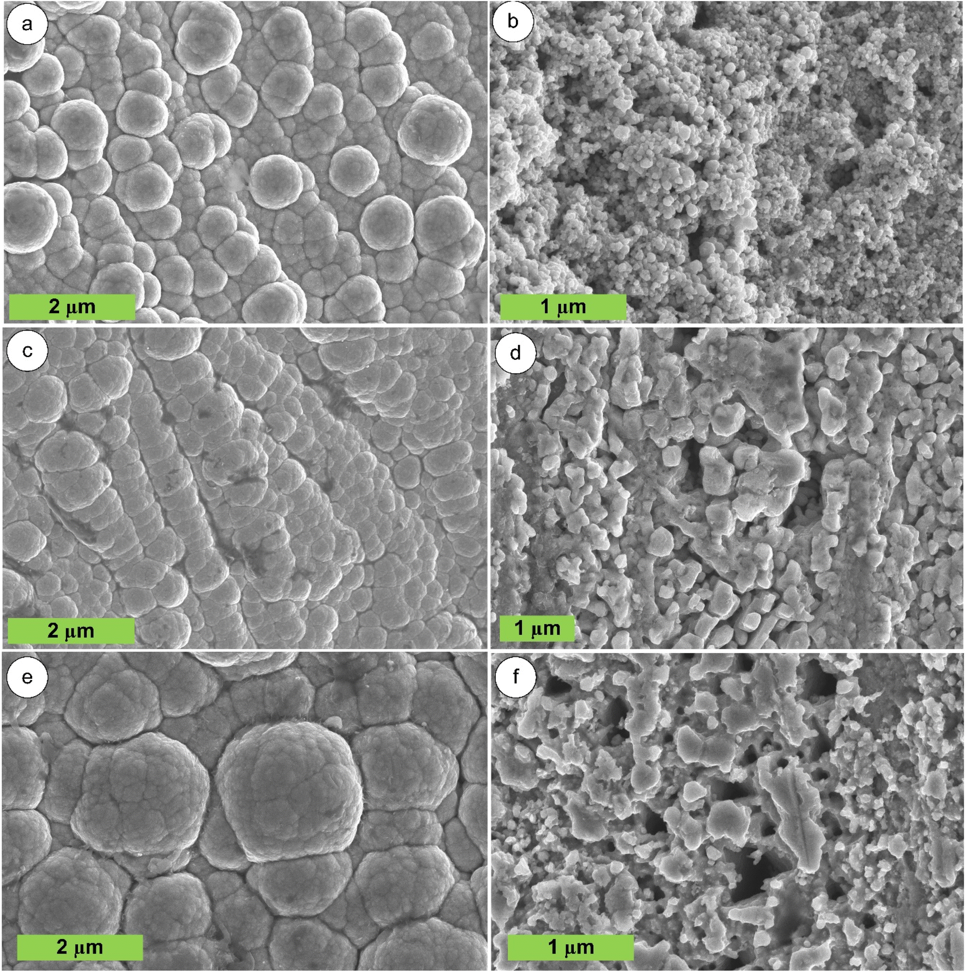
The FESEM micrograph of electrodeposited Cu–Zn over Cu wire is presented in Fig. 11 before and after dealloying. We have shown three sample's FESEM images S-8, S-10, and S-12, details are given in Table 2. Fig. 11(b, d, and f) shows time-resolved FESEM images of treated Cu–Zn alloy electrodes following dealloying times of 16, 20, and 24 hours in 1.3 M NaOH at ambient temperature. We noticed that the granules are less prominent after dealloying compared to the initial Cu–Zn electrode that was not dealloyed (see Fig. 11(a), (c) and (e)). Evidently, as the dealloying time increases, the dynamic evolution of the ligaments into a three-dimensional structure is facilitated by a more porous electrode surface.
 |
| | Fig. 11 FESEM morphology of electrodeposited Cu–Zn alloy before and after dealloying of sample (a and b) S-8, (c and d) S-10, and (e and f) S-12. | |
According to the results from EDS analysis, peaks associated with elements Cu, Zn and O were observed in the EDS spectrum. The Zn content of each substrate are presented in Table 2, we have demonstrated only 3 (S-8, S-10, and S-12) substrates elemental results. The elements Cu (52.33%), Zn (39.01%), and O (10.66%) in matrix (Fig. 12(a)) correspond to Cu–Zn electrodeposited for 30 min with 0.011 M and 0.2 M Cu and Zn sulphate concentration respectively. After dealloying for 16 h. Zn content was reduced from 39.01% to 5.90%, and Cu content was increased from 52.33% to 84.51% as shown in Fig. 12(b). As shown in Fig. 12(c) in S-8 substrate we have observed that the Zn content has been raised up to 64.31% as the concentration of Cu decrease to 0.002 M and Zn concentration increases to 0.2 M. The Zn content has been reduced to 3.06% while the Cu content increases to 90.54% after 20 h of dealloying (Fig. 12(d)). Similarly, the Zn content has been reduced from 36.01% (Fig. 12(d)) to 1.64% (Fig. 12(e)) after 24 h of dealloying.
 |
| | Fig. 12 (a) S-8, (b) S-10, and (c) S-12 shows EDS results of electrodeposited Cu–Zn alloy before and (d)–(f) shows the EDS results after dealloying of sample. | |
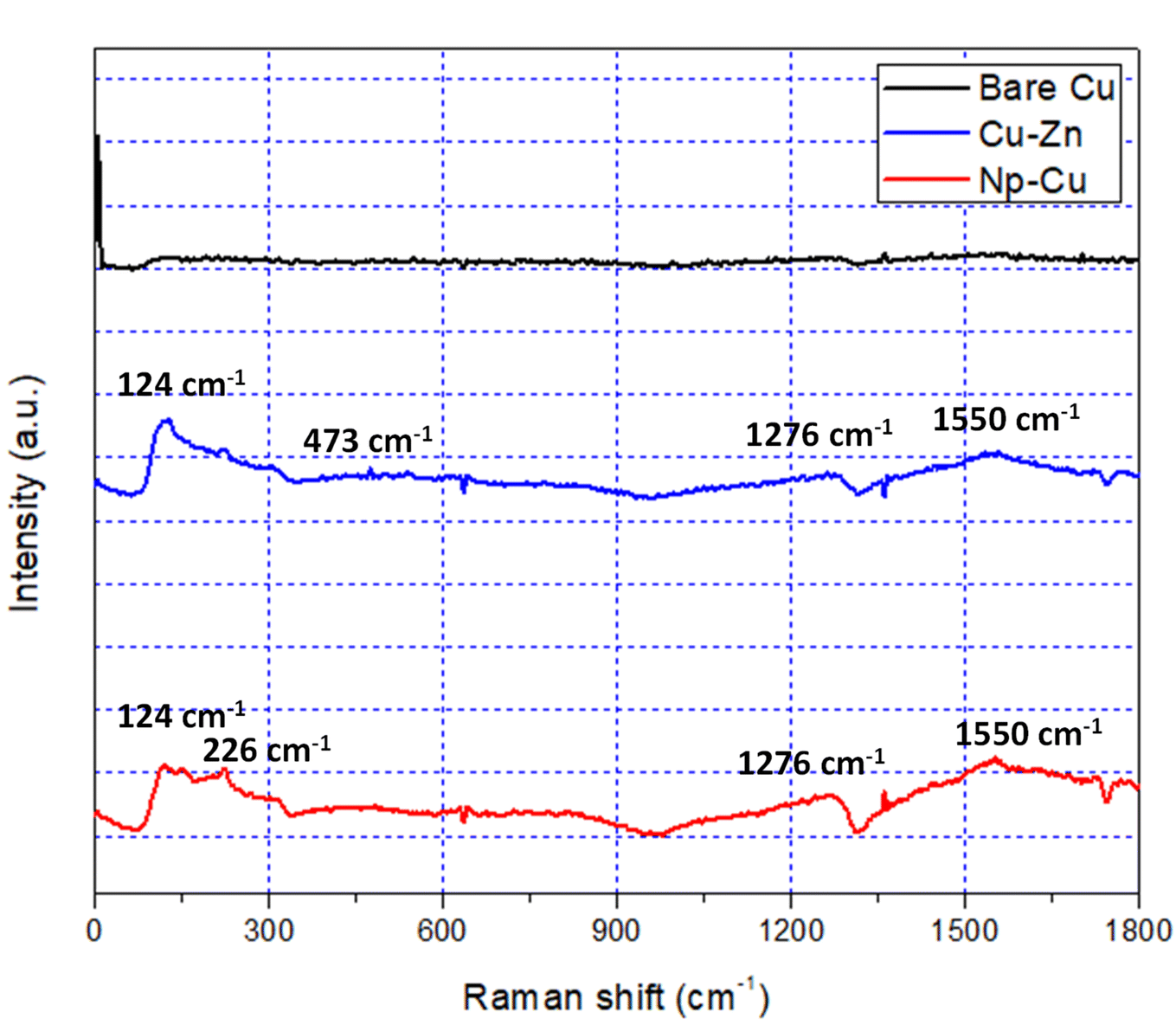
Raman spectroscopy is a beneficial, non-destructive technique that offers precise data on the interaction, composition, and stoichiometry of various oxides. The Raman spectra peak of bare Cu, electrodeposited Cu–Zn, and PC electrode are shown in Fig. 13. Specifically, Raman scattering peaks were observed at 124 cm−1, and 226 cm−1, which can be unequivocally attributed to the presence of Cu and Zn within both the Cu–Zn and Np-Cu electrodes. This observation is consistent with the ability of Raman spectroscopy to discern distinct vibrational modes associated with different chemical species, allowing for precise identification. Furthermore, the presence of two prominent peaks at 473 cm−1 suggests the possible existence of copper oxide (CuO) compounds. This is a noteworthy finding as it indicates the potential presence of oxide phases, which can significantly influence the electrochemical and catalytic properties of the materials.
 |
| | Fig. 13 Raman spectra obtained of bare Cu, electrodeposited Cu–Zn, and PC electrodes. | |
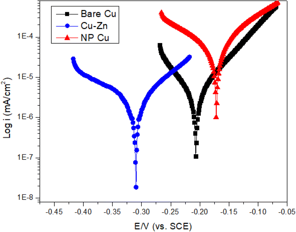
3.6 Electrochemical analysis
The corrosion resistance of untreated Cu, electrodeposited Cu–Zn alloy, and PC electrodes in a 3.5 wt% NaCl solution was assessed by potentiodynamic polarization and depicted in Fig. 14. Corrosion resistance is directly proportional to the corrosion potential (ecorr) and inversely proportional to the corrosion current density (icorr) observed in the potentiodynamic polarization curve.47 The details of corrosion current density (icorr), corrosion potential (Ecorr), anodic Tafel slope (Ta), cathodic Tafel slope (Tc), and inhibition efficiency (np), are listed in Table 9.
 |
| | Fig. 14 Electrochemical characterizations of bare Cu, Cu–Zn electrodeposited, and PC at scan rate 10 mV s−1 in 3.5 wt% NaCl solution. | |
Table 9 Details of potentiodynamic polarization curve of bare Cu, Cu–Zn, and PC electrodes
| Substrate |
icorr (mA cm−2) |
Ecorr (mV) |
Tc (mV dec−1) |
Ta (mV dec−1) |
np (%) |
| Bare Cu |
4.11 |
208 |
−4.11 × 10⁻⁴ |
3.99 × 10⁻⁴ |
— |
| Cu–Zn |
2.84 |
310 |
−1.26 × 10⁻⁴ |
2.15 × 10⁻⁴ |
30.9% |
| Np-Cu |
5.27 |
173 |
−0.0024 |
0.0043 |
−28.2% |
With comparison of a bare Cu electrode, the icorr drops sharply from 4.11 mA cm−2 to 2.84 mA cm−2 and the Ecorr rises from 208 to 310 mV for electrodeposited Cu–Zn alloy. That implies much enhanced corrosion protection by 31%. Furthermore, we have observed that after dealloying the icorr values of Cu–Zn electrodes increase to 5.27 mA cm−2, and Ecorr value decreases to 173 mV, implies that the surface will corrode at faster rate with comparison to bare Cu and Cu–Zn electrode. The results showed an essential correlation between porosity and corrosion rate. Samples with higher porosity had lower Ecorr values, whereas samples with lower porosity had higher Ecorr, which was consistent with our findings.48,49 Analyses of the anodic (Ta) and cathodic (Tc) Tafel slope values revealed that the anodic and cathodic reactions decreased for Cu–Zn alloy but increased for NP-Cu.
3.7 Wettability behavior
The drops were analyzed using the Young–Laplace equation, where a tangent line was formed from the baseline of the drop to the edge, allowing for the determination of the static contact angle. The surface energy, denoted as γs, can be split into two distinct components: the dispersive component, γds, and the polar component, γps.50| | |
γsl = γs + γlcosθ
| (16) |
| | |
γsl = γs + γl − 2[(γds + γdl)½ + (γps + γpl)½]
| (17) |
where γl is the liquid surface tension, θ is the contact angle between the liquid–air interface and the surface, γsl is the interfacial tension between solid and liquid, and γs is the surface free energy of a solid. Fig. 15 illustrates the contact angle measurements of the bare Cu, electrodeposited Cu–Zn, and PC electrodes. Surface roughness is crucial for porous electrodes because it influences the water contact angle (WCA) and its hysteresis on these complex surfaces. These surface characteristics influence not only the apparent wettability of the electrode, but also the trapping of vapour and liquid within the porous structure. WCA measurements for bare Cu electrodes increased from 82° to 111° degrees for Cu–Zn electrodeposited electrodes, indicating a transition towards greater hydrophobicity. In contrast, after dealloying, the porous copper electrodes had a significantly lower WCA of 59°, indicating a strong hydrophilic nature. This change can be attributed to the electrode surface's distinctive porous structure, which is clearly supported by FESEM images (Fig. 11(b), (d) and (f)). Furthermore, as shown in Table 10, shows a clear link between surface roughness and water contact angle. Specifically, as the surface roughness reduces, the WCA increases, indicating that surface topography is important in determining the wetting behavior of these electrodes. Increased surface roughness can lead to higher mountains or deeper valleys on the surface, which may trap less air, thereby inhibiting the spread of liquid water.51 This results in a predominant influence of capillary force and a reduced water contact angle.
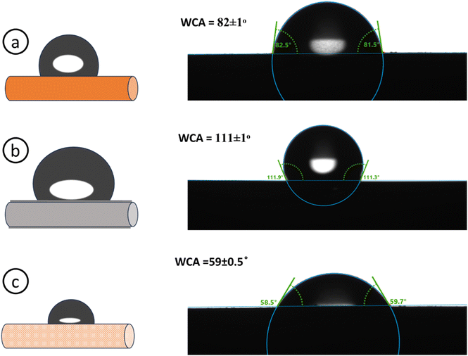 |
| | Fig. 15 Water contact angle of (a) bare Cu, (b) Cu–Zn, (c) NP-Cu electrodes. | |
Table 10 Wetting behavior and surface topography details of Cu, Cu–Zn, PC electrodes
| Substrate |
Contact angle |
Surface roughness |
| Bare Cu electrode |
82 ± 1° |
0.6 μm |
| Cu–Zn electrode |
111 ± 1° |
0.4 μm |
| PC electrode |
59 ± 0.5° |
0.9 μm |
4 Conclusion
In this study, we developed a comprehensive modeling framework for the electrochemical additive manufacturing of Cu–Zn alloy and the subsequent dealloying process to produce porous copper electrode wires. The results indicate that Cu and Zn sulphate concentrations govern the initial Zn content by influencing ion availability, electrodeposition time determines the deposition depth based on other parameters, and dealloying time plays a crucial role in Zn removal and porous structure formation. Using machine learning techniques like ANFIS, ANN, and RSM-BBD, we effectively modeled the complex relationships between process factors and response variables. ANFIS model outperforms both RSM-BBD and ANN models in terms of accuracy, with the highest R2 values (0.99 for all responses) and the lowest MAPE and RMSE values across Zn content, dealloyed weight, and grain size change. While the RSM-BBD model effectively analyzes parameter interactions, ANFIS offers superior predictive performance for the given responses. The FESEM images demonstrate that the grain size has changed significantly after dealloying, and the EDS data show that the Zn concentration has decreased from 64 wt% to 3 wt% after dealloying. The potentiodynamic polarization curves show that Cu–Zn electrodes have greater corrosion resistance properties than bare Cu and PC electrodes, is due to the porous morphology observed after dealloying. The WCA of a Cu–Zn electrode is 111°, indicating hydrophobicity, but it reduces to 59° following dealloying, indicating hydrophilicity. This research underscores the importance of process parameter optimization for achieving desired electrode properties, leading the way for efficient design in applications such as catalysis, sensing, energy storage, and filtration.
Ethical approval
This study did not involve human participants, animals, or sensitive data, and therefore ethical approval was not required.
Data availability
All data supporting the findings of this study are available within the article and the ESI.† These data can be reused in accordance with the journal's data sharing policy.
Author contributions
Prince Kumar Rai: methodology, data curation, formal analysis, validation, investigation, writing – original draft, writing review & editing; Ankur Gupta: conceptualization, formal analysis, validation, investigation, project administration, supervision, writing review & editing.
Conflicts of interest
The authors declare that they have no conflicts of interest or competing interests relevant to this study.
Acknowledgements
The corresponding author wishes to acknowledge the affiliating institute (IIT Jodhpur) for providing the research seed grant (I/SEED/AKG/20190022), which was instrumental in completing the work. The authors would also like to acknowledge Ms Isha Tiwari for assisting in the fabrication work.
References
- J. Zhang and C. M. Li, Nanoporous metals: fabrication strategies and advanced electrochemical applications in catalysis, sensing and energy systems, Chem. Soc. Rev., 2012, 41(21), 7016–7031, 10.1039/C2CS35210A.
- J. Ye, A. C. Baumgaertel, Y. M. Wang, J. Biener and M. M. Biener, Structural optimization of 3D porous electrodes for high-rate performance lithium ion batteries, ACS Nano, 2015, 9(2), 2194–2202, DOI:10.1021/NN505490U/SUPPL_FILE/NN505490U_SI_001.PDF.
- I. V. Okulov, et al., Open porous dealloying-based biomaterials as a novel biomaterial platform, Mater. Sci. Eng., C, 2018, 88, 95–103, DOI:10.1016/J.MSEC.2018.03.008.
- H. Zhao, et al., Compact 3D Copper with Uniform Porous Structure Derived by Electrochemical Dealloying as Dendrite-Free Lithium Metal Anode Current Collector, Adv. Energy Mater., 2018, 8(19), 1800266, DOI:10.1002/AENM.201800266.
- T. T. H. Hoang, S. Ma, J. I. Gold, P. J. A. Kenis and A. A. Gewirth, Nanoporous Copper Films by Additive-Controlled Electrodeposition: CO2 Reduction Catalysis, ACS Catal., 2017, 7(5), 3313–3321, DOI:10.1021/ACSCATAL.6B03613/ASSET/IMAGES/LARGE/CS-2016-036135_0007.JPEG.
- H. J. Biswal, J. J. Kaur, P. R. Vundavilli and A. Gupta, Recent advances in energy field assisted hybrid electrodeposition and electroforming processes, CIRP J. Manuf. Sci. Technol., 2022, 38, 518–546, DOI:10.1016/J.CIRPJ.2022.05.013.
- P. K. Rai, H. J. Biswal and A. Gupta, Development of pulse-electroformed Cu/SiC composite tubes with enhanced mechanical and anti-corrosion properties, Arch. Civ. Mech. Eng., 2024, 24(1), 1–23, DOI:10.1007/S43452-023-00830-4/METRICS.
- A. J. Forty, Corrosion micromorphology of noble metal alloys and depletion gilding, Nature, 1979, 282(5739), 597–598, DOI:10.1038/282597a0.
- J. Snyder, T. Fujita, M. W. Chen and J. Erlebacher, Oxygen reduction in nanoporous metal–ionic liquid composite electrocatalysts, Nat. Mater., 2010, 9(11), 904–907, DOI:10.1038/nmat2878.
- Q. Sang, S. Hao, J. Han and Y. Ding, Dealloyed nanoporous materials for electrochemical energy conversion and storage, EnergyChem, 2022, 4(1), 100069, DOI:10.1016/J.ENCHEM.2022.100069.
- J. R. Hayes, A. M. Hodge, J. Biener, A. V. Hamza and K. Sieradzki, Monolithic nanoporous copper by dealloying Mn-Cu, J. Mater. Res., 2006, 21(10), 2611–2616, DOI:10.1557/JMR.2006.0322/METRICS.
- M. Graf, B. Roschning and J. Weissmüller, Nanoporous Gold by Alloy Corrosion: Method-Structure-Property Relationships, J. Electrochem. Soc., 2017, 164(4), C194–C200, DOI:10.1149/2.1681704JES.
- F. U. Renner, A. Stierle, H. Dosch, D. M. Kolb, T. L. Lee and J. Zegenhagen, In situ x-ray diffraction study of the initial dealloying and passivation of Cu3 Au (111) during anodic dissolution, Phys. Rev. B: Condens. Matter Mater. Phys., 2008, 77(23), 235433, DOI:10.1103/PHYSREVB.77.235433/FIGURES/12/MEDIUM.
- X. Lu, T. J. Balk, R. Spolenak and E. Arzt, Dealloying of Au–Ag thin films with a composition gradient: Influence on morphology of nanoporous Au, Thin Solid Films, 2007, 515(18), 7122–7126, DOI:10.1016/J.TSF.2007.03.023.
- R. K. Dinnappa and S. M. Mayanna, The dezincification of brass and its inhibition in acidic chloride and sulphate solutions, Corros. Sci., 1987, 27(4), 349–361, DOI:10.1016/0010-938X(87)90077-1.
- A. G. Gad-Allah, M. M. Abou-Romia, M. W. Badawy and H. H. Rehan, Passivity of α-brass (Cu:Zn/67:33) and its breakdown in neutral and alkaline solutions containing halide ions, J. Appl. Electrochem., 1991, 21(9), 829–836, DOI:10.1007/BF01402821.
- Z. Zembura and M. Opyrchal, Spontaneous dissolution of Cu 15Zn alloy in aerated or oxygenated 2.0 M H2SO4, Corros. Sci., 1982, 22(12), 1097–1104, DOI:10.1016/0010-938X(82)90096-8.
- M. Li, et al., Controllable nanoporous copper synthesized by dealloying metallic glasses: New insights into the tuning pore structure and applications, Chem. Eng. J., 2022, 427, 130861, DOI:10.1016/J.CEJ.2021.130861.
- Y. Zhan, et al., Facile electrochemical surface-alloying and etching of Au wires to enable high-performance substrates for surface enhanced Raman scattering, Nano Mater. Sci., 2023, 6(3), 305–311, DOI:10.1016/J.NANOMS.2023.05.002.
- Z. Dan, F. Qin, A. Makino, Y. Sugawara, I. Muto and N. Hara, Fabrication of nanoporous copper by dealloying of amorphous Ti–Cu–Ag alloys, J. Alloys Compd., 2014, 586(1), S134–S138, DOI:10.1016/J.JALLCOM.2013.01.087.
- T. Egle, et al., Multiscale Morphology of Nanoporous Copper Made from Intermetallic Phases, ACS Appl. Mater. Interfaces, 2017, 9(30), 25615–25622, DOI:10.1021/ACSAMI.7B05648.
- J. Wang and S. Yang, Nanoporous Copper Fabricated by Dealloying Mn–Cu Precursors with Minor Nickel Element Addition and Heat Treatment Coarsening, Nano, 2018, 13(5), 1850058, DOI:10.1142/S1793292018500583.
- X. Luo, et al., Three-dimensional nanoporous copper with high surface area by dealloying Mg–Cu–Y metallic glasses, Mater. Lett., 2012, 76, 96–99, DOI:10.1016/J.MATLET.2012.02.028.
- H.-Y. Li, et al., Flexible Bimetallic Nanoporous Cu-Ag Synthesized by Electrochemical Dealloying for Battery-Type Electrodes with High Electrochemical Performance, J. Electrochem. Soc., 2018, 165(5), A947–A951, DOI:10.1149/2.0631805JES/XML.
- M. Li, Y. Zhou and H. Geng, Fabrication of nanoporous copper ribbons by dealloying of Al-Cu alloys, J. Porous Mater., 2012, 19(5), 791–796, DOI:10.1007/S10934-011-9532-3/FIGURES/7.
- P. K. Rai and A. Gupta, Review—Electroforming Process for Microsystems Fabrication, J. Electrochem. Soc., 2023, 170(12), 123510, DOI:10.1149/1945-7111/AD0D16.
- P. K. Rai and A. Gupta, Nanofunctionalized pulse-electroformed copper/graphene oxide tubular composite for efficient textile dye degradation under visible light irradiation, Appl. Nanosci., 2022, 12(10), 3045–3060, DOI:10.1007/s13204-022-02612-5.
- P. K. Rai and A. Gupta, Investigation of surface characteristics and effect of electrodeposition parameters on nickel-based composite coating, Mater. Today: Proc., 2021, 44(1), 1079–1085, DOI:10.1016/j.matpr.2020.11.182.
- P. K. Rai, et al., Bi-metallic electrochemical deposition on 3D pyrolytic carbon architectures for potential application in hydrogen evolution reaction, Sci. Technol. Adv. Mater., 2024, 25(1), 2421740, DOI:10.1080/14686996.2024.2421740.
- S. Vivegnis, J. Delhalle, Z. Mekhalif and F. U. Renner, Copper–zinc alloy electrodeposition mediated by triethanolamine as a complexing additive and chemical dealloying, Electrochim. Acta, 2019, 319, 400–409, DOI:10.1016/J.ELECTACTA.2019.07.007.
- S. Vivegnis, M. Krid, J. Delhalle, Z. Mekhalif and F. U. Renner, Use of pyrophosphate and boric acid additives in the copper-zinc alloy electrodeposition and chemical dealloying, J. Electroanal. Chem., 2019, 848, 113310, DOI:10.1016/J.JELECHEM.2019.113310.
- N. T. Tuan, J. Park, J. Lee, J. Gwak and D. Lee, Synthesis of nanoporous Cu films by dealloying of electrochemically deposited Cu–Zn alloy films, Corros. Sci., 2014, 80, 7–11, DOI:10.1016/J.CORSCI.2013.11.043.
- P. K. Du, et al., Preparation of nanoporous copper foil by chemical dealloying from electro-deposited CuZn alloy, Trans. IMF, 2022, 100(3), 145–151, DOI:10.1080/00202967.2021.2022836.
- I. A. Shozib, et al., Modelling and optimization of microhardness of electroless Ni–P–TiO2 composite coating based on machine learning approaches and RSM, J. Mater. Res. Technol., 2021, 12, 1010–1025, DOI:10.1016/J.JMRT.2021.03.063.
- D. E. Millán-Ocampo, J. Porcayo-Calderón, A. Álvarez-Gallegos, J. E. Solís-Pérez, J. A. Hernández-Pérez and S. Silva-Martínez, Electrochemical deposition of copper using a modified electrode with polyaniline film: Experimental analysis and ANN-based prediction, J. Taiwan Inst. Chem. Eng., 2021, 123, 272–283, DOI:10.1016/J.JTICE.2021.05.029.
- H. J. Biswal, P. R. Vundavilli and A. Gupta, Fabrication and Characterization of Nickel Microtubes through Electroforming : Deposition Optimization Using Evolutionary Algorithms, J. Mater. Eng. Perform., 2022, 31, 1140–1154, DOI:10.1007/s11665-021-06223-z.
- P. K. Rai and A. Gupta, Development of a Model for Prediction and Optimization of Hardness of Electrodeposited Cu/SiC Composite Using RSM and ANN-PSO, Manufacturing Equipment and Automation; Manufacturing Processes; Manufacturing Systems; Nano/Micro/Meso Manufacturing; Quality and Reliability, 2023, vol. 2, DOI:10.1115/MSEC2023-101504.
- H. Alhumade, A. G. Olabi, H. Rezk, P. A. Shinde and M. Ali Abdelkareem, Marine predators optimization and ANFIS as an effective tools for maximization of specific capacity of G-NiO electrode for electrochemical energy storage, Ain Shams Eng. J., 2023, 14(10), 102210, DOI:10.1016/J.ASEJ.2023.102210.
- S. A. Ataie and A. Zakeri, RSM optimization of pulse electrodeposition of Zn-Ni-Al2O3 nanocomposites under ultrasound irradiation, Surf. Coat. Technol., 2019, 359, 206–215, DOI:10.1016/J.SURFCOAT.2018.12.063.
- N. T. Tuan, J. Park, J. Lee, J. Gwak and D. Lee, Synthesis of nanoporous Cu films by dealloying of electrochemically deposited Cu–Zn alloy films, Corros. Sci., 2014, 80, 7–11, DOI:10.1016/J.CORSCI.2013.11.043.
- D. J. S. Chong, Y. J. Chan, S. K. Arumugasamy, S. K. Yazdi and J. W. Lim, Optimisation and performance evaluation of response surface methodology (RSM), artificial neural network (ANN) and adaptive neuro-fuzzy inference system (ANFIS) in the prediction of biogas production from palm oil mill effluent (POME), Energy, 2023, 266, 126449, DOI:10.1016/j.energy.2022.126449.
- Y. Xu, Y. Zhu, G. Xiao and C. Ma, Application of artificial neural networks to predict corrosion behavior of Ni–SiC composite coatings deposited by ultrasonic electrodeposition, Ceram. Int., 2014, 40(4), 5425–5430, DOI:10.1016/J.CERAMINT.2013.10.125.
- E. Betiku, Performance evaluation of adaptive neuro-fuzzy inference system, artificial neural network and response surface methodology in modeling biodiesel synthesis from palm kernel oil by transesterification, Biofules, 2018, 12(3), 339–354, DOI:10.1080/17597269.2018.1472980.
- C. E. Onu, J. T. Nwabanne, P. E. Ohale and C. O. Asadu, Comparative analysis of RSM, ANN and ANFIS and the mechanistic modeling in eriochrome black-T dye adsorption using modified clay, S. Afr. J. Chem. Eng., 2021, 36, 24–42, DOI:10.1016/J.SAJCE.2020.12.003.
- S. A. Ataie and A. Zakeri, RSM optimization of pulse electrodeposition of Zn-Ni-Al2O3 nanocomposites under ultrasound irradiation, Surf. Coat. Technol., 2019, 359, 206–215, DOI:10.1016/J.SURFCOAT.2018.12.063.
- P. K. Rai, V. Kant, R. K. Sharma and A. Gupta, Process optimization for textile industry-based wastewater treatment via ultrasonic-assisted electrochemical processing, Eng. Appl. Artif. Intell., 2023, 122, 106162, DOI:10.1016/J.ENGAPPAI.2023.106162.
- P. K. Rai and A. Gupta, Development of durable anticorrosion superhydrophobic electroformed copper tubular structures, J. Manuf. Processes, 2023, 85, 236–245, DOI:10.1016/J.JMAPRO.2022.11.048.
- O. P. Oladijo, B. A. Obadele, A. M. Venter, and L. A. Cornish, Investigation the effect of porosity on corrosion resistance and hardness of wc-co coatings on metal substrates, 2016, Accessed: May 08, 2024. [Online]. Available: https://ujcontent.uj.ac.za/esploro/outputs/journalArticle/Investigation-the-effect-of-porosity-on/9913159007691.
- H. M. Yehia, F. Nouh, O. A. El Kady, W. A. Elaziem and E. M. Elsayed, Studying the microstructure, electrical, and electrochemical behaviour of the Cu-10WC/x GNs for electrochemical machining electrode and energy application, Int. J. Mach. Mach. Mater., 2022, 24(6), 430, DOI:10.1504/IJMMM.2022.128461.
- L. H. Chan, K. Yasuda, J. M. Song and T. Suga, Hydrophilic nanoporous copper surface prepared by modified formic acid vapor treatment, Surf. Interfaces, 2022, 28, 101620, DOI:10.1016/J.SURFIN.2021.101620.
- T. Charinpanitkul, et al., Improved hydrophilicity of zinc oxide-incorporated layer-by-layer polyelectrolyte film fabricated by dip coating method, J. Ind. Eng. Chem., 2012, 18(4), 1441–1445, DOI:10.1016/J.JIEC.2012.02.003.
|
| This journal is © The Royal Society of Chemistry 2025 |
Click here to see how this site uses Cookies. View our privacy policy here. 
 Open Access Article
 This Open Access Article is licensed under a Creative Commons Attribution-Non Commercial 3.0 Unported Licence
 * and
Ankur Gupta
* and
Ankur Gupta