
 Open Access Article
 This Open Access Article is licensed under a Creative Commons Attribution-Non Commercial 3.0 Unported Licence
Development of a face mask attachable wireless piezoresistive nanocomposite sensor for monitoring respiratory health†
D. B.
Niranjan
 ,
Mathew
Peter
,
Jeevan
Medikonda
and
Pramod Kesavan
Namboothiri
*
,
Mathew
Peter
,
Jeevan
Medikonda
and
Pramod Kesavan
Namboothiri
*
Department of Biomedical Engineering, Manipal Institute of Technology, Manipal, Manipal Academy of Higher Education, Manipal, 576104, India. E-mail: pramod.kn@manipal.edu
First published on 26th April 2025
Abstract
A piezoresistance-based stretchable nanocomposite strip that can be attached to a face mask was developed. The wireless acquisition of respiratory activities using this nanocomposite strip was demonstrated. A polyurethane/functionalized-multiwall carbon nanotube (PU/f-MWCNT) nanocomposite was prepared by functionalizing MWCNTs and integrating them with PU. The functionalization of MWCNTs was confirmed using FTIR analysis. A study on the effect of carboxylic functionalization of MWCNTs on the dispersion of MWCNTs in the PU matrix was carried out by measuring resistance at different regions of the nanocomposite. It was observed that carboxylic functionalized CNTs dispersed uniformly in the PU matrix compared with non-functionalized MWCNTs. The electrical percolation threshold for the nanocomposites was achieved at an f-MWCNT concentration of 1.8%. The nanocomposites were further used to fabricate a wearable sensor for integration with a sensor-enabled mask, which could acquire respiratory patterns in real-time. The sensor can identify respiratory patterns, such as the mean time required to complete one respiratory cycle. In normal breathing, the average time to complete one respiratory cycle was 3.44 seconds, with a pause of 0.73 seconds between consecutive cycles. However, for slow breathing patterns, the time required to complete one cycle increased to 7.05 seconds, and the hold time between cycles increased to 2 seconds. Identifying respiratory signal patterns helps identify inhalation and exhalation durations, which thereby helps identify dysfunctional respiration. The developed sensor-based mask is suitable for continuous remote monitoring of respiratory disorders outside the clinical setting. Continuous monitoring of respiratory health can be beneficial for timely intervention or for monitoring respiratory illness and recovery.
1. Introduction
Recent developments in the wearable sensor field have reformed biomedical applications by enabling continuous, non-invasive (or minimally invasive) monitoring of vital bodily functions, such as the heart rate, glucose levels, and physical activity.1–5 Leveraging the innovations in flexible electronics, self-powered technology, wide detection range, compact hardware design, and wireless communication, these devices are engineered for unobtrusive, comfortable wear and allow real-time data that are crucial for both clinical assessments and personal health management.6–10 This continuous monitoring capability supports early disease detection, effective management of chronic conditions, and personalized healthcare strategies. By bridging the gap between conventional diagnostic methods and everyday health tracking, wearable sensors are paving the way for a more patient-focused approach in modern medicine, fundamentally transforming preventive care.11–15 In this regard, conductive polymer nanocomposite-based stretchable strain sensors have gained attention in fabricating wearable gadgets for continuous monitoring. Strain sensors are significant for monitoring a wide range of activities, ranging from motion capture to healthcare applications.16,17 Different types of conductive nanomaterials, including two-dimensional graphene nanoplatelets, one-dimensional carbon nanotubes, zero-dimensional metal nanoparticles, and carbon black, are utilized to enhance polymer matrices such as silicone rubber, polydimethylsiloxane, and polyurethane.18–22 Advances in stretch sensors can enable the fabrication of smart wearable sensors for remote monitoring and real-time analysis of patients for healthcare applications. In pandemic-like situations (such as coronavirus disease, MERS, or influenza), parameters such as respiratory rates are used to assess a patient's clinical status and predict the severity of illness.23–27 More than half of the patients develop respiratory symptoms such as shortness of breath and wheezing, leading to more severe complications, such as pneumonia. In such situations, noncontact-based or remote monitoring helps prevent the spread of disease to healthcare professionals. This method of assessing respiratory patterns minimizes contact between clinicians and patients and, at the same time, helps in monitoring respiratory health in affected patients. Noncontact-based monitoring can aid in identifying early signs of the development of respiratory complications in patients. Several methods are currently used for evaluating respiratory health, as pulmonary function tests range from simple spirometry to assess airflow to whole-body plethysmography, which provides lung volume results.28 However, these methods need a laboratory setting to understand respiratory health and are unsuitable for continuous remote monitoring for long durations. Continuous respiration monitoring is achieved through different methods. In respiratory inductive plethysmography (RIP), two inductive belts are used around the abdomen and ribcage to measure the changes in circumference during respiration and determine the respiratory volume. Kono and Mead developed this volume measurement concept in 1967, which has since been well-established for monitoring patients in a clinical setting.29 Like the RIP method, cameras or depth and acoustic-based sensors can be used to evaluate the patient's respiratory activity. Optoelectronic plethysmography measures respiratory activity by acquiring the movement of the patient's torso from the reflectors placed using several cameras.30 Another method is the measurement of transthoracic impedance by placing different electrodes in configurations such as anterior -apex or apex-posterior positions.31 These methods of continuous respiratory monitoring require specialized equipment or infrastructure, which may not be suitable for remote monitoring. Researchers fabricated devices for monitoring vital signs; however, not many studies reported on a polymer nanocomposite-based breath activity monitoring sensor.32–36In this paper we present a proof-of-concept for the preparation of piezoresistive nanocomposite strips that can be attached to the patient's mask to convert it into a sensor-enabled mask to monitor respiratory health, as shown in Fig. 1. During inhalation and exhalation from the nostrils, direct pressure is placed on nanocomposites, which disrupts the conducting path of MWCNTs in the composites and changes resistance. The change in resistance is recorded and transmitted wirelessly through a mobile or a computer terminal. The data obtained from the sensor-enabled mask is processed, analyzed, and correlated, and finally, the patient's current stage is evaluated.
 | ||
| Fig. 1 Overview of prepared sensor-based mask applications and its versatility. | ||
2. Materials
Pristine multiwall carbon nanotubes (p-MWCNTs) produced using the carbon vapor deposition method (CVD) with a purity of ∼99% were purchased from Adnano Technologies Pvt Ltd, Shimoga, India, and matrix material polyurethane supplied M/s from VCM Polyurethane Pvt. Ltd Mumbai, India. Chemical reagents and nitric acid (HNO3, 65%) were purchased from Sigma-Aldrich. Milli-Q (DI) water was used for all the preparations.3. Result and discussion
3.1. Surface modification of p-MWCNTs
The surface modification of p-MWCNTs was carried out using the acid modification method in which p-MWCNTs were treated with acids and dispersed in solvents. In the acid oxidation method, p-MWCNTs are treated with acids or oxidizing agents, such as HNO3, H2SO4, a mixture of HNO3 and H2SO4, KMnO4, H2O2 and (NH4)2S2O8, etc.37 The several types of surface groups play various functions based on the requirement. Several authors reported using a mixture of HNO3 with H2SO4 in different ratios to treat p-MWCNTS under sonication. As per the literature, treating p-MWCNTs with acids can lead to different surface modifications and defects. The treatment of p-MWCNTs with nitric acid results in the carboxylation of side wall and end caps and can cause more damage to f-MWCNTs at higher concentrations of nitric acid by breaking them into shorter pieces, resulting in a change in the aspect ratio.38 Another study reported the shortening of MWNCTs by ultrasonic treatment in a mixture of H2SO4 and HNO3.39 Osorio et al.40 showed that CNTs did not significantly change with a short exposure to the nitric acid environment. However, long-term exposure increases the carboxyl, C–O, and hydroxyl groups on the side walls of MWCNTs. For the adsorption of COOH and![[double bond, length as m-dash]](https://www.rsc.org/images/entities/char_e001.gif) O, Shanmugharaj et al.41 immersed CNTs in sulfuric acid and potassium dichromate at 80 °C for 30 min. However, treating CNTs for an extended duration resulted in the shortening of CNTs. All these studies show that attaching COOH groups and defect formation on MWCNTs by acid oxidation mainly relies on concentration, reaction time, and temperature.
O, Shanmugharaj et al.41 immersed CNTs in sulfuric acid and potassium dichromate at 80 °C for 30 min. However, treating CNTs for an extended duration resulted in the shortening of CNTs. All these studies show that attaching COOH groups and defect formation on MWCNTs by acid oxidation mainly relies on concentration, reaction time, and temperature.
In this work, the treatment conditions were optimized by keeping the reaction time and the temperature constant and varying the concentration to reduce more damage to p-MWCNTs. The nitric acid concentration was varied from 1 M to 7 M. Fig. 2 depicts the procedure adopted for functionalization. To functionalize p-MWCNTs with COOH groups, 0.1 g of MWCNTs were dispersed in 50 mL of different molar concentrations of HNO3. The mixture was probe-sonicated for 2 hours at 5% of 20 kHz and stirred for 4 hours at ambient conditions. After treatment, functionalized MWCNTs (f-MWCNTs) were washed to remove acid traces using Milli-Q water until the pH became 7. f-MWNCTs were dried at 90 °C overnight in a vacuum oven to remove the water content.
 | ||
| Fig. 2 Functionalization of p-MWCNTs using the acid oxidation method to prepare the nanocomposite. | ||
The surface-modified MWCNTs were further used to prepare nanocomposites using the solution casting method. In this method, polymer and filler materials are dispersed in the solution and cast in a Petri dish or mold to evaporate and form the nanocomposite. Proper filler (f-MWCNTs) dispersion in the polymer matrix is crucial in this process. Therefore, surface modification of MWCNTs with COOH groups is essential to achieve uniform dispersion of fillers in solvents.
3.2. Characterization of MWCNTs and nanocomposites
The morphology of p-MWCNT and f-MWCNTs was analysed using transmission electron microscopy (TEM), as shown in Fig. 3(a). TEM images showed that the outer diameter of p-MWCNTs is 10–30 nm, inner diameter 5–10 nm, and length >1 μm. An IRSpirit Shimadzu instrument was used for the FTIR study. TGA curves of (p-MWCNT and f-MWCNT) are shown in Fig. 3. | ||
| Fig. 3 TEM images of p-MWCNTs (a1 and a2) and f-MWCNTs (a3). (b) FTIR spectra of acid functionalization. (c) TGA curves of MWCNTs. (d1)–(d4) PU and its nanocomposites. (e) Resistance change for different filler loadings of nanocomposites. (f) Uniform electrical properties of the nanocomposite. | ||
TGA analysis was performed under N2 flow, at a heating rate of 10 °C min−1. Fig. 3(b) shows the FTIR spectra of the f-MWCNTs after acid treatment. For this experiment, the concentration of HNO3 varied from 1 M to 7 M. The peak observed for f-MWCNTs at around 1638 cm−1 was attributed to CO bonding, which was not present in p-MWCNT.42 This correlates to the carboxylate anion stretch mode. The peaks around 2400 cm−1 indicate C–O bonding in f-MWCNTs.43 The intensity of this peak increased with HNO3 concentration, which could be attributed to the breakage of p-MWCNTs.44 The peaks observed around 3750 cm−1 are attributed to hydroxyl groups present in f-MWCNTs.45 From Fig. 3(b), it was observed that O–H stretching was maximum for 4 M HNO3 treated f-MWCNTs, indicating a higher degree of carboxylation of MWCNTs. After functionalisation, MWCNTs exhibits lower decomposition temperature due to introduction of –COOH, –OH groups and formation defects as observed in the TGA graphs in Fig. 3(c). Here, for p-MWCNTs and f-MWCNTs, the first degradation step occurs at 563 °C and 521 °C, respectively. This lower decomposition temperature for f-MWCNTs is attributed to surface modifications on MWCNTs.46,47 TEM micrographs show clean, less entanglement and well-defined morphology for f-MWCNTs compared with p-MWCNTs, as shown in Fig. 3(a1)–(a3). For further experiments, 4 M HNO3 treated f-MWCNTs were selected based on FTIR analysis. Nanocomposites of p-MWCNTs and f-MWCNTs are incorporated with polyurethane (PU) by a magnetic stirrer using the solvent mixing technique.12 The prepared nanocomposites of PU/p-MWCNT and PU/f-MWCNT are shown in Fig. 3(d1)–(d3). It was observed that p-MWCNTs unevenly agglomerated in the nanocomposites, as shown in Fig. 3(d2). However, f-MWCNTs showed better dispersion and lower agglomeration than p-MWCNTs nanocomposite in Fig. 3(d3) and (d4). The uniform dispersion of f-MWCNTs in the polymer affects the resistance, as shown in Fig. 3(e). Compared with PU/p-MWCNTs, the PU/f-MWCNTs nanocomposites showed lower resistance due to better dispersion within the PU matrix. The nanocomposites treated with 4 M nitric acid-treated f-MWCNTs nanocomposites showed lower resistance (6 kΩ) compared with those treated with 2 M nitric acid. According to FTIR analysis, f-MWCNTs treated with 4 M HNO3 possibly have higher carboxylic groups on MWCNTs, which increases the hydrophilicity and enhances the compatibility of MWCNTs with the polyurethane (PU) matrix by improving the interaction between the nanotubes and the polymer chains. This results in more uniform dispersion and lower electrical resistance of the nanocomposites.
To understand the effect of functionalization of MWCNTs on the dispersion of MWCNTs in the PU matrix, the distribution of conductivity in the different regions of nanocomposites were studied. For this experiment, nanocomposites with a 5% f-MWCNT concentration were prepared. The two-point probe method was utilized to study the macroscopic electrical resistance of the nanocomposite. Nanocomposites were divided into eight equal parts, and resistance was measured as shown in Fig. 3(f). Experimental results revealed that the resistivity across all regions of nanocomposites was uniform for nanocomposites treated with 4 M HNO3 compared with those with 2 M HNO3. This could be attributed to uniform dispersion and stabilization of 4 M HNO3 treated f-MWCNTs in the matrix. From the dispersion and electrical characterization studies, we chose 4 M HNO3 treated f-MWCNTs for further experiments.
The surface morphology of PU/f-MWCNTs nanocomposite at different dispersion rates is shown in Fig. 4(a)–(a3). Fig. 4(a) shows the surface of pure PU. Fig. 4(a1) shows f-MWCNTs dispersed at below the electrical percolation threshold point. Fig. 4(a2) shows that the agglomeration of f-MWCNTs induces a clump like structure on PU. After optimizing the preparation conditions for the nanocomposite, this agglomeration dispersed uniformly or the agglomeration decreased in diameter to disperse well in the nanocomposite, as shown in Fig. 4(a3). To visualize f-MWCNTs clearly, the top layer was removed and analysed by SEM, as shown in Fig. 4(b1). The f-MWCNTs are covered on the PU membrane, as shown in Fig. 4(b2). This confirms f-MWCNTs bonding in PU. Fig. 4(c) shows the percolation curve of the PU/f-MWCNT nanocomposite. The percolation curve can be divided into three sections. In the first region of the curve, the electrical conductivity was negligible up to 1.8 wt% of f-MWCNTs. A considerable increase in electrical conductivity can be observed in the second region, from 1.8 wt% to 3.1 wt% of f-MWCNTs. This can be attributed to the formation of electrical percolation paths in the nanocomposites. Therefore, 1.8 wt% of f-MWCNTs were considered as the electrical percolation threshold (EPT) of the nanocomposite. The conductivity of the nanocomposite with 3.1 wt% of f-MWCNTs was observed to be 0.01 S cm−1.
 | ||
| Fig. 4 (a)–(a3) SEM micrographs of the surface of nanocomposites at different filler loading conditions. (b)–(b2) SEM micrographs of the surface after removal of the top membrane. (c) Electrical percolation curve of PU/f-MWCNTs nanocomposites. (d) Tensile study of nanocomposites. (e) I–V curves of PU/f-MWCNTs nanocomposites. (f) Illustration of the interface between the filler and the polymer for electrical conduction. | ||
Tensile experiments were conducted to analyse the change in strength of polymer and correlated to the electrical percolation of the nanocomposite, as shown in Fig. 4(d). For this test, ASTM D-638 standard48 was used and nanocomposites were selected at different conducting scales. Various tensile deformation mechanisms were studied for this experiment. The linear region where stress increases linearly with strain is reversible. For pure PU, this linear regime was observed until 0.5 MPa. This regime reduces with inclusion of f-MWCNT in PU. However, stress increases as shown in the inset of Fig. 4(d), attributed to stiffness enhancement due to the influence of f-MWCNTs. In the prepared nanocomposites nucleation for plasticity starts from yield regime. The nanocomposite range increases with higher filler concentration in contrast with pure PU. There is a strain softening regime, with minimal load increasing in strain. For Pure PU, it was 1.03 MPa and the inclusion of f-MWCNTs increases the load transfer in this regime. For viscoelastic materials, after softening over stress, an increase in strain occurs with almost constant load, i.e., steady state flow regime. Here, pure PU exhibits 3.4 MPa of load transfer, while the 0.5 and 1% nanocomposites before percolation are 3.1 and 3.2 MPa, respectively. However, the load transfer increased to 3.9 MPa for the percolation nanocomposite (1.8%). Above percolation 3 and 5% nanocomposites exhibit 4.3 and 7.8 MPa, respectively. This increase in load transfer behaviour in this regime at and above 1.8% nanocomposites is attributed to well-interconnected filler materials in matrix material. However, the decrease in load transfer for the before percolation nanocomposites is due to insufficient fillers dispersed to connect or make network In matrix, which disrupts load transfer. This leads to shortening in steady flow regime. For PU, a prolonged regime is observed due its intrinsic viscoelastic nature.49 This shows that the after inclusion of filler materials at or above the percolation concentration results in the nanocomposites showing improved interfacial load transfer. Maximum load was observed in the strain hardening regime. For pure PU it was, 5.68 MPa, for 0.5% and 1% nanocomposites, it decreased to 4.5 and 4.92 MPa, respectively. For 1.8% nanocomposites, 5.78 MPa was observed. The maximum load increased to 7.18 and 15 MPa in the above percolation nanocomposites, i.e., 3 and 5%, respectively. However, maximum load capacity increased but the elastic regime decreased for the after-percolation nanocomposites. By analysing these mechanisms, the elastic nature of nanocomposites of around 1.8% f-MWCNTs are less affected and the basic matrix characteristics persists while adding a conducing nature to the polymer. This claim is evident by further electrical characterization.
The four-point probe method was used to obtain nanocomposites I–V (current–voltage) characteristics with different f-MWCNT concentrations. Fig. 4(e) shows the I–V curve for the nanocomposite with f-MWCNT concentrations of 0%, 1%, 2%, 3%, and 4% in forward and reverse bias. The IV characteristics of pure PU is almost flat, indicating that PU is an insulating material with very low current flow over the applied voltage range. For 1% f-MWCNTs, the curve shows a slight increase in current with applied voltage compared with pure PU, indicating some level of conductivity but it is still relatively low. For 2% f-MWCNTs, the curve shows a more noticeable increase in current with applied voltage, indicating higher conductivity than the 1% f-MWCNT composite. For 3% f-MWCNTs, the curve demonstrates a further increase in current, showing even higher conductivity. For 4% f-MWCNTs, the curve shows the highest current for a given voltage among all the samples, indicating the highest conductivity. Including f-MWCNTs in the PU matrix significantly enhances the electrical conductivity of the nanocomposites compared with pure PU. This improvement is more evident with increasing weight percentages of f-MWCNTs. At lower concentrations of f-MWCNTs (1% and 2%), the I–V curves are less linear, possibly due to less effective percolation of the conductive network within the PU matrix. For higher concentrations of f-MWCNTs (3% and 4%), the I–V curves show a more linear relationship, indicating ohmic behaviour where the current is proportional to the applied voltage. Above this concertation, the nanocomposite can be considered in the high conductivity region of the percolation curve. Fig. 4(f) shows the interface formation due to the interaction between polymer chains and the surface of the f-MWCNTs. An increase in nanofiller concentration results in the overlap of interfacial layers, a conducting path will be developed, and polymer nanocomposites will show conductivity. Near the electrical percolation threshold, the electrical conductivity of a polymer nanocomposite is expressed as follows:50
| σ = σ0(φf − φp)s | (1) |
| The length of each cube, L = D + l | (2) |
Hence, the volume fraction of CNT agglomerates at the percolation threshold will be,
 | (3) |
 | (4) |
 | (5) |
 | (6) |
 is a constant independent of the strain applied to the nanocomposite.
The distance between the agglomerates (l) increases when the nanocomposite is stretched. Eqn (6) suggests that the electrical conductivity decreases as the distance between the agglomerates above the percolation threshold increases. It can be observed that as the functionalisation increases, agglomeration reduces, and f-MWCNTs are dispersed in the polymer matrix. Therefore, it can be assumed that Dp (the diameter of agglomerates at the percolation threshold) reduces for f-MWCNTs. Because of that, the distance between agglomerates (l) also reduces. This leads to a reduction in the resistance of the PU/f-MWCNT polymer nanocomposites. Functionalization stabilises the MWCNTs and results in more even dispersion of agglomerations (with a smaller diameter) in the polymer, which helps in achieving uniform conductivity in the nanocomposites as shown in the SEM micrographs in Fig. 4(b). Hence, eqn (6) suggests that the ratio of Dp to Df is low, which results in a lower EPT value.
3.3. Development of a face-mask attachable piezoresistive based respiratory sensor
The prepared nanocomposite is attached to the face mask using double-sided tape as shown in Fig. 5(a) and (b). The in-house prepared signal acquisition setup is connected to the electrodes of nanocomposites. The circuit diagrams for acquiring signals are shown in Fig. 5(c). The components of the data acquisition unit (DAU) are shown in Fig. 5(c). The DAU involves the AVR microcontroller (Arduino nano), battery to power the microcontroller, and Bluetooth module for wireless data transmission from the sensor enabled mask (Fig. 5) to a laptop or mobile. The signal acquisition system was designed using an Arduino nano (ATPmega328P) processor with a voltage divider program. Megunolink was used to acquire wireless signals from the nanosensor. Using the current acquisition system, a sampling frequency of 128 points was recorded. After wearing the sensor-enabled mask, data is acquired and transferred wirelessly to the laptop for normal, slow, and fast breathing. The inflow and outflow of air from the nostrils will induce the strain on the nanocomposite, disrupting the conductive path and resulting in a resistance change in the sensor. This change in resistance in the sensor is acquired and processed to analyse breathing patterns. | ||
| Fig. 5 (a) Sensor enabled mask wearing for the test. (b and b1) Sensor and its CAD model and (b2) sensor-integrated mask. (c) Circuit diagram for acquiring signals for fabrication of the DAU. | ||
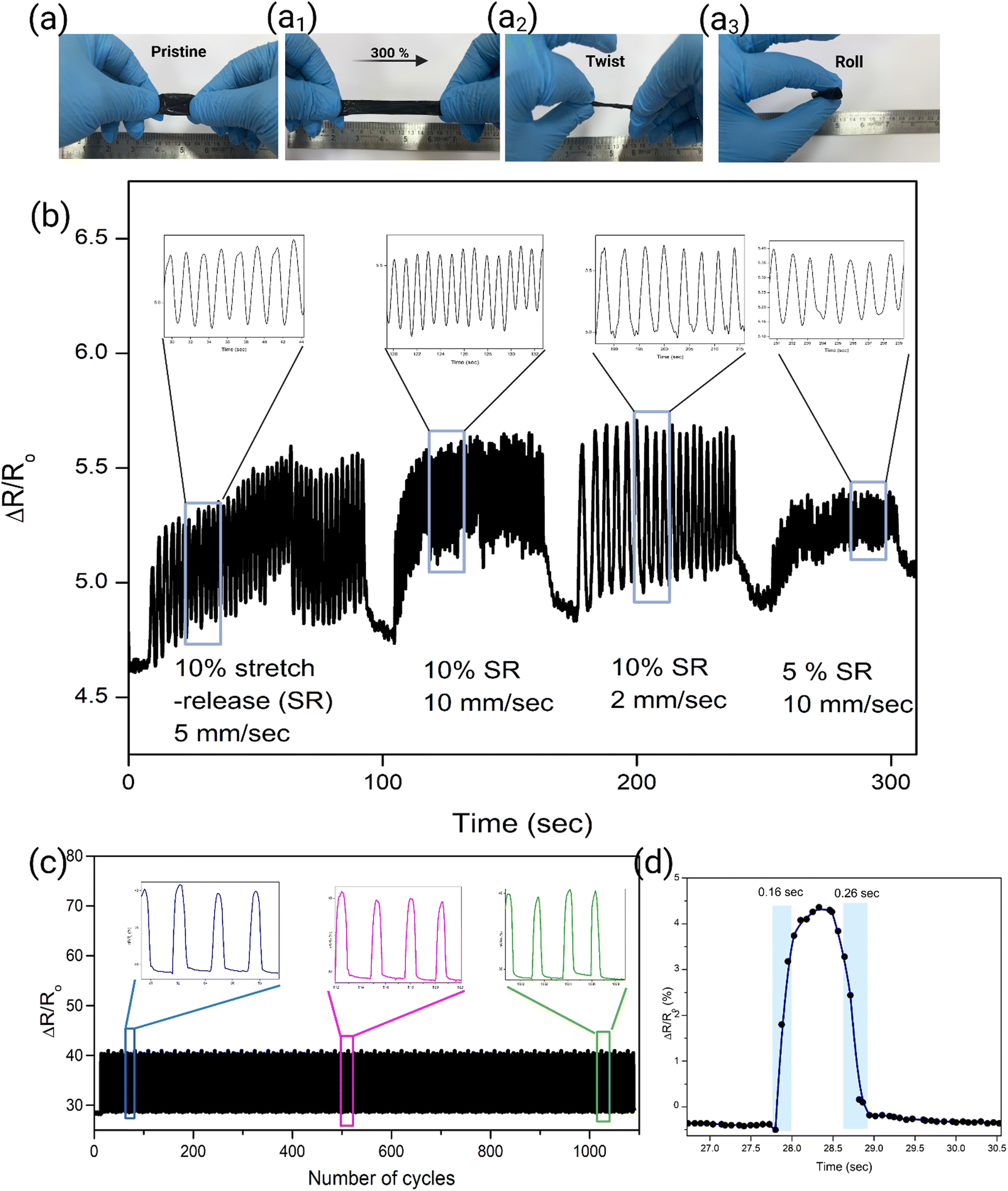 | ||
| Fig. 6 (a)–(a3) Sensors flexible properties. (b) Real-time data of sensor stretch–release performance. (c) Sensitivity of the sensor over prolonged time. (d) Response time of the senor. | ||
3.4. Applications
Fig. 7(a) and (b) demonstrates the respiratory patterns of individuals engaged in normal and slow breathing, acquired using the sensor-enabled mask. The signals are processed using a low-pass filter with a cut-off frequency of 5 Hz. In Fig. 7 and 8, the x-axis represents the time in seconds (s) and the y axis represents the ratio of change in resistance (ΔR/R0). | ||
| Fig. 7 (a) Raw signal of the normal breathing pattern with its (a1) processed signal and (a2) enlarged view with breathing parameters. (b) Raw signal of slow breathing with its (b1) processed signals, and enlarged (b2) view of the same pattern with breathing parameters. | ||
 | ||
| Fig. 8 (a) Raw signal of fast breathing, (a1) processed signal of fast breathing with (a2) the enlarged view. (b) Fast breathing with a hold of 1 s and its (b1) enlarged view. (c) Sneezing pattern with its (c1) enlarged view. (d) Laughing pattern. | ||
For analysis, three respiratory cycles (including exhalation and inhalation) were selected, as shown in Fig. 7(a1) and (b1). The average time required to complete one respiration cycle in the normal breathing pattern signal was 3.44 seconds, as demonstrated in Fig. 7(a2). This pattern also exhibits the presence of a 0.73-second pause between consecutive respiration cycles, as depicted in the detailed view in Fig. 7(a2). Similarly, the time required to complete one respiration cycle increased to 7.05 s on average for slow breathing patterns, as shown in Fig. 7(b), and the hold time between the cycles increased to 2 s. The difference between normal and slow breathing patterns are identifiable from Fig. 7(a) and (b). Identifying respiratory signal patterns facilitates the determination of inhalation and exhalation durations and different breathing patterns.
This sensor-enabled mask can be used for real-time monitoring of respiratory activity in healthcare and sports applications. For instance, in healthcare applications to monitor individuals with acute and chronic intrathoracic blockage during an asthma period by observing prolonged exhalation time. Similarly, inspiration time as shown in Fig. 7(b2) may indicate acute upper airway blockage. The advantage of this sensor enabled mask is that the patients generally show mouth breathing for many respiratory diseases, which can be easily picked up by the developed sensor-enabled mask.
Furthermore, this sensor-enabled mask could obtain data on fast respiration, as demonstrated in Fig. 8(a) and (a1). In fast breathing, data such as one respiration cycle requiring 1.35 seconds can be identified from the sensor enabled mask signals, which was corroborated during the direct measurement experiment. Further, we observed the absence of the hold time between cycles during fast respiration and the presence of hold time in normal and slow respiration was identified in the signals acquired. Additionally, hold of breath during fast respiration was detected and acquired by the sensor-enabled mask, as shown in Fig. 8(b) and (b1). For this action, the directly measured respiration time was the same to 1.60 seconds followed by a hold time of 1 second, which can be clearly observed in the acquired signal in Fig. 8(b1).
As shown in Fig. 8, the developed sensor-enabled mask can help to understand insights into respiratory patterns such as hyperventilation. By continuously monitoring the user's breathing, the sensor-enabled mask can detect variations from normal respiratory rates and patterns and provide am = n early warning of potential respiratory problems.
Further, the sensor-enabled mask demonstrated the acquisition and distinguishing of sneezing and laughing patterns through piezoresistive sensing. Fig. 8(c) and (d) illustrates these patterns with Fig. 8(c1) providing an enlarged view of sneezing patterns. The data reveals a distinct peak within the normal respiratory signals, attributed to the abrupt pressure increase during a sneeze. This sudden pressure disrupts the conducting path, resulting in a noticeable peak in the sensor output.
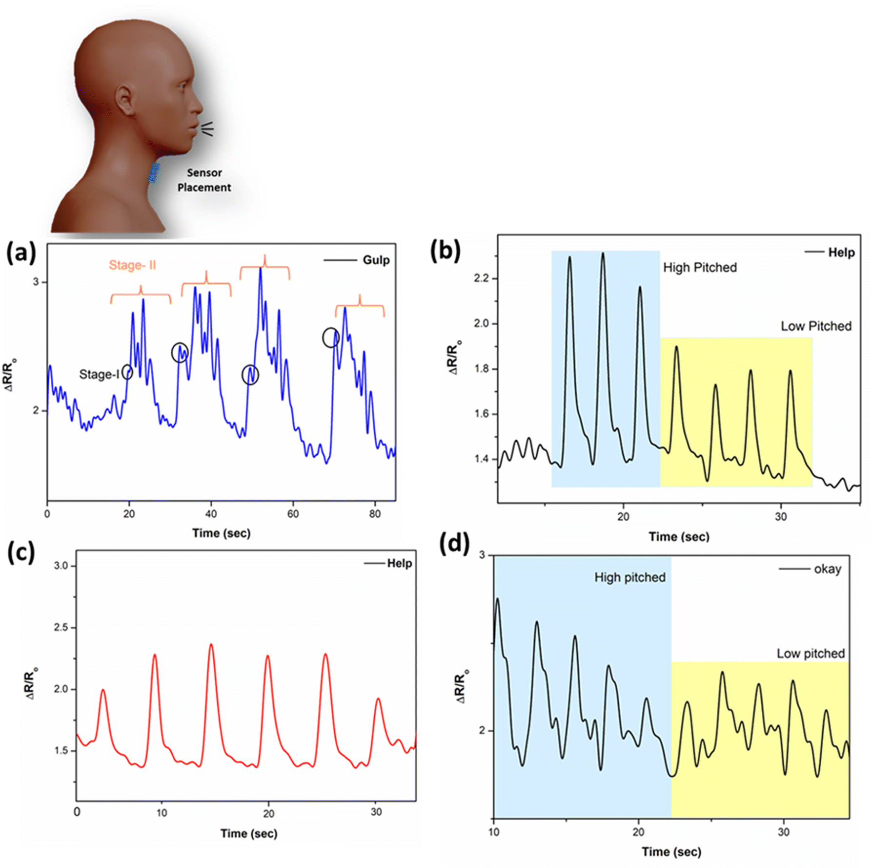 | ||
| Fig. 9 Throat-mounted sensor, acquired (a) gulping action and vocal actions such as (b) and (c) the HELP word at different voice pitches and (d) the OKAY word. | ||
4. Conclusion
The sensor-enabled mask demonstrates capturing and differentiating between normal and slow respiratory patterns, utilizing piezoresistive nanocomposite sensors. Respiratory patterns illustrate the distinct respiratory patterns obtained during normal and slow breathing. Analysis of respiratory cycles shows that the average duration for a normal breathing cycle is 3.44 seconds with a 0.73-second pause between cycles. In contrast, the slow breathing pattern exhibits a cycle duration of 7.05 seconds with a 2-second pause between cycles. These variations in respiratory patterns are clearly identifiable, enabling precise determination of inhalation and exhalation durations. Also, the ability to detect specific respiratory events, such as sneezing, showcases the sensor-enabled mask potential as a sensitive and reliable tool for monitoring respiratory patterns and differentiating between various types of respiratory activities.Continuous monitoring of respiratory health and breathing patterns can be beneficial for timely intervention or as data for diagnoses and understanding the patient recovery process. The paper aims to develop a real-time prototype to monitor patient respiratory health wirelessly. The development of wireless nanosensor strips is attachable and detachable to any mask. Continuous evaluation of breathing is possible. It will also provide information about patients’ respiratory health, recovery, and health monitoring after recovery. This technology could be particularly valuable for health monitoring, offering a non-invasive and accurate method to track and analyze respiratory events in real time.
5. Experimental methods
5.1. Integration of f-MWCNTs to PU matrix
To study the uniform dispersion of f-MWCNTs and its effects on electrical conductivity behaviour, nanocomposites of p-MWCNTs and f-MWCNTs are incorporated with polyurethane (PU) using a magnetic stirrer by the solvent mixing technique and nanocomposites of PU/p-MWCNT and PU/f-MWCNT were prepared from 1, 2, 2.5, 3, 4 and 5%. The water-based PU polymer was added with a 5![[thin space (1/6-em)]](https://www.rsc.org/images/entities/char_2009.gif) :1 ratio with DI water and stirred for 1 h to make solution-1. In another beaker f-MWCNTs are sonicated in a water bath with the aid of water as a solvent for an hour to disperse as solution-2. The f-MWCNT solution was prepared via dropwise addition of solution-2 to solution-1. To enhance the integration of f-MWCNTs with PU matrix, the solution was stirred for 12 h. The addition of f-MWCNT solution to solution 1 is based on the w/w% ratio for the required concentration of nanocomposites. Then, the solution was degassed in a vacuum desiccator for 25 min and poured onto a clean glass Petri dish of 80 cm dia. After that, the solvent was allowed to evaporate in ambient conditions for 24 h to obtain a thin film.
:1 ratio with DI water and stirred for 1 h to make solution-1. In another beaker f-MWCNTs are sonicated in a water bath with the aid of water as a solvent for an hour to disperse as solution-2. The f-MWCNT solution was prepared via dropwise addition of solution-2 to solution-1. To enhance the integration of f-MWCNTs with PU matrix, the solution was stirred for 12 h. The addition of f-MWCNT solution to solution 1 is based on the w/w% ratio for the required concentration of nanocomposites. Then, the solution was degassed in a vacuum desiccator for 25 min and poured onto a clean glass Petri dish of 80 cm dia. After that, the solvent was allowed to evaporate in ambient conditions for 24 h to obtain a thin film.
5.2. Preparation of nanocomposite to piezoresistive sensor
Optimized thin film from the prepared nanocomposite was cut into 70 mm × 10 mm × 0.15 mm dimensions to use as sensor. Copper-based electrodes were attached to the selected nanocomposite using a silver paste to reduce the contact resistance. This piezoresistive sensor was positioned in the middle of the mask. Then, alligator clips are attached to the copper electrodes to connect the DAU.Author contributions
Niranjan D. B. – conceptualization, data curation, formal analysis, funding acquisition, investigation, methodology, project administration, resources, software, supervision, validation, visualization, writing–original draft, and writing – review & editing. Mathew Peter – project administration, supervision, validation, and writing–review & editing. Jeevan Medikonda – project administration, supervision, validation, and writing – review & editing. Pramod Kesavan Namboothiri – formal analysis, funding acquisition, investigation, methodology, project administration, resources, software, supervision, validation, visualization, and writing – review & editing.Data availability
All data supporting the findings of this study are available within the article and its ESI.† Any additional data required to reproduce the results are available from the corresponding author upon reasonable request.Conflicts of interest
There are no conflicts to declare.Acknowledgements
This work was supported by the Indian council of Medical Research, ITR head (5/3/8/40/ITR-F/2022-ITR), Govt. of India; Anusandhan National Research Foundation, Govt. of India (SCP/2022/000264); and Manipal Academy of Higher Education. We acknowledge the research facilities provided by Central Instrumentation facility MAHE, Manipal and Sophisticated Test and Instrumentation Center, Kochi, India. Niranjan acknowledges Mr Shamanth Madapur for valuable inputs on fabricating the circuit diagram for the data acquisition system. Niranjan D. B. is deeply grateful for the invaluable support provided by Vaidehi B. R., whose wisdom continues to inspire us even in her absence. This work has been filed for an Indian patent, under number 202411041475.References
- H. Mai, R. Mutlu, C. Tawk, G. Alici and V. Sencadas., Ultra-stretchable MWCNT–Ecoflex piezoresistive sensors for human motion detection applications, Compos. Sci. Technol., 2019, 173, 118–124 CrossRef CAS.
- Y. Su, Y. Liu, W. Li, X. Xiao, C. Chen, H. Lu and J. Chen, Sensing–transducing coupled piezoelectric textiles for self-powered humidity detection and wearable biomonitoring, Mater. Horiz., 2023, 10(3), 842–851 RSC.
- S. Mishra and B. Saha, Graphene-polymer nanocomposite-based wearable strain sensors for physiological signal Monitoring: Recent progress and challenges, Curr. Opin. Solid State Mater. Sci., 2024, 31, 101174 CrossRef CAS.
- A. Alvarez-Fernandez and J. Maiz, Advancements in polymer nanoconfinement: tailoring material properties for advanced technological applications, RSC Applied Polymers, 2024, 2(6), 1013–1025 RSC.
- X. Wang, H. Li, T. Wang, X. Niu, Y. Wang, S. Xu and H. Liu, Flexible and high-performance piezoresistive strain sensors based on multi-walled carbon nanotubes@ polyurethane foam, RSC Adv., 2022, 12(22), 14190–14196 RSC.
- K. N. Dhakal, R. Lach, W. Grellmann, B. Krause, J. Pionteck and R. Adhikari, Piezoresistivity and strain-sensing behaviour of poly(butylene adipate-co-terephthalate)/multiwalled carbon nanotube nanocomposites, RSC Adv., 2024, 14(48), 35715–35726 RSC.
- Y. Cai, L. Liu, X. Meng, J. Wang, C. Zhang, J. Li and J. A. Duan, A broad range and piezoresistive flexible pressure sensor based on carbon nanotube network dip-coated porous elastomer sponge, RSC Adv., 2022, 12(52), 34117–34125 RSC.
- S. Wang, W. Deng and W. Yang, Superhydrophobic stretchable sensors based on interfacially self-assembled carbon nanotube film for self-sensing drag-reduction shipping, RSC Adv., 2024, 14(36), 26505–26515 RSC.
- Y. Feng, R. Cai, Y. Zhou, Z. Hu, Y. Wang, D. Liu and Q. Meng, A high-performance porous flexible composite film sensor for tension monitoring, RSC Adv., 2022, 12(40), 26285–26296 RSC.
- J. Feng, H. Ao, P. Cao, T. Yang and B. Xing, Flexible tactile sensors with interlocking serrated structures based on stretchable multiwalled carbon nanotube/silver nanowire/silicone rubber composites, RSC Adv., 2024, 14(20), 13934–13943 RSC.
- P. Ananthasubramanian, R. Sahay and N. Raghavan, Investigation of the surface mechanical properties of functionalized single-walled carbon nanotube (SWCNT) reinforced PDMS nanocomposites using nanoindentation analysis, RSC Adv., 2024, 14(22), 15249–15260 RSC.
- D. H. Joo, M. S. Kang, S. J. Park, S. A. Yu and W. T. Park, Fabrication method of flexible strain sensors with CNTs and solvents, Sens. Actuators, A, 2022, 345, 113775 CrossRef CAS.
- S. Bharadwaj, T. K. Gupta, G. S. Chauhan, M. Sehrawat, A. Kumar, S. R. Dhakate and B. P. Singh, Long length MWCNT/TPU composite materials for stretchable and wearable strain sensors, Sens. Actuators, A, 2023, 357, 114364 CrossRef CAS.
- M. Y. Liu, C. Z. Hang, X. Y. Wu, L. Y. Zhu, X. H. Wen, Y. Wang and H. L. Lu, Investigation of stretchable strain sensor based on CNT/AgNW applied in smart wearable devices, Nanotechnology, 2022, 33(25), 255501 CrossRef CAS PubMed.
- T. Hu and B. Sheng, A highly sensitive strain sensor with wide linear sensing range prepared on a hybrid-structured CNT/Ecoflex film via local regulation of strain distribution, ACS Appl. Mater. Interfaces, 2024, 16(16), 21061–21072 CAS.
- L. Liu, X. Zhang, D. Xiang, Y. Wu, D. Sun, J. Shen and Y. Li, Highly stretchable, sensitive and wide linear responsive fabric-based strain sensors with a self-segregated carbon nanotube (CNT)/Polydimethylsiloxane (PDMS) coating, Prog. Nat. Sci.: Mater. Int., 2022, 32(1), 34–42 CrossRef CAS.
- Y. Liu, H. Xiao, D. Pang, S. Sun, Z. Sun and S. Liu, Hybrid structured wearable flexible piezoresistive sensor with high sensitivity and wide detection range, Sens. Actuators, A, 2025, 116520 CrossRef CAS.
- T. Nguyen, M. Chu, R. Tu and M. Khine, The effect of encapsulation on crack-based wrinkled thin film soft strain sensors, Materials, 2021, 14(2), 364 CrossRef CAS PubMed.
- J. Huang, G. Xie, X. Xu, Z. Geng and Y. Su, Degradable multilayer fabric sensor with wide detection range and high linearity, ACS Appl. Mater. Interfaces, 2024, 16(43), 58838–58847 CrossRef CAS PubMed.
- E. D’anna, F. M. Petrini, F. Artoni, I. Popovic, I. Simanić, S. Raspopovic and S. Micera, A somatotopic bidirectional hand prosthesis with transcutaneous electrical nerve stimulation based sensory feedback, Sci. Rep., 2017, 7(1), 10930 CrossRef PubMed.
- S. Choi, S. I. Han, D. Jung, H. J. Hwang, C. Lim, S. Bae and O. K. Park, et al., Highly conductive, stretchable and biocompatible Ag–Au core–sheath nanowire composite for wearable and implantable bioelectronics, Nat. Nanotechnol., 2018, 13(11), 1048–1056 CrossRef CAS PubMed.
- H. Y. Lee, H. Cruz and Y. Son, Effects of incorporation of polyester on the electrical resistivity of polycarbonate/multi-walled carbon nanotube nanocomposite, J. Compos. Mater., 2019, 53(10), 1291–1298 CrossRef CAS.
- Y.-Z. Zhang, K. H. Lee, D. H. Anjum, R. Sougrat, Q. Jiang, H. Kim and H. N. Alshareef, MXenes stretch hydrogel sensor performance to new limits, Sci. Adv., 2018, 4(6), eaat0098 CrossRef PubMed.
- C. Sohrabi, Z. Alsafi, N. O’Neill, M. Khan, A. Kerwan, A. Al-Jabir, C. Iosifidis and R. Agha, Corrigendum to “World health organization declares global emergency: a review of the 2019 novel coronavirus (COVID-19)”[int. J. Surg. 76 (2020) 71–76], Int. J. Surg., 2020, 77, 217 CrossRef PubMed.
- A. Imran, I. Posokhova, H. N. Qureshi, U. Masood, M. Sajid Riaz, K. Ali, C. N. John, M. D. I. Hussain and M. Nabeel, AI4COVID-19: AI enabled preliminary diagnosis for COVID-19 from cough samples via an app, Inform. Med. Unlock, 2020, 20, 100378 CrossRef PubMed.
- E. C. Paraguassu, H. Chen, F. Zhou, Z. Xu and M. Wang., Coronavirus and COVID-19: The latest news and views from the scientific community about the new coronavirus and COVID-19, Braz. J. Implantol. Health Sci., 2020, 2(3), 96–109 CrossRef.
- Y. Wang, Y. Wang, Y. Chen and Q. Qin, Unique epidemiological and clinical features of the emerging 2019 novel coronavirus pneumonia (COVID-19) implicate special control measures, J. Med. Virol., 2020, 92(6), 568–576 CrossRef CAS PubMed.
- C. P. Criée, S. Sorichter, H. J. Smith, P. Kardos, R. Merget, D. Heise and D. Berdel, et al., Body plethysmography–its principles and clinical use, Respir. Med., 2011, 105(7), 959–971 CrossRef PubMed.
- K. Konno and J. Mead, Measurement of the separate volume changes of rib cage and abdomen during breathing, J. Appl. Physiol., 1967, 22(3), 407–422 CrossRef CAS PubMed.
- C. Massaroni, E. Carraro, A. Vianello, S. Miccinilli, M. Morrone, I. K. Levai and E. Schena, et al., Optoelectronic plethysmography in clinical practice and research: a review, Respiration, 2017, 93(5), 339–354 CrossRef PubMed.
- D. M. Caretti, V. Pullen Paul, L. A. Premo and W. D. Kuhlmann, Reliability of respiratory inductive plethysmography for measuring tidal volume during exercise, Am. Ind. Hyg. Assoc. J., 1994, 55(10), 918–923 CrossRef CAS PubMed.
- Y. Khan, A. E. Ostfeld, C. M. Lochner, A. Pierre and A. C. Arias, Monitoring of vital signs with flexible and wearable medical devices, Adv. Mater., 2016, 28(22), 4373–4395 CrossRef CAS PubMed.
- Y. Wang, L. Wang, T. Yang, X. Li, X. Zang, M. Zhu, K. Wang, D. Wu and H. Zhu, Wearable and highly sensitive graphene strain sensors for human motion monitoring, Adv. Funct. Mater., 2014, 24(29), 4666–4670 CrossRef CAS.
- E. Laukhina, R. Pfattner, L. R. Ferreras, S. Galli, M. Mas-Torrent, N. Masciocchi, V. Laukhin, C. Rovira and J. Veciana, Ultrasensitive Piezoresistive All-Organic Flexible Thin Films, Adv. Mater., 2010, 22(9), 977–981 CrossRef CAS PubMed.
- M. Amjadi, K. U. Kyung, I. Park and M. Sitti, Stretchable, skin-mountable, and wearable strain sensors and their potential applications: a review, Adv. Funct. Mater., 2016, 26(11), 1678–1698 CrossRef CAS.
- H. Mai, R. Mutlu, C. Tawk, G. Alici and V. Sencadas, Ultra-stretchable MWCNT-Ecoflex piezoresistive sensors for human motion detection applications, Compos. Sci. Technol., 2019, 173, 118–124 CrossRef CAS.
- L. T. M. Hoa, Characterization of multi-walled carbon nanotubes functionalized by a mixture of HNO3/H2SO4, Diamond Relat. Mater., 2018, 89, 43–51 CrossRef.
- D. S. Ahmed, A. J. Haider and M. R. Mohammad, Comparison of functionalization of multiwalled carbon nanotubes treated by oil olive and nitric acid and their characterization, Energy Procedia, 2013, 36, 1111–1118 CrossRef CAS.
- S. Gómez, N. M. Rendtorff, E. F. Aglietti, Y. Sakka and G. Suárez., Surface modification of multiwall carbon nanotubes by sulfonitric treatment, Appl. Surf. Sci., 2016, 379, 264–269 CrossRef.
- A. G. Osorio, I. C. L. Silveira, V. L. Bueno and C. P. Bergmann, H2SO4/HNO3/HCl—Functionalization and its effect on dispersion of carbon nanotubes in aqueous media, Appl. Surf. Sci., 2008, 255(5), 2485–2489 CrossRef CAS.
- A. M. Shanmugharaj, J. H. Bae, K. Y. Lee, W. H. Noh, S. H. Lee and S. H. Ryu, Physical and chemical characteristics of multiwalled carbon nanotubes functionalized with aminosilane and its influence on the properties of natural rubber composites, Compos. Sci. Technol., 2007, 67(9), 1813–1822 CrossRef CAS.
- K. Y. Hwa and T. S. K. Sharma, Nano assembly of NiFe spheres anchored on f-MWCNT for electrocatalytic reduction and sensing of nitrofurantoin in biological samples, Sci. Rep., 2020, 10(1), 12256 CrossRef CAS PubMed.
- A. P. Sobha and P. S. Sreekala, Electrical, thermal, mechanical and electromagnetic interference shielding properties of PANI/FMWCNT/TPU composites, Prog. Org. Coat., 2017, 113, 168–174 CrossRef CAS.
- L. Stobinski, B. Lesiak, L. Kövér, J. Tóth, S. Biniak, G. Trykowski and J. Judek, Multiwall carbon nanotubes purification and oxidation by nitric acid studied by the FTIR and electron spectroscopy methods, J. Alloys Compd., 2010, 501(1), 77–84 CrossRef CAS.
- N. Sarkar, G. Sahoo and S. K. Swain, Nanocomposites of polyurethane filled with CNTs. Polyurethane, Polymers, Elsevier, 2017, pp. 191–219 Search PubMed.
- T. M. H. Le, N. D. H. Vo, D. M. T. Dang and T. C. D. Doan, Effect of MWCNTs surface functionalization on the characterization of PVA/MWCNTs nanocomposites, Phys. Scr., 2024, 99(7), 075901 CrossRef CAS.
- D. Kumar and P. Jindal, Effect of multi-walled carbon nanotubes on thermal stability of polyurethane nanocomposites, Mater. Res. Express, 2019, 6(10), 105336 CrossRef CAS.
- ASTM, D, ASTM D-638. Standard test method for tensile properties of plastics. ASTM Int., 2014.
- H. Liu, F. Y. Wu, G. J. Zhong and Z. M. Li, Predicting the complex stress-strain curves of polymeric solids by classification-embedded dual neural network, Mater. Des., 2023, 227, 111773 CrossRef CAS.
- S. H. Ji, D. Lee and J. S. Yun, Experimental and theoretical investigations of the rheological and electrical behavior of nanocomposites with universal percolation networks, Composites, Part B, 2021, 225, 109317 CrossRef CAS.
Footnote |
| † Electronic supplementary information (ESI) available: Circuit program for acquiring signals provided and respiratory acquisition demo from sensor enabled mask uploaded as video. See DOI: https://doi.org/10.1039/d4ma01258e |
| This journal is © The Royal Society of Chemistry 2025 |