
 Open Access Article
 This Open Access Article is licensed under a
 Creative Commons Attribution 3.0 Unported Licence
Optimizing the dry processing parameters of thermoplastic vulcanizate electrolytes for improved microstructure and its impact on electrochemical stability†
Mona
Azimi
,
Gabrielle
Foran
 ,
Cédric
Barcha
,
Caroline
St-Antoine
,
Arnaud
Prébé
and
Mickael
Dollé
*
,
Cédric
Barcha
,
Caroline
St-Antoine
,
Arnaud
Prébé
and
Mickael
Dollé
*
Department of Chemistry, Université de Montréal, Campus MIL, 1375 Thérèse-Lavoie-Roux Avenue, Montreal, Quebec H2V 0B3, Canada. E-mail: mickael.dolle@umontreal.ca
First published on 5th May 2025
Abstract
Solid polymer electrolytes have emerged as a promising option for enhancing safety in lithium metal batteries (LMBs), offering advantages such as non-volatility, reduced flammability, straightforward processing, and electrochemical and chemical stability. Nevertheless, they face significant challenges, including limited ionic conductivity at room temperature and insufficient mechanical strength to inhibit dendrite growth. The deliberate engineering of polymer materials with adequate ionic conductivity and mechanical robustness is crucial for ensuring safe and stable batteries. In this study, thermoplastic vulcanizate (TPV) electrolyte systems based on ethylene propylene diene monomer (EPDM) rubber and polycaprolactone (PCL) were prepared using a dry processing method. Unlike solvent-based methods, extruder blending eliminates the use of toxic solvents, reducing environmental hazards and eliminating the need for solvent recovery or disposal, enabling a greener manufacturing process. The impact of processing conditions, such as order of material feeding into the extruder and shear rate, on the morphology (i.e., rubber domain size), mechanical strength, and ionic conductivity of the electrolytes was investigated. The stability of crosslinked polymer electrolytes with different microstructures was studied by cycling in symmetric Li–TPV–Li cells. These experiments connected increased cell resistance with processing conditions, electrolyte morphology and mechanical strength. Longer cycle life was observed for electrolytes with small domain sizes and high mechanical strength. These morphologies were obtained with lower mixing speeds during processing and salt addition following crosslinking of the elastomeric phase.
Introduction
The field of energy storage has witnessed remarkable advancements since the commercialization of lithium-ion batteries (LiBs) in the early 1990's.1 While LiBs remain an established and widely used technology, the quest for higher energy density and more efficient energy storage solutions has led to the development of lithium metal batteries (LMBs). The use of metallic lithium as an electrode material promises to unlock new frontiers in energy storage technology owing to its high theoretical capacity (3860 mA h g−1) and low electrochemical potential (−3.04 V vs. SHE).2 However, the practical use of LMBs presents significant challenges pertaining to safety and cycle life. The high reactivity of Li metal and the uncontrolled formation of lithium dendrites pose significant risks including short circuits, battery failure, and explosions which impede the widespread commercialization of Li metal anodes.3 In systems that employ liquid electrolytes, lithium deposition initially occurs at the base of dendritic protrusions at current densities below the limiting current, resulting in mossy lithium growth. However, as the electrolyte diffusion limitation occurs at higher current densities, lithium ions deposit at the tips of dendritic protrusions, forming dendritic structures that can cause internal short circuits.4 Despite this, dendrite growth and short circuits can happen at much lower current densities. This is possibly due to the onset of diffusion limitations or current concentration at specific points due to microstructural heterogeneity. Solid-state batteries (SSBs) represent a significant advancement, as they address key challenges of traditional liquid organic-electrolyte-based Li-ion batteries, such as flammability and leakage issues, while enabling higher energy density with lithium metal and offering improved safety over flammable liquid electrolytes.5 Several strategies have been introduced to suppress dendrite formation in lithium metal batteries including homogeneous distribution of metal ion flux which is achieved through adding anion-immobilizing moieties or lithiophilic groups to the polymer electrolyte or the use of an artificial solid electrolyte interphase (SEI).6–9 Polymer electrolytes can reduce the possibility of dendrite formation due to their solid structure, which acts as a physical barrier that inhibits dendrite growth and penetration, thus enhancing the safety and longevity of lithium batteries compared to conventional liquid electrolytes. Batteries with polymer electrolytes must be operated at elevated temperatures (i.e., 60–100 °C) owing to the low ionic conductivity of polymer electrolytes at room temperature.10 As the temperature rises, the mechanical strength of polymers can decrease. This decrease can lead to the growth of needle-like dendrites, potentially causing short circuiting. The risk of dendrite formation can be reduced by mechanically blocking dendrite growth via the utilization of polymer composites, polymer crosslinking and polymer structure optimization via block copolymerization.11–13 Cross-linked polymer systems feature a complex network structure that is established through the formation of either covalent bonds or physical bonds between the polymer chain backbones and/or cross-linkers. This complex network affords them elasticity and mechanical robustness.14 In addition to their ability to mechanically inhibit dendrite growth, small-scale interfacial forces arising from the cross-linked polymer structure play a crucial role in reducing dendrite formation.15,16In this study, thermoplastic vulcanizate (TPV) electrolytes were prepared by extrusion. TPV are non-miscible polymer blends that are comprised of a crosslinked elastomeric phase that is dispersed in a continuous thermoplastic phase.17 Most polymer-based electrolytes are prepared by solution casting which involves dissolving the polymers and salt in a suitable solvent, casting the mixture and evaporating off the solvent to yield a film. Solution casting has some disadvantages linked to solvent waste, higher cost and long evaporation times when used on a large scale.18 Extrusion, along with polymer melting and hot pressing have been proposed as alternative solvent-free methods to prepare polymer electrolytes.18 Extrusion, which involves uniformly melting a thermoplastic material before pushing it out through a die with applied pressure, has previously been used to prepare polymer blend electrolytes.19 Unlike non-crosslinked polymer blends, TPV electrolytes must be prepared via extrusion because the crosslinking and the breaking up of the elastomeric phase need to occur simultaneously.17
TPV blends have been extensively used to replace conventional rubbers in industrial applications since the 1970's.20 The first incidence of the use of TPV materials as electrolytes was the PCL–HNBR (hydrogenated nitrile butadiene rubber) electrolytes that were presented by Caradant et al.21 These materials possess improved ionic conductivity compared to blends in which both phases are crosslinked, and improved mechanical strength relative to non-crosslinked PCL–HNBR blends.19,22 The PCL–HNBR TPV electrolytes possessed exceptional electrochemical stability and mechanical strength. The mechanical strength of the crosslinked TPV electrolyte was nearly twice as high as that of the non-crosslinked polymer blend electrolyte.21 Boudeville et al. have previously prepared electrodes comprised of polypropylene, PCL, LiFePO4 and carbon black by solvent-free extrusion.23 The materials, like the above-mentioned electrolytes, were both more durable and more flexible than comparable electrodes that were made from a single polymer.23 A disadvantage of the TPV electrolytes is that they tended to be less conductive than non-crosslinked polymer blend electrolytes which was remedied by Caradant et al. through the addition of small amounts of liquid plasticizer.21 The presence of a crosslinked elastomeric phase meant that the TPV electrolytes maintained sufficient resistance to oxidation to allow for cycling with LiFePO4 and Ni0.33Mn0.33Co0.33O2 electrodes.21
Ethylene propylene diene monomer (EPDM), which undergoes dynamic vulcanization during the blending process, was mixed with polycaprolactone (PCL) to prepare the TPV electrolytes presented here. During dynamic vulcanization, the rubber phase undergoes chemical crosslinking reactions while simultaneously being subjected to intense mechanical shear forces. The partially crosslinked rubber phase imparts elasticity and resilience to the final product, while the thermoplastic phase provides processability and, in the case of electrolytes, ionic conductivity.17 Herein, EPDM is chosen as the elastomeric phase due to its stable polyolefin structure, which provides greater stability when interacting with lithium compared to the reactive acrylonitrile groups in HNBR.24 Previous work has shown that exposure to nitriles results in the formation of Li3N.24 Furthermore, electrochemical studies of a poly(ethylene oxide) (PEO)–HNBR electrolyte in a Li–Li cell reveal that interactions between the lithium metal surface and the HNBR in the polymer blend cause the interfacial resistance to change over time, reducing cell stability.24
PEO is a better ionic conductor than PCL due to improved ion dissociating ability and higher ion affinity.25,26 PCL was chosen over PEO as the thermal plastic phase in these electrolytes as it has improved affinity with EPDM which allows for easier processing during dynamic crosslinking and the formation of smaller rubber domains. Obtaining desirable morphology in a TPV requires good compatibility between the thermoplastic and elastomeric phases. This is typically enabled by blending phases with similar properties.27 One such property is solubility. Solubility parameter ‘distance’ (Ra) can be calculated based on eqn (1) where δd, δp and δh are the Hansen solubility parameters for the dispersion, polar and hydrogen bonding interactions respectively.28
| Ra2 = 4(δd2 − δd1)2 + (δp2 − δp1)2 + (δh2 − δh1)2 | (1) |
The Hansen solubility parameters for EPDM, PEO and PCL, along with the respective Ra values for PEO and PCL are given in Table 1. It can be observed that the solubility of PCL is closer to that of EDPM than the solubility of PEO is. This makes PCL a better choice for the thermoplastic phase as higher compatibility with EPDM will result in improved dispersion of the thermoplastic phase in the resultant TPV electrolyte.
Processing parameters, in addition to the characteristics of the component polymers, impact the properties of the resultant TPV material. This work therefore explores the impact of processing parameters, such as the order of material addition and screw speed, on the morphology, mechanical properties and cycling stability in a symmetric Li–Li cell configuration of the PCL–EPDM TPV electrolytes. These issues were not addressed in Caradant et al.'s preliminary work on TPV electrolytes and yet are anticipated to have a significant impact on electrolyte performance and stability.
Results and discussion
Peroxide molecules are added during the dynamic vulcanization of EPDM. The peroxides undergo homolytic cleavage to generate free radicals which then react with the unsaturated sites present along the EPDM polymer chain. These are predominantly the double bonds in the diene monomer units. This process occurs at elevated temperatures. This initiation step results in the formation of macroradicals within the elastomeric phase. Subsequently, during the propagation stage, these macroradicals propagate through the EPDM phase by abstracting hydrogen atoms from neighboring chains resulting in the formation of longer chains.30 The crosslinking mechanism of EPDM with a peroxide crosslinking agent along with two possible crosslinking network configurations of EPDM (through combination and addition) are illustrated in Fig. 1(a).31 PCL, which is used as the thermoplastic phase, contains polar ester functional groups within the backbone structure (Fig. 1(b)) and has a donor number of 17.32 This feature enables PCL to effectively dissociate salts (e.g., LiTFSI) through electrostatic interactions.32 In contrast, the non-polar EPDM cannot dissociate salts. Fluorine mapping of the prepared electrolytes by energy dispersive X-ray (EDX) analysis (Fig. S1, ESI†), confirms that LiTFSI interacts exclusively with the PCL phase. Fig. 1(c) presents an optical image of the TPV electrolyte film, highlighting its homogeneity, flexibility, and freestanding nature, alongside a schematic representation of its structure. | ||
| Fig. 1 Crosslinking of EPDM with peroxide crosslinking agent (a), molecular structure of PCL and LiTFSI (b), and optical image of TPV film and scheme of the structure of a TPV electrolyte (c). | ||
Fig. 2 shows SEM images of TPV electrolytes that were prepared using different processing conditions. Phase inversion and the attainment of a uniformly distributed rubber phase within the plastic matrix are two important factors in the formation of the microstructure of the TPV electrolyte. The thermoplastic phase is typically dispersed within the continuous rubber phase before the rubber phase undergoes crosslinking. The thermoplastic phase then melts, causing the two phases to merge and form a co-continuous structure. Phase inversion occurs as the crosslinking agent initiates crosslinking, leading to an increase in the viscosity of the rubber phase. This is the result of an increase in crosslink density. This phase inversion typically advances through a co-continuous structure. Following this, the continuous rubber phase is extended into unstable fibrillar structures. The rubber phase then eventually breaks down into micro-particles which are dispersed within the plastic matrix as the crosslink density continues to rise during vulcanization. This phenomenon is driven by the rapid increase of viscosity and shear stress acting on the rubber phase, thereby facilitating the process of phase inversion.33 The SEM images of the prepared TPV electrolytes show two distinct phases, demonstrating the immiscibility of the crosslinked rubber phase and the thermoplastic phase.
 | ||
| Fig. 2 SEM images of TPV-A (a), TPV-B (b), TPV-C (c), TPV-D (d), and histogram of rubber domain size for various TPV electrolytes (e). | ||
Fig. 2(a) depicts an EPDM/PCL TPV electrolyte where LiTFSI salt was added prior to the crosslinking of the EPDM rubber. The screw speed in the extruder was 250 rpm during mixing (TPV-A). The average domain size of the rubber phase in this sample markedly surpasses those of TPV-B and C but remains smaller than that of TPV-D. LiTFSI could potentially reduce the viscosity of the PCL phase by increasing its plasticity.34,35 This change in viscosity prior to EPDM crosslinking significantly influences the final morphology of the TPV electrolyte. The plasticization of the thermoplastic phase through the incorporation of salt increases the difference in viscosity between the two phases, which facilitates the coalescence of the rubber domains during processing, thus explaining the large domain sizes observed in TPV-D (Fig. 2(d)). As the blend flows more easily, smaller rubber particles have a higher tendency to coalesce and merge into larger domains. Lower viscosity may also result in reduced shear forces acting on the rubber phase during processing. Shear forces can contribute to the breakup of rubber domains. With lower viscosity, there is less resistance to these forces, allowing for the conservation of larger rubber domains.36Fig. 2(b) represents TPV-B where the salt is added after the crosslinking of the EPDM at a screw speed of 250 rpm. In this case, the rubber domains are significantly smaller than those found in TPV-A and are more uniformly dispersed in the PCL matrix. Fig. 2(c) shows the SEM image of (TPV-C) which was prepared using a lower screw speed (150 rpm). LiTFSI salt was added after crosslinking the EPDM rubber. The decrease in screw speed results in larger domain sizes compared to TPV-B. This was likely caused by reduced shear forces acting on the rubber phase. Decreased agitation means that the rubber particles are less likely to break down into smaller domains. Consequently, they can coalesce more easily, forming larger domains within the thermoplastic matrix. A histogram showing the distribution of rubber domain size in the four different TPV electrolytes is presented in Fig. 2(e). TPV-B contains the greatest proportion of small rubber domains with sizes ranging from 0.5–1 μm2. TPV-A and D contain the largest rubber domains, with the smallest starting in the range of 8.5–9 μm2.
The mechanical strength of the samples was evaluated through tensile measurements and rheological analysis. The strain–stress curves presented in Fig. 3(a) show that the tensile strength of TPV-C is 0.85 MPa which is two times higher than that of TPV-A. The elongation at break of TPV-A and TPV-B are 650% and 480%, respectively which are 45% and 4% higher than that of TPV-C. The inclusion of dispersed rubber domains within a polymer matrix typically enhances tensile strength up to a certain threshold. This enhancement arises from the ability of rubber domains to dissipate energy and resist crack propagation, thereby improving the toughness of the material.37 The size of the rubber domains in the TPV electrolytes significantly affects their mechanical strength. Smaller rubber domains enhance the material's mechanical properties by suppressing interlamellar void formation, preventing void coalescence, promoting homogeneous stress distribution, and reducing stress concentration points.38 However, when the size of the dispersed rubber domains increases, they can become stress concentrators, resulting in premature failure and a reduction in tensile strength. This is attributed to the localized stress concentrations around larger rubber particles, which facilitate crack initiation and propagation.38,39
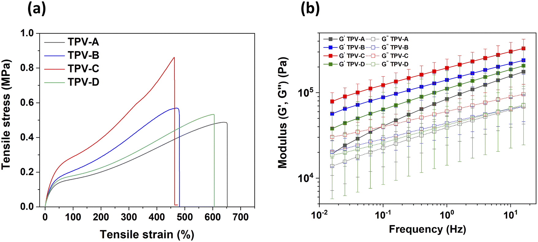 | ||
| Fig. 3 Stress–strain curves of the TPV electrolytes (a), storage-loss modulus curves as a function of frequency at 130 °C (b). | ||
It seems counterintuitive that TPV-B, which has the smallest rubber domains, has lower tensile strength than TPV-C. It is believed that elevated shear rates caused by the use of a faster screw speed during processing may subject the polymer chains to increased mechanical stress, leading to chain scission or other forms of degradation in the PCL phase.40 This hypothesis was tested by performing nuclear magnetic resonance (NMR) spectroscopy on the TPV electrolytes (Fig. S2, ESI†). The extent of polymer chain scission in the PCL fraction of the TPV electrolytes was gauged by comparing the peak ratios in the 1H NMR spectra (values are given in Table S1, ESI†). Chain scission is expected to decrease the fraction of ester groups relative to the alkyl groups. Based on this criterion, TPV-A which was mixed at 250 rpm with LiTFSI added prior to crosslinking experienced the most chain scission during preparation. Lower mixing speed and LiTFSI addition after crosslinking (TPV-C) resulted in the least chain scission. To gain deeper insight into the influence of screw speed and the sequence of salt addition on PCL chain scission, a sample (TPV-D) was prepared at a screw speed of 150 rpm, with salt introduction prior to the crosslinking step. NMR analysis indicated that the extent of chain scission across the TPV samples follows the order: TPV-A > TPV-D > TPV-B > TPV-C. The observation of slightly more chain scission in TPV-D than in TPV-B suggests that adding LiTFSI prior to crosslinking has a greater influence on PCL chain scission during TPV electrolyte preparation than screw speed does. These results align with the mechanical strengths of the various TPV electrolytes. TPV-D exhibited a mechanical strength of 0.5 MPa and an elongation of 600%. This sample was found to have lower mechanical strength than TPV-B Fig. 3(a).
The mechanical strength of a non-crosslinked PCL–EPDM sample was evaluated to emphasize the impact of crosslinking on the strength and durability of the material. Fig. S3(a) (ESI†) shows that the tensile strength of the non-crosslinked PCL-EPDM sample, 0.13 MPa, is substantially lower than that of the crosslinked samples. This considerable difference can be attributed to the impact of crosslinking on the structural integrity of the sample. In the non-crosslinked state, the polymer chains can move more freely, which results in weaker intermolecular forces and lower mechanical strength.
The thermal stability of the TPV electrolytes was studied by thermogravimetric analysis (TGA). Observations indicate that the thermal stability of all the TPV electrolytes is consistent, with no mass loss observed until 300 °C. Mass loss in the TPV electrolytes starts at temperatures above 300 °C and proceeds in three distinct steps. The first mass loss, commencing at approximately 320 °C, can be attributed to PCL. Subsequently, the second mass loss is associated with EPDM, and the final stage of mass loss corresponds to LiTFSI (Fig. S4, ESI†).41 Electrolyte morphology did not have a significant impact on thermal stability.
The rheological properties of the TPV electrolytes were evaluated in the melt phase at 130 °C. The variation of G′ and G′′ as a function of angular frequency is depicted in Fig. 3(b). The graphs show that the storage modulus of the TPV electrolytes is consistently higher than the loss modulus across the entire frequency range (0.1–100 rad s−1), indicating that these electrolytes exhibit predominantly elastic behavior. The values of G′ and G′′ increase gradually as a function of frequency for all TPVs. This is because at low frequencies, sample deformation occurs over a longer time period, resulting in a lower G′. This behavior is due to the extended relaxation time available to the polymer chains. During this time, the polymer chains have the opportunity to undergo significant rearrangement and relaxation, allowing them to return to an equilibrium state. Consequently, the material exhibits reduced stiffness and elasticity because the polymer chains accommodate and adapt to the imposed deformation more easily. This increased molecular mobility at lower frequencies leads to a lower G′, reflecting the greater ability of the material to relax and deform under slow, sustained stress compared to fast deformation at higher frequencies.42 The storage modulus of TPV-C is nearly four times greater than that of TPV-A. This significant difference, when combined with tensile test results, highlights the superior mechanical stability of TPV-C. The enhanced performance of TPV-C can be attributed to the more homogeneous distribution and smaller size of the rubber domains compared to TPV-A and TPV-D and the retention of the structural integrity of PCL compared to TPV-B. This contributes to its robustness and stability under mechanical deformation. As mentioned earlier, the degradation of PCL at higher extruder rotation speeds compromises the mechanical stability of TPV-B, despite its smaller rubber domain sizes. This degradation weakens the thermoplastic phase, preventing it from achieving the superior mechanical stability seen in TPV-C. TPV-B exhibited a higher storage modulus than TPV-A and TPV-D, though it remains lower than that of TPV-C. TPV-A, with the highest screw speed and the addition of salt before crosslinking, exhibits the lowest mechanical strength among the TPV electrolytes. The combination of these two detrimental factors leads to the lowest storage modulus in TPV-A. In contrast, reducing the screw speed, as in TPV-D, results in a slightly higher storage modulus, though it remains lower than that of TPV-C and B. These findings correlate with the extent of PCL degradation as determined by NMR spectroscopy showing that both phases contribute to the observed mechanical strength.
The rheological properties of a non-crosslinked PCL–EPDM blend were also evaluated (Fig. S3(b), ESI†). This sample exhibited significantly different behavior than its crosslinked counterpart. Notably, in the non-crosslinked sample, a crossover between the storage modulus (G′) and loss modulus (G′′) was observed. This indicates that at low frequencies, the material behaves as viscous-dominant, with the loss modulus exceeding the storage modulus.43 As the frequency increases, a transition occurs, shifting the material's behavior from viscous-dominant to elastic-dominant, where the storage modulus surpasses the loss modulus.43 In contrast, the crosslinked samples do not exhibit a crossover point because crosslinking creates a network of covalent bonds between polymer chains. This bonding prevents chain mobility and viscous behavior, even at low frequencies, resulting in the material behaving predominantly as an elastic solid across the entire frequency range.43
Subsequent electrochemical tests were conducted on TPV-A, TPV-B, TPV-C and TPV-D to assess the impact of mechanical strength on the electrochemical properties of the material. Ionic conductivity measurements were performed in a coin cell configuration at temperatures ranging from 30 °C to 80 °C (Fig. 4). No significant differences in the ionic conductivity were observed among the prepared TPV electrolytes. However, TPV-A and TPV-D exhibited slightly higher ionic conductivity compared to the other TPV electrolytes, which can be attributed to a decrease in the molar mass of PCL resulting from chain scission during processing and a subsequent reduction in tortuosity due to the large domain sizes of these two samples.44 Polymer chains with lower molar mass tend to exhibit higher diffusion coefficients and greater ionic mobility. Shorter chains exhibit increased segmental motion, allowing them to move more freely within the polymer matrix. Additionally, polymers with lower molar mass often possess higher free volume, which provides more space for the diffusion of ionic species.44 Tortuosity is a dimensionless parameter that quantifies the deviation of ion transport pathways from a straight line, as influenced by the microstructural characteristics of the material. In the TPV microstructure, the EPDM domains act as barriers within the PCL matrix, disrupting and elongating ion conduction pathways since ionic transport is confined to the PCL phase. TPV-B and TPV-C, with smaller EPDM domains, have higher tortuosity compared to TPV-A and TPV-D, which have larger EPDM domains. The smaller domains in TPV-B and TPV-C create more obstacles for ion transport, leading to lower ionic conductivity than what is observed in TPV-A and TPV-D.45
 | ||
| Fig. 4 Ionic conductivity of the TPV electrolytes between 30 and 80 °C. | ||
PITT (potentiostatic intermittent titration technique) was employed to determine the electrochemical stability window of the TPV electrolytes. This technique monitors the current response at each potential step once the system reaches equilibrium, enabling the observation of the initial oxidation currents generated by the TPV electrolytes. The PITT curve is given in Fig. 5. The graph presents the current response as a function of time where the right Y-axis shows the applied voltage. The electrochemical stability window of the electrolyte is identified as the maximum potential at which the current spikes quickly diminish to zero. Beyond this potential, the current fails to return to zero after the applied voltage, indicating instability. The oxidative stability was evaluated as 3.9 V for TPV-A and 4.05 V, 4.2 V and 3.9 V for TPV-B, C and D respectively. This shows that rubber domain size and thus processing parameters impact the oxidative stability of the TPV electrolyte. The electrochemical stability window of the EPDM/PCL TPV electrolytes is significantly higher than that of standard PEO-based polymer electrolytes (typically around 3.8 V vs. Li+/Li), making it suitable for use with high-energy cathode materials such as NMC.46 It has previously been shown that crosslinking can effectively shield vulnerable functional groups from oxidative decomposition.47 This protective effect is particularly important for hydroxyl and carbonyl functional groups, which are prone to oxidation at high voltages.47 The oxidative stability of HNBR/PCL TPV electrolytes, with rubber domain sizes in the nanometer range, was reported to be 4.4 V vs. Li+/Li, surpassing that of the EPDM/PCL systems.48 These results suggest that variations in oxidative stability are likely correlated with TPV electrolyte morphology, where smaller rubber domain sizes provide better protection against oxidative decomposition due to increased contact between the crosslinked and non-crosslinked phases.
 | ||
| Fig. 5 PITT plots of four TPV electrolytes acquired between 3 and 5.5 V at 60 °C (the left Y-axis presents offset current values and the right Y-axis presents applied potential). | ||
Oxidative stability optimization is the reason why PCL and EPDM were mixed in a 50/50 vol% ratio. This component ratio was selected based on preliminary studies with a PCL–HNBR TPV electrolyte which showed that the ratio of the thermoplastic phase to the elastomeric phase had a strong influence on the electrochemical stability of the material (Fig. S5, ESI†). PCL–HNBR samples prepared with 40 vol% HNBR and 30 vol% HNBR exhibited decreased oxidative stability compared to the sample prepared with 50 vol%. This was attributed to decreasing contact between the protective HNBR phase and PCL which is vulnerable to oxidative damage. Previous work by Caradant et al. showed that the 50/50 vol% PCL–HNBR mixture was stable up to 4.4 V.48 This decreased to 4.2 and 3.9 V when the proportion of HNBR was decreased to 40 and 30 vol% respectively (Fig. S5, ESI†). It was assumed that decreasing oxidative stability would also be observed with decreasing elastomeric phase content in the EPDM system. The proportion of EPDM was not raised above 50 vol% as the elastomeric phase cannot be the co-continuous phase in a TPV. Increasing the elastomeric phase content to 60 and 70 vol% has been associated with reduced crosslinking and agglomeration of the elastomeric phase.49 These changes in phase distribution were linked to lower tensile strength and less elongation at break when compared to a 50/50 vol% mixture.49
The galvanostatic cycling stability of TPV electrolytes was evaluated in Li–TPV–Li symmetric cells at a current density of 0.1 mA cm−2 and a hold time of 30 min at 60 °C. The threshold current density, which represents the current density at which the Li metal–TPV interface remains efficient for plating, of HNBR–PCL TPV electrolytes was previously determined using the Sand equation. Cycling below that threshold (0.1 mA cm−2) allowed for stable operation, enabling over 100 reversible cycles.16 Critical current density is proportional to the molar concentration of lithium and the cation diffusion coefficient. It is inversely proportional to the anion diffusion coefficient and sample thickness. 7NMR shows that PCL contains about 80% of the salt at 60 °C in PCL–HNBR.21 PCL contains 100% of the salt in PCL–EPDM because EPDM is not polar and cannot dissociate lithium salt. The corresponding molar concentrations of salt, coupled with the respective ion diffusion coefficients as determined by solid-state pulsed field gradient NMR (5 × 10⁻¹³ and 1.77 × 10⁻¹² m2 s−1 for 7Li and 19F in PCL–HNBR and 2.2 × 10⁻¹³ and 8 × 10⁻¹³ m2 s−1 for 7Li and 19F in PCL–EPDM) give critical current densities of 0.0022 and 0.0027 mA cm−2 for PCL–HNBR and PCL–EPDM respectively for samples with the same thickness. Based on these findings, similar critical current densities can be expected for these materials. A current density of 0.1 mA cm−2 was used to evaluate the stability of the EPDM–PCL electrolytes. Voltage profiles of TPV-A, TPV-B, TPV-C and TPV-D during plating and stripping of Li are shown in Fig. 6. The symmetric cell prepared with TPV-A short circuited after 250 h which is potentially linked to dendrite formation (Fig. 6a). This was attributed to large rubber domains in TPV-A decreasing the mechanical strength of the electrolyte and/or interfering with the homogeneity of the electrolyte–lithium interface. TPV-B, characterized by small rubber domains but lower mechanical strength, exhibited the first signs of cell failure after 590 h. However, the cell continued to operate for 630 h before short circuiting (Fig. 6(b)). The initial voltage drop may have occurred due to the possible formation and subsequent collapse of dendrites, driven by mechanical instability or dissolution caused by localized heating or changes in ion concentration. These processes temporarily stabilize the cell, allowing it to continue functioning briefly, but ultimately lead to an irreversible short circuit.50 The symmetric cell made with TPV-C exhibited prolonged cycling life (1020 h) compared to the other TPV electrolytes (Fig. 6(c)). This outcome can be attributed to the enhanced mechanical strength of TPV-C and the uniform dispersion of small rubber domains within the thermoplastic matrix which leads to more uniform current distribution. A stable voltage profile is evident, suggesting uniform and stable lithium deposition, thus showing that electrolyte processing conditions impact electrolyte morphology and hence, cycling stability. TPV-D exhibited stability for up to 200 hours (Fig. 6(e)), which is lower than that of the other TPVs. This lack of stability can be attributed to large domain sizes as was seen for TPV-A. The small number of spikes that are observed in the voltage profile are associated with temperature fluctuations due to the opening of the oven during cycling. Fig. S6 (ESI†) presents a zoomed-in view of the cycling curves at both the beginning and end of the cycling period. The cycling stability of the TPV electrolytes was also evaluated at different current densities during Li plating/stripping (i.e., 0.1, 0.2, 0.3 mA cm−2 where the current was held for 30 minute intervals) to obtain the critical current density (CCD). The CCD refers to the specific current density at which cell failure occurs. This failure could potentially be explained by the formation of dendrites at the Li metal anode which grow to penetrate the electrolyte. The cycling performance of the symmetric cell that was prepared with TPV-A shows that the cell maintained stable cycling behavior for up to 50 cycles at a current density of 0.1 mA cm−2, indicating good initial electrochemical stability. However, when the current density was increased to 0.2 mA cm−2, voltage fluctuations began to emerge after 25 cycles, suggesting the onset of instability at higher currents. The voltage instability was more pronounced when current density was increased to 0.3 mA cm−2, indicating reduced ability to maintain stable cycling (Fig. 6e). TPV-B (Fig. 6f) was shown to be stable for 50 cycles at a current density of 0.1 mA cm−2 (where the current was held for 30 minutes). As the current density was increased to 0.2 mA cm−2, the cell exhibited a moderate overpotential of 0.05 V over 50 cycles. Upon increasing the current density to 0.3 mA cm−2, the cell began to experience voltage instability after 15 cycles. For TPV-C, smooth charging and discharging plateaus were observed across all the tested current densities, without any signs of perturbation or overpotential over 80 cycles at current density of 0.3 mA cm−2. TPV-D (Fig. 6(h)) demonstrated stable cycling behavior for up to 50 cycles at a current density of 0.1 mA cm−2 and continued cycling for 45 cycles at a current density of 0.2 mA cm−2 before failure occurred. These observations suggest that rubber domain size and/or PCL chain integrity, both of which impact electrolyte mechanical strength, influence inter-phase compatibility between the TPV electrolyte and the lithium metal electrode. This behavior was previously observed by Costalin et al. who found that increasing the mechanical strength of the electrolyte by crosslinking allowed for cycling at higher current densities.16
 | ||
| Fig. 6 Galvanostatic stripping/plating profiles of symmetric cells using different TPVs at a current density of 0.1 mA cm−2 for TPV-A (a), TPV-B (b), TPV-C (c) and TPV-D (d). Cycling stability of TPVs at different current densities of (0.1, 0.2, 0.3 mA cm−2) for TPV-A (e), TPV-B (f), and TPV-C (g), and TPV-D (h). (All of the cycles were performed with a hold time of 30 min.) | ||
Conclusion
TPV electrolytes comprised of EPDM and PCL were prepared using four different protocols, where both screw speed during mixing and the order of component addition were varied. The purpose of these experiments was to determine the impact of processing conditions on sample morphology and to study the effects of the resultant morphologies on the mechanical and electrochemical stability of the electrolytes. Lithium salt addition prior to crosslinking yielded TPV electrolytes with larger domain sizes and lower mechanical strength (TPV-A). Increasing the screw speed was found to decrease domain size but caused degradation of the PCL phase (TPV-B). Degradation of the PCL phase resulted in reduced mechanical strength. A comparison of TPV electrolytes prepared with high screw speeds and those in which LiTFSI was added prior to crosslinking showed that the order of component addition had a more significant impact on TPV electrolyte stability. TPV-C was found to have the best mechanical and electrochemical stability amongst the tested formulations. Improved mechanical strength and stability with respect to lithium metal during plating and stripping were linked to a uniform distribution of the crosslinked EPDM phase and minimal degradation of the PCL phase during processing. These results suggest that electrolyte processing parameters should be tightly controlled to optimize electrolyte performance.Experimental
Materials
EPDM was supplied by TotalEnergies, (France). PCL (average Mn = 80![[thin space (1/6-em)]](https://www.rsc.org/images/entities/char_2009.gif) 000) and the crosslinking agent (Di-tert-butyl peroxide) were purchased from Sigma Aldrich. LiTFSI was purchased from Shenzhen Capchem Technology and used as received. Double-sided laminated Li metal foils with 40 μm of Li on 11 μm of copper were purchased from MSE supplies.
000) and the crosslinking agent (Di-tert-butyl peroxide) were purchased from Sigma Aldrich. LiTFSI was purchased from Shenzhen Capchem Technology and used as received. Double-sided laminated Li metal foils with 40 μm of Li on 11 μm of copper were purchased from MSE supplies.
Preparation of crosslinked polymer electrolytes
EPDM was initially compounded with a crosslinking agent at a ratio of 3.5 parts per hundred rubber (phr). The compounding process involved the utilization of an Xplore (model: MC 15 HT) twin-screw extruder with a capacity of 15 mL. The EPDM/cross-linking agent mixture was extruded at a temperature of 80 °C and a rotation speed of 100 rpm. The TPV electrolyte was prepared by mixing the peroxide-containing EPDM and PCL at a ratio of (50/50 v%). Initially, EPDM containing peroxide was introduced into the extruder at 80 °C and mixed at 100 rpm for 1 minute. Subsequently, the extruder temperature was increased to 170 °C to activate the crosslinking agent. PCL and LiTFSI (24 wt% relative to the total weight of the polymer blends) were then added. The sequence of salt addition (before or after crosslinking of EPDM) varied between samples as presented in Table 2. The screw speed was then increased (150 or 250 rpm) to break up rubber domains. Mixing continued for 10 minutes after crosslinking had occurred.| Sample | Screw speed (rpm) | Processing condition |
|---|---|---|
| TPV-A | 250 | LiTFSI addition before crosslinking |
| TPV-B | 250 | LiTFSI addition after crosslinking |
| TPV-C | 150 | LiTFSI addition after crosslinking |
| TPV-D | 150 | LiTFSI addition before crosslinking |
The TPV electrolytes were then pressed at 150 °C to prepare films with a thickness of 130 ± 10 μm. The films were dried at 60 °C under vacuum prior to use.
Morphology, mechanical and thermal properties
The ionic conductivity of the TPV electrolytes was measured via EIS using a SP300 potentiostat (Bio-logic) over a temperature range of 30–80 °C. Samples were pressed between two stainless steel disks in a coin cell configuration. The coin cells were assembled in an argon-filled glovebox.
Symmetric cells with a Li–TPV–Li configuration were prepared. The TPV electrolytes were sandwiched between two Li foils and then laminated to ensure optimal contact between the solid electrolyte and Li foils. The cell assembly was completed using two stainless steel (SS) spacers, each with a thickness of 1 mm.
The ionic conductivity (σ) was calculated using the following equation:
 | (2) |
The oxidative stability of the TPV electrolytes was determined using the PITT. A series of voltage steps from 3 up to 5.5 V vs. Li+/Li was applied in increments of 0.15 V for a duration of 3 h for each voltage step to a coin cell with a SS/TPV/Li configuration The current response of the system to each voltage was monitored to evaluate the electrochemical stability of the system.
Data availability
The data supporting this article have been included as part of the ESI.†Conflicts of interest
The authors have no conflict of interest to declare.Acknowledgements
The authors acknowledge the FCI MAPLES platform and LCM of the University of Montréal. The authors are grateful for financial support from the Natural Sciences and Engineering Research (NSERC) Council of Canada and TotalEnergies (NSERC RDCPJ 528052-18) as well as support from FRQ-Secteur NT – Strategic Clusters (RS-265155).References
- T. Nagaura, Progress in Batteries & Solar Cells, 1990.
- M. S. Whittingham, History, Evolution, and Future Status of Energy Storage, Proc. IEEE, 2012, 100, 1518–1534 CAS.
- M. K. Aslam, Y. Niu, T. Hussain, H. Tabassum, W. Tang, M. Xu and R. Ahuja, How to avoid dendrite formation in metal batteries: Innovative strategies for dendrite suppression, Nano Energy, 2021, 86, 106142 CrossRef CAS.
- P. Bai, J. Li, F. R. Brushett and M. Z. Bazant, Transition of lithium growth mechanisms in liquid electrolytes, Energy Environ. Sci., 2016, 9, 3221–3229 RSC.
- H. Liu, X.-B. Cheng, J.-Q. Huang, H. Yuan, Y. Lu, C. Yan, G.-L. Zhu, R. Xu, C.-Z. Zhao, L.-P. Hou, C. He, S. Kaskel and Q. Zhang, Controlling Dendrite Growth in Solid-State Electrolytes, ACS Energy Lett., 2020, 5, 833–843 CrossRef CAS.
- Y. Zhang, J. Wang, C. Tan, Y. He, Y. Chen, S. Huo, D. Zeng, C. Li and H. Cheng, Fire-retardant sp boron-based single ion conducting polymer electrolyte for safe, high efficiency and dendrite-free Li-metal batteries, J. Membr. Sci., 2021, 620, 118921 CrossRef CAS.
- S.-G. Woo, E.-K. Hwang, H.-K. Kang, H. Lee, J.-N. Lee, H. Kim, G. Jeong, D.-J. Yoo, J. Lee, S. Kim, J.-S. Yu and J. W. Choi, High transference number enabled by sulfated zirconia superacid for lithium metal batteries with carbonate electrolytes, Energy Environ. Sci., 2021, 14, 1420–1428 RSC.
- Y. Wang, Z. Wang, L. Zhao, Q. Fan, X. Zeng, S. Liu, W. K. Pang, Y. He and Z. Guo, Lithium Metal Electrode with Increased Air Stability and Robust Solid Electrolyte Interphase Realized by Silane Coupling Agent Modification, Adv. Mater., 2021, 33, 2008133 CrossRef CAS PubMed.
- K. Zhang, W. Liu, Y. Gao, X. Wang, Z. Chen, R. Ning, W. Yu, R. Li, L. Li, X. Li, K. Yuan, L. Ma, N. Li, C. Shen, W. Huang, K. Xie and K. P. Loh, A High-Performance Lithium Metal Battery with Ion-Selective Nanofluidic Transport in a Conjugated Microporous Polymer Protective Layer, Adv. Mater., 2021, 33, 2006323 CrossRef CAS PubMed.
- J. Wang, Q. Zheng, M. Fang, S. Ko, Y. Yamada and A. Yamada, Concentrated Electrolytes Widen the Operating Temperature Range of Lithium-Ion Batteries, Adv. Sci., 2021, 8, 2101646 CrossRef CAS PubMed.
- Q. Zhao, S. Stalin, C.-Z. Zhao and L. A. Archer, Designing solid-state electrolytes for safe, energy-dense batteries, Nat. Rev. Mater., 2020, 5, 229–252 CrossRef CAS.
- K. Mu, D. Wang, W. Dong, Q. Liu, Z. Song, W. Xu, P. Yao, Y. Chen, B. Yang, C. Li, L. Tian, C. Zhu and J. Xu, Hybrid Crosslinked Solid Polymer Electrolyte via In-Situ Solidification Enables High-Performance Solid-State Lithium Metal Batteries, Adv. Mater., 2023, 35, 2304686 CrossRef CAS PubMed.
- T. Wang, L. Zhong, M. Xiao, D. Han, S. Wang, Z. Huang, S. Huang, L. Sun and Y. Meng, Block copolymer electrolytes for lithium metal batteries: Strategies to boost both ionic conductivity and mechanical strength, Prog. Polym. Sci., 2023, 146, 101743 CrossRef CAS.
- J. Huang and S. R. Turner, Hypercrosslinked Polymers: A Review, Polym. Rev., 2018, 58, 1–41 CrossRef CAS.
- S. Stalin, H. E. N. Johnson, P. Biswal, D. Vu, Q. Zhao, J. Yin, B. A. Abel, Y. Deng, G. W. Coates and L. A. Archer, Achieving Uniform Lithium Electrodeposition in Cross-Linked Poly(ethylene oxide) Networks: “Soft” Polymers Prevent Metal Dendrite Proliferation, Macromolecules, 2020, 53, 5445–5454 CrossRef CAS.
- M. Costalin, C. Barcha, S. Rousselot, G. Foran, P. Nicolle, A. Prébé and M. Dollé, Lithium Plating Using a Thermoplastic Vulcanizate Electrolyte, J. Electrochem. Soc., 2024, 171, 100505 CrossRef CAS.
- N. Ning, S. Li, H. Wu, H. Tian, P. Yao, G. H. HU, M. Tian and L. Zhang, Preparation, microstructure, and microstructure-properties relationship of thermoplastic vulcanizates (TPVs): A review, Prog. Polym. Sci., 2018, 79, 61–97 CrossRef CAS.
- N. Verdier, G. Foran, D. Lepage, A. Prébé, D. Aymé-perrot and M. Dollé, Challenges in Solvent-Free Methods for Manufacturing Electrodes and Electrolytes for Lithium-Based Batteries, Polymers, 2021, 23, 323 CrossRef PubMed.
- L. Caradant, N. Verdier, G. Foran, D. Lepage, A. Prébé, D. Aymé-Perrot and M. Dollé, Extrusion of Polymer Blend Electrolytes for Solid-State Lithium Batteries: A Study of Polar Functional Groups, ACS Appl. Polym. Mater., 2021, 3, 6694–6704 CrossRef CAS.
- M. C. Boyce, K. Kear, S. Socrate and K. Shaw, Deformation of thermoplastic vulcanizates, J. Mech. Phys. Solids, 2001, 49, 1073–1098 CrossRef CAS.
- L. Caradant, G. Foran, D. Lepage, P. Nicolle, A. Prébé, D. Aymé-Perrot and M. Dollé, Harnessing melt processing for the preparation of mechanically robust thermoplastic vulcanizate electrolytes, J. Power Sources Adv., 2024, 28, 100149 CrossRef CAS.
- L. J. Goujon, A. Khaldi, A. Maziz, C. Plesse, G. T. M. Nguyen, P. H. Aubert, F. Vidal, C. Chevrot and D. Teyssié, Flexible solid polymer electrolytes based on nitrile butadiene rubber/poly(ethylene oxide) interpenetrating polymer networks containing either LiTFSI or EMITFSI, Macromolecules, 2011, 44, 9683–9691 CrossRef CAS.
- V. Boudeville, S. Grugeon, A. Maurel, R. Lesieur, M. Louati, A. Cayla, S. Ursescu, C. Campagne, S. Panier and L. Dupont, Solvent-free extrusion of a LiFePO4-based monofilament for three-dimensional printing of a lithium-ion battery positive electrode, J. Power Sources, 2024, 593, 233973 CrossRef CAS.
- M. Costalin, S. Rousselot, D. Lepage, G. Foran, A. Prébé, D. Aymé-Perrot and M. Dollé, Effects of Lithium Metal Storage Environment on Its Reactivity toward Polyethylene Oxide-Based Blend Electrolytes, ACS Appl. Mater. Interfaces, 2023, 15, 42015–42025 CrossRef CAS PubMed.
- T. Eriksson, A. Mace, J. Mindemark and D. Brandell, The role of coordination strength in solid polymer electrolytes: Compositional dependence of transference numbers in the poly(ε-caprolactone)-poly(trimethylene carbonate) system, Phys. Chem. Chem. Phys., 2021, 23, 25550–25557 RSC.
- M. P. Rosenwinkel, R. Andersson, J. Mindemark and M. Schönhoff, Coordination effects in polymer electrolytes: Fast Li+ transport by weak ion binding, J. Phys. Chem. C, 2020, 124, 23588–23596 CrossRef CAS.
- J. R. Innes, B. Shriky, S. Allan, X. Wang, M. Hebda, P. Coates, B. Whiteside, H. Benkreira, P. Caton-Rose, C. H. Lu, Q. Wang and A. Kelly, Effect of solid-state shear milled natural rubber particle size on the processing and dynamic vulcanization of recycled waste into thermoplastic vulcanizates, Sustainable Mater. Technol., 2022, 32, e00424 CrossRef CAS.
- T. Brandt Nielsen and C. M. Hansen, Elastomer swelling and Hansen solubility parameters, Polym. Test., 2005, 24, 1054–1061 CrossRef.
- K. Adamska, A. Voelkel and A. Berlińska, The solubility parameter for biomedical polymers—Application of inverse gas chromatography, J. Pharm. Biomed. Anal., 2016, 127, 202–206 CrossRef CAS PubMed.
- W. C. Endstra and C. T. Wreesmann, Elastomer Technology Handbook, 2020 Search PubMed.
- M. van Duin, R. Orza, R. Peters and V. Chechik, Mechanism of Peroxide Cross-Linking of EPDM Rubber, Macromol. Symp., 2010, 291–292, 66–74 CrossRef CAS.
- S. B. Aziz, Li+ ion conduction mechanism in poly (ε-caprolactone)-based polymer electrolyte, Iran. Polym. J., 2013, 22, 877–883 CrossRef CAS.
- C. F. Antunes, A. V. Machado and M. van Duin, Morphology development and phase inversion during dynamic vulcanisation of EPDM/PP blends, Eur. Polym. J., 2011, 47, 1447–1459 CrossRef CAS.
- B. Zhang, Y. Liu, J. Liu, L. Sun, L. Cong, F. Fu, A. Mauger, C. M. Julien, H. Xie and X. Pan, “Polymer-in-ceramic” based poly(ε-caprolactone)/ceramic composite electrolyte for all-solid-state batteries, J. Energy Chem., 2021, 52, 318–325 CrossRef CAS.
- A. Bergfelt, M. J. Lacey, J. Hedman, C. Sångeland, D. Brandell and T. Bowden, ε-Caprolactone-based solid polymer electrolytes for lithium-ion batteries: synthesis, electrochemical characterization and mechanical stabilization by block copolymerization, RSC Adv., 2018, 8, 16716–16725 RSC.
- H. Wu, N. Ning, L. Zhang, H. Tian, Y. Wu and M. Tian, Effect of additives on the morphology evolution of EPDM/PP TPVs during dynamic vulcanization in a twin-screw extruder, J. Polym. Res., 2013, 20, 266 CrossRef.
- J. Z. Liang and R. K. Y. Li, Rubber toughening in polypropylene: A review, J. Appl. Polym. Sci., 2000, 77, 409–417 CrossRef CAS.
- R. M. A. l’Abee, M. van Duin, A. B. Spoelstra and J. G. P. Goossens, The rubber particle size to control the properties-processing balance of thermoplastic/cross-linked elastomer blends, Soft Matter, 2010, 6, 1758 RSC.
- K. Shirvanimoghaddam, K. V. Balaji, R. Yadav, O. Zabihi, M. Ahmadi, P. Adetunji and M. Naebe, Balancing the toughness and strength in polypropylene composites, Composites, Part B, 2021, 223, 109121 CrossRef CAS.
- T. Peng, F. Lv, Z. Gong, L. Cao, X. Yan, L. Ge, S. Abubakar and Y. Chen, Design of PP/EPDM/NBR TPVs with tunable mechanical properties via regulating the core-shell structure, Polym. Test., 2020, 90, 106767 CrossRef CAS.
- Y. Liu and Y. Xu, Porous membrane host-derived in-situ polymer electrolytes with double-stabilized electrode interface enable long cycling lithium metal batteries, Chem. Eng. J., 2022, 433, 134471 CrossRef CAS.
- S. Jackson and T. Dickens, Rheological and structural characterization of 3D-printable polymer electrolyte inks, Polym. Test., 2021, 104, 107377 CrossRef CAS.
- H. Ramli, N. F. A. Zainal, M. Hess and C. H. Chan, Basic principle and good practices of rheology for polymers for teachers and beginners, Chem. Teach. Int., 2022, 4, 307–326 CrossRef.
- D. J. Brooks, B. V. Merinov, W. A. Goddard, B. Kozinsky and J. Mailoa, Atomistic Description of Ionic Diffusion in PEO–LiTFSI: Effect of Temperature, Molecular Weight, and Ionic Concentration, Macromolecules, 2018, 51, 8987–8995 CrossRef CAS.
- J. Ávila, J. Pagalo and M. Espinoza-Andaluz, Evaluation of geometric tortuosity for 3D digitally generated porous media considering the pore size distribution and the A-star algorithm, Sci. Rep., 2022, 12, 19463 CrossRef PubMed.
- L. Chen, S. Venkatram, C. Kim, R. Batra, A. Chandrasekaran and R. Ramprasad, Electrochemical Stability Window of Polymeric Electrolytes, Chem. Mater., 2019, 31, 4598–4604 CrossRef CAS.
- C. Yu, X. Gong, M. Wang, L. Li and S. Ren, Hyper-Cross-Linked Nanoparticle Reinforced Composite Polymer Electrolytes with Enhanced Ionic Conductivity and Thermal Stability for Lithium-Ion Batteries, ACS Appl. Polym. Mater., 2023, 5, 1509–1519 CrossRef CAS.
- L. Caradant, G. Foran, D. Lepage, P. Nicolle, A. Prébé, D. Aymé-Perrot and M. Dollé, Harnessing melt processing for the preparation of mechanically robust thermoplastic vulcanizate electrolytes, J. Power Sources Adv., 2024, 28, 100149 CrossRef CAS.
- T. Chatterjee, D. Basu, A. Das, S. Wiessner, K. Naskar and G. Heinrich, Super thermoplastic vulcanizates based on carboxylated acrylonitrile butadiene rubber (XNBR) and polyamide (PA12), Eur. Polym. J., 2016, 78, 235–252 CrossRef CAS.
- M. Dolle, L. Sannier, B. Beaudoin, M. Trentin and J.-M. Tarascon, Live Scanning Electron Microscope Observations of Dendritic Growth in Lithium/Polymer Cells, Electrochem. Solid-State Lett., 2002, 5, A286 CrossRef CAS.
- C. R. Harris, K. J. Millman, S. J. van der Walt, R. Gommers, P. Virtanen, D. Cournapeau, E. Wieser, J. Taylor, S. Berg, N. J. Smith, R. Kern, M. Picus, S. Hoyer, M. H. van Kerkwijk, M. Brett, A. Haldane, J. F. del Río, M. Wiebe, P. Peterson, P. Gérard-Marchant, K. Sheppard, T. Reddy, W. Weckesser, H. Abbasi, C. Gohlke and T. E. Oliphant, Array programming with NumPy, Nature, 2020, 585, 357–362 CrossRef CAS PubMed.
- J. D. Hunter, Matplotlib: A 2D Graphics Environment, Comput. Sci. Eng., 2007, 9, 90–95 Search PubMed.
Footnote |
| † Electronic supplementary information (ESI) available. See DOI: https://doi.org/10.1039/d5ma00080g |
| This journal is © The Royal Society of Chemistry 2025 |