
 Open Access Article
 This Open Access Article is licensed under a
 Creative Commons Attribution 3.0 Unported Licence
Composite anode for fluoride-ion batteries using alloy formation and phase separation in charge and discharge processes†
Kei
Nakayama
 *a,
Hidenori
Miki
*bc,
Takashi
Nakagawa
c,
Kousuke
Noi
bc,
Yoshihiro
Sugawara
a,
Shunsuke
Kobayashi
a,
Katsutoshi
Sakurai
d,
Hideki
Iba
b,
Akihide
Kuwabara
a,
Yuichi
Ikuhara
ae and
Takeshi
Abe
f
*a,
Hidenori
Miki
*bc,
Takashi
Nakagawa
c,
Kousuke
Noi
bc,
Yoshihiro
Sugawara
a,
Shunsuke
Kobayashi
a,
Katsutoshi
Sakurai
d,
Hideki
Iba
b,
Akihide
Kuwabara
a,
Yuichi
Ikuhara
ae and
Takeshi
Abe
f
aNanostructures Research Laboratory, Japan Fine Ceramics Center, Nagoya, Aichi 456-8587, Japan. E-mail: kei_nakayama@jfcc.or.jp
bAdvanced Material Engineering Division, Toyota Motor Corporation, Susono, Shizuoka 410-1193, Japan. E-mail: hidenori_miki@mail.toyota.co.jp
cOffice of Society-Academia Collaboration for Innovation, Kyoto University, Uji, Kyoto 611-0011, Japan
dInnovative Research Excellence, Honda R&D Co., Ltd., Haga, Tochigi 321-3393, Japan
eInstitute of Engineering Innovation, The University of Tokyo, Bunkyo, Tokyo 113-8656, Japan
fGraduate School of Engineering, Kyoto University, Nishikyo, Kyoto 615-8510, Japan
First published on 4th March 2024
Abstract
For the development of fluoride-ion batteries, new design criteria for anode materials must be established. Although LaF3 is a possible anode material owing to its fluoride-ion conductivity, the redox potential of La/LaF3 is too low (−2.4 V vs. Pb/PbF2) and most electrolytes are decomposed. Here, we propose (In + LaF3-based material) composite anodes to positively shift the redox potential via the reversible formation of an intermetallic phase. We first show that the redox potential of the (In + La0.9Ba0.1F2.9) anode is higher than that of La/LaF3 by 0.6 V, which can prevent electrolyte decomposition. Next, we demonstrate via the scanning transmission electron microscopy analysis of an (In + LaF3) anode that defluorination and fluorination of LaF3 occur with the formation and decomposition of In3La, respectively. Such reversible formation of an intermetallic phase decreases the difference in the Gibbs free energy between the discharged and charged states, which decreases the electromotive force and results in a positive shift in the redox potential. Our results will provide a method to control the redox potentials of fluoride-ion battery anodes via reversible alloy formation, which is likely to considerably increase the number of available electrolytes and be a step towards developing practical fluoride-ion batteries.
Introduction
Rechargeable batteries are one of the most important devices today and are indispensable for smart devices, electric vehicles, and renewable energies.1,2 The growing demand for high energy density batteries exceeds the theoretical maximum of current-type batteries (for example, future electric vehicles require 500 W h kg−1 (ref. 3), which is higher than the theoretical maximum of a typical commercial lithium-ion battery (ca. 380 W h kg−1, ref. 4)). As hopeful candidates for post-lithium-ion batteries, fluoride-ion batteries5–10 are now attracting increasing attention in the battery community. Typical redox reactions are conversion reactions written as MFx + xe− ⇄ M + xF− (M: metal), where x can be more than one.8–10 Such reactions do not require the volume of host lattices as topotactic reactions do. In addition, multiple electrons can be exchanged per metal atom. As a result, the theoretical energy densities of fluoride-ion batteries can be greater than 1000 W h kg−1 (ref. 4).However, the actual performance of fluoride-ion batteries is still far from the expected performance. One of the major reasons for this is that suitable active materials and/or electrode designs have not yet been developed. Although pure metals and their fluorides have been mainly used as active materials, for cathodes, several promising approaches have been proposed in recent years, including oxides,7,11–13 oxyfluorides,14 fluoride double salts,15 and intermetallic phases.16 On the other hand, however, the progress for the anode has been relatively small, and it is an urgent task to find new design criteria. To achieve high energy densities, the redox potential (RP) of the anode needs to be low, and then MgF2 (RP: −2.3 V vs. Pb/PbF2 (ref. 17)), LaF3 (RP: −2.4 V vs. Pb/PbF2 (ref. 17–19))), and CeF3 (RP: −2.4 V vs. Pb/PbF2 (ref. 17)) are typical candidate materials.5,6,18,20–30 Among these fluorides, MgF2 has a very low fluoride-ion conductivity (1.0 × 10⁻¹¹ S cm−1 at 473 K (ref. 31)), therefore, only a small volume near the surface of MgF2 grains can be reacted.24 LaF3 and CeF3 have relatively high fluoride-ion conductivity (LaF3: 1 × 10⁻³ S cm−1 at 423 K,27 CeF3: 4 × 10⁻⁴ S cm−1 at 500 K (ref. 32)), therefore, they are the most promising materials at present. However, using these materials faces another problem: most electrolytes, whether solid33–35 or liquid,6,9,22,36–40 are at risk of decomposition because their cathodic limits are located almost the same or higher than the RPs of La/LaF3 and Ce/CeF3. This severely limits the number of available electrolytes. Exceptionally, BaF2 (RP: −2.8 V vs. Pb/PbF2 (ref. 17)), CaF2 (RP: −2.9 V vs. Pb/PbF2 (ref. 17)), SrF2 (RP: −2.8 V vs. Pb/PbF2 (ref. 17)), and their solid solutions, which are collectively written as Ba1−x−yCaxSryF2 (0 ≤ x ≤ 1, 0 ≤ y ≤ 1), are expected to be resistant to the RPs of La/LaF3 and Ce/CeF3, therefore, using Ba1−x−yCaxSryF2 materials as electrolytes is one possible approach to use LaF3 and CeF3 as anode materials. However, to the best of our knowledge, the material with the highest conductivity among Ba1−x−yCaxSryF2 materials, Ca0.5Sr0.5F2 (3 × 10⁻⁴ S cm−1 at 463 K (ref. 41)), is still not sufficient for practical use. Another possible approach, which has been applied to thin-film-type batteries, is to use LaF3 or CeF3 as anode and electrolyte materials simultaneously.18,26–29 In this approach, the defluorination of LaF3/CeF3 during charge is expected to initiate at the interface with negative current collectors because LaF3 and CeF3 are not electron conductors. Consequently, when the amount of defluorinated LaF3/CeF3 is small, the reduction reaction occurs only near negative current collectors (i.e., only LaF3/CeF3 near negative current collectors serves as anode active materials). However, as the amount of defluorinated LaF3/CeF3 is increased, the reduction reaction may also occur farther from negative current collectors (i.e., closer to cathodes), which increases the risk of short circuits caused by La/Ce metals formed through the defluorination reactions. This problem would not arise in thin-film-type batteries because the amount of defluorinated LaF3/CeF3 is limited by the amount of cathode materials, which are thin films with nanoscale thickness. However, as shown in the following section, the issue of short-circuiting arises in bulk-type batteries with thicker pressed powder electrodes.
To use LaF3 at the anode, in this study, we propose another approach, to control the RP of the anode to lie within the electrochemical stability windows of existing electrolytes. This may be achieved via redox reactions other than simple defluorination and fluorination reactions, such as LaF3 + 3e− ⇄ La + 3F−. For example, if we can use reactions that form an intermetallic phase, such as xM + LaF3 + 3e− ⇄ MxLa + 3F−, the RP will be different from that in the case of pure La because the difference in the Gibbs free energy between the charged and discharged states is modified. To achieve this, we fabricated (In + LaF3-based material) composite anodes, where In was selected because it is expected to easily form an intermetallic phase owing to its high diffusivity.42 Here, we show that the RP of an (In + La0.9Ba0.1F2.9) anode is higher than that of La/LaF3 by 0.6 V, which prevents the decomposition of an electrolyte. Scanning transmission electron microscopy (STEM) analysis of model cells with an (In + LaF3) anode elucidates that the defluorination and fluorination of LaF3 occur with the formation and decomposition of the intermetallic In3La phase, respectively, which contributes to the positive shift in the RP. Our results will provide a method to control the RPs of fluoride-ion battery anodes, that is, the utilization of reversible alloy formation, which would considerably increase the number of available electrolytes and be a step towards developing practical fluoride-ion batteries.
Results
Bulk-type batteries without and with In in the anode
Fig. 1a shows a schematic of a bulk-type fluoride-ion battery with a pressed powder La0.9Ba0.1F2.9 anode as the working electrode, where Ba was doped to increase the fluoride-ion conductivity.43 La0.9Ba0.1F2.9 was also used as the electrolyte material, which is a possible approach to using LaF3-based materials as anode materials.18,26–29 For the cathode as the counter electrode, Pb/PbF2 conversion reactions were adopted because they are among the current best options to evaluate the performance of working electrodes. Pb can be reversibly fluorinated and defluorinated at a constant potential, therefore, Pb/PbF2 electrodes can play a role similar to that of reference electrodes.7,18Fig. 1b shows a schematic of a battery with an (In + La0.9Ba0.1F2.9) composite anode, where In was mixed in La0.9Ba0.1F2.9 by mechanical milling, as shown in the backscattered electron image in Fig. 1c. Fig. 1d shows the charge curve obtained for a battery with the structure shown in Fig. 1a. In the capacity range up to 0.38 mA h cm−2, we can observe a plateau at −2.54 V vs. Pb/PbF2, which is attributed to the defluorination of La0.9Ba0.1F2.9 (the specific reaction would be La0.9Ba0.1F2.9 + 2.7e− → 0.9La + 0.1BaF2 + 2.7F−, considering that the RP of Ba/BaF2 is estimated to be −2.8 V (ref. 17)). Beyond 0.38 mA h cm−2, a significant noise appears, as indicated by the arrowhead, which is a typical feature when microscale short circuits are formed.44 This indicates that metallic La, generated by the decomposition of La0.9Ba0.1F2.9, connected the anode and cathode. In previous studies which used similar approaches (LaF3 or CeF3 was used as the anode and electrolyte simultaneously),18,26–29 such noise was not observed, but it would be because only a relatively small amount of LaF3 was defluorinated, limited by the amount of thin-film cathode materials with nanoscale thicknesses. On the other hand, in the case of the (In + La0.9Ba0.1F2.9) anode, as shown in Fig. 1e, the RP is shifted by 0.6 V to −1.8 V vs. Pb/PbF2, and no peculiar noise is observed. This indicates that different reactions occur at the anode and electrolyte decomposition is prevented. Although both the charge and discharge capacities decrease (the causes of which are discussed in the next section), multiple cycles are possible, and a significant capacity is retained after 15 cycles (Fig. 1f), demonstrating the reversibility of the new reactions. Note that the new reactions would not be the conversion reactions between In and InF3 because the RP of In/InF3 is estimated to be −0.6 V vs. Pb/PbF2.17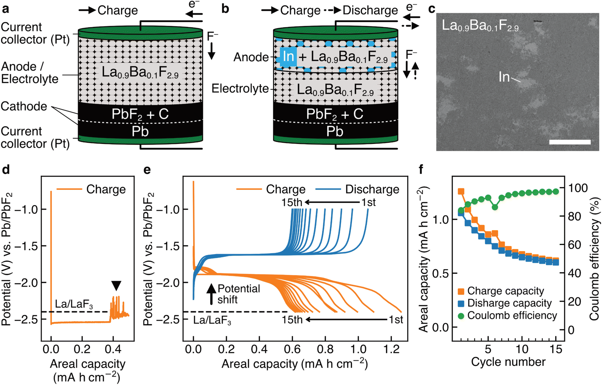 | ||
| Fig. 1 Bulk-type batteries without and with In in the anode. (a) Schematic of a fluoride-ion battery with a pressed powder La0.9Ba0.1F2.9 anode. (b) Schematic of a fluoride-ion battery with an (In + La0.9Ba0.1F2.9) composite anode. (c) Backscattered electron image of the (In + La0.9Ba0.1F2.9) composite anode. (d) Charge curve of a battery with the structure shown in (a). (e) Charge and discharge curves of a battery with the structure shown in (b). (f) Charge capacities, discharge capacities, and coulomb efficiencies obtained from (e). The scale bar in (c) is 50 μm. | ||
Thin-film-type batteries made for STEM analysis
To elucidate the specific redox reactions at In-introduced composite anodes by STEM, we fabricated thin-film-type batteries (see Methods). A schematic of the structure is shown in Fig. 2a, which can be regarded as comprising an (In + LaF3) composite anode, a LaF3 electrolyte, and a (Pb + PbF2) cathode in a discharged state. Please note that, in this configuration, LaF3 is expected to simultaneously serve as both anode and electrolyte materials, akin to the role of La0.9Ba0.1F2.9 in the aforementioned bulk-type batteries. It is also notable that, because LaF3 is not an electron conductor, the defluorination of LaF3 during charge is expected to initiate at the interface with In. The In film for the anode was sputtered on a single-crystal LaF3 substrate using a direct current sputtering technique, as shown in the annular dark-field (ADF) STEM image in Fig. 2b. Fig. 2c shows the charge and discharge curves of the battery with the structure shown in Fig. 2a. The average potentials in the capacity range between 5.0 and 10.0 μA h cm−2 during charge and discharge are −1.89 and −1.68 V vs. Pb/PbF2, respectively. Therefore, the RP of the (In + LaF3) anode is estimated to be −1.79 V vs. Pb/PbF2. Considering that the RP of LaF3 is −2.41 V vs. Pb/PbF2, we can see that the potential shift (0.62 V) is reproduced by thin-film-type batteries.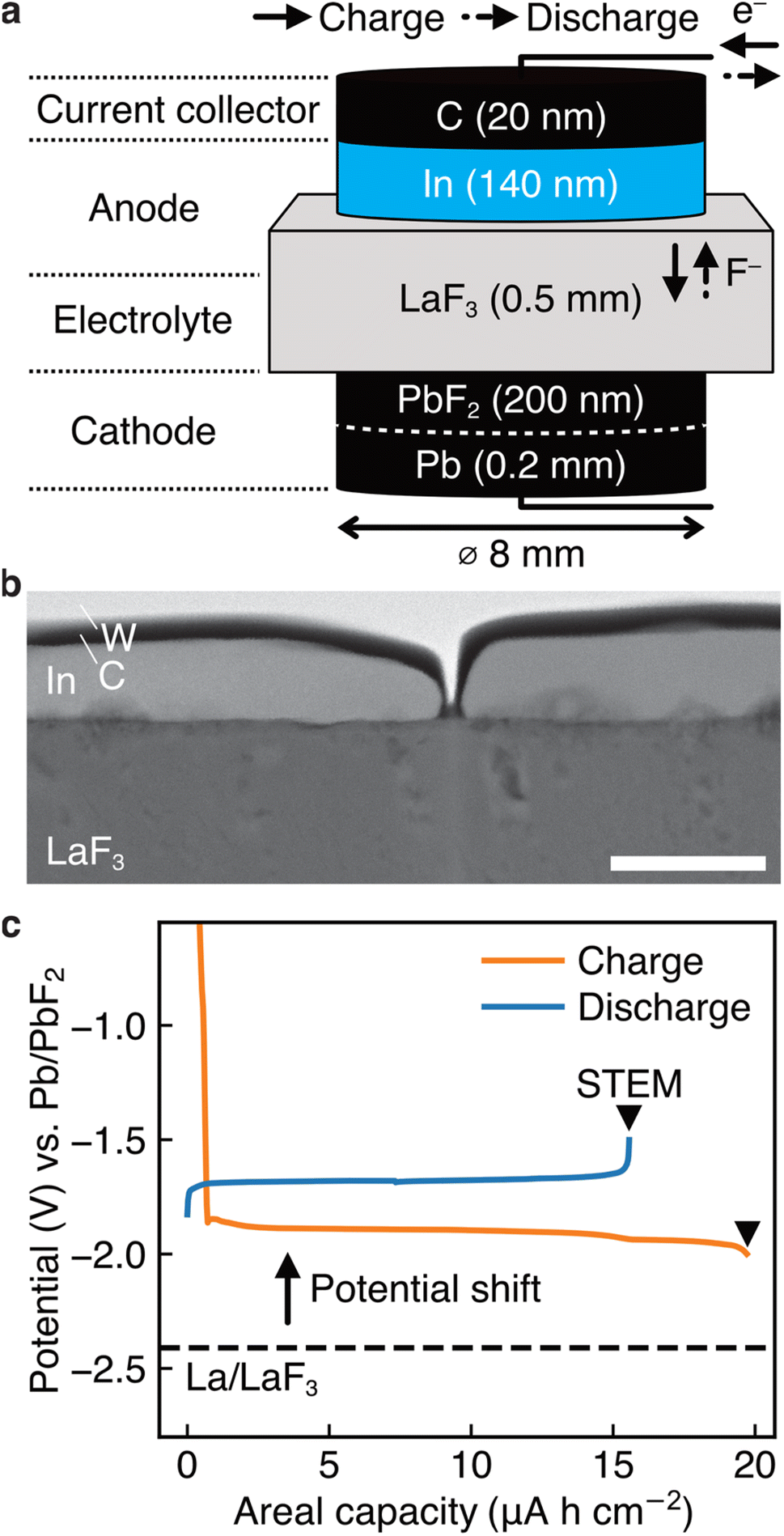 | ||
| Fig. 2 Thin-film-type batteries made for STEM analysis. (a) Schematic of the structure of our thin-film-type batteries. This structure is regarded to have an (In + LaF3) composite anode, a LaF3 electrolyte, and a (Pb + PbF2) cathode. (b) ADF STEM image obtained from the anode of a pristine battery, where W was deposited during the sample thinning process by a focused ion beam technique. (c) Charge and discharge curves of a battery with the structure shown in (a), where the magnitude of the shift in the RP is estimated to be 0.62 V. The scale bar in (b) is 200 nm. | ||
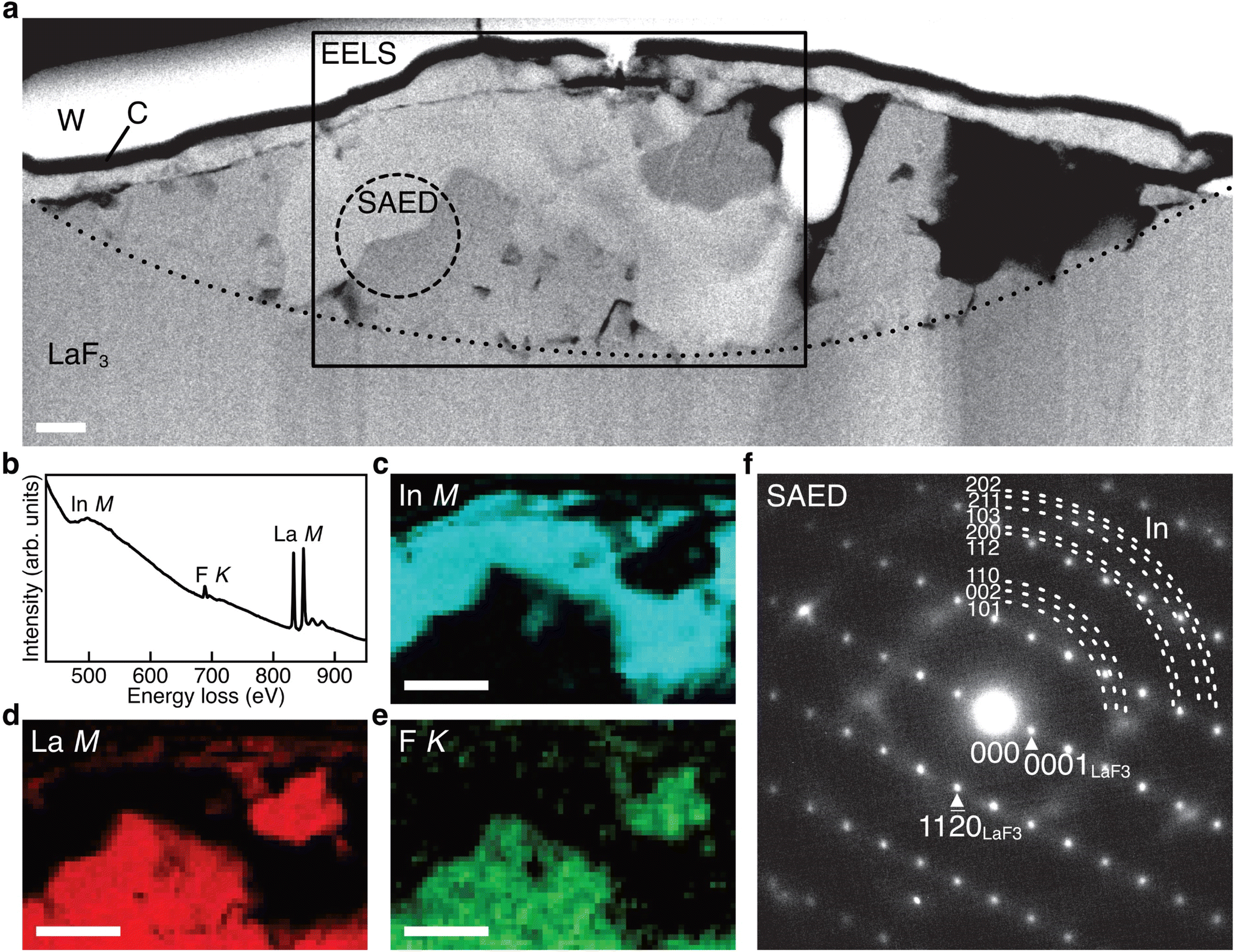
(In + LaF3) anode after charge
Fig. 3a shows the ADF STEM image of the anode after charging. We can observe a product in the region enclosed by the open rectangle. Fig. 3b shows the electron energy-loss spectroscopy (EELS) spectrum obtained from the rectangular region, and we can observe the In M-, F K-, and La M-edges. The In M-edge is a little hard to observe but is detected as a difference from the power-law background. Fig. 3c–e shows the intensity maps of these edges, and we can observe that the product contains In and La, not F. The absence of F indicates that the product was generated by defluorination during the charging process. Both the In M- and La M-edge maps show a relatively uniform distribution within the product, suggesting that these elements form an intermetallic compound. Fig. 3f shows an overlay of the composition maps of In, La, and F calculated from the intensity maps. The majority of the product showed a composition of In![[thin space (1/6-em)]](https://www.rsc.org/images/entities/char_2009.gif) :La = 3:1, while the interfacial region between the product and the LaF3 substrate had a slightly La-rich composition. Fig. 3g shows a selected-area electron diffraction (SAED) pattern obtained from the product, where most reflections can be assigned to In3La, as indicated by the dashed arcs, which is consistent with the composition analysis. The presence of In3La is easier to see in Fig. 3h, which shows a one-dimensional profile obtained by rotationally averaging the two-dimensional intensity distribution shown in Fig. 3g. For reference, Fig. 3h shows the calculated X-ray powder diffraction profiles of In3La,45 In,46 and La.47 As shown by the 220 and 311 reflections of In3La, the profile is consistent with In3La, rather than In and La. These results indicate that an In–La alloy was formed during the charging process, and the dominant phase was In3La. The ideal reaction in the charging process can be written as follows:
:La = 3:1, while the interfacial region between the product and the LaF3 substrate had a slightly La-rich composition. Fig. 3g shows a selected-area electron diffraction (SAED) pattern obtained from the product, where most reflections can be assigned to In3La, as indicated by the dashed arcs, which is consistent with the composition analysis. The presence of In3La is easier to see in Fig. 3h, which shows a one-dimensional profile obtained by rotationally averaging the two-dimensional intensity distribution shown in Fig. 3g. For reference, Fig. 3h shows the calculated X-ray powder diffraction profiles of In3La,45 In,46 and La.47 As shown by the 220 and 311 reflections of In3La, the profile is consistent with In3La, rather than In and La. These results indicate that an In–La alloy was formed during the charging process, and the dominant phase was In3La. The ideal reaction in the charging process can be written as follows:when assuming the above reaction, the expected areal capacity is about 24 μA h cm−2, based on the thickness of the pristine In film (140 nm). This value is comparable to the experimental value of 20 μA h cm−2. It is worth noting that, considering the shape of the alloy product in Fig. 3a, its formation process may have proceeded through initial nucleation followed by subsequent growth.
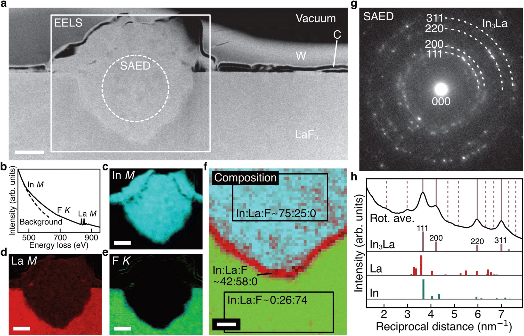 | ||
| Fig. 3 STEM data obtained from the (In + LaF3) anode after charge. (a) ADF STEM image obtained from the anode of a charged battery. (b–e) EELS spectrum and In M-, La M-, and F K-edge intensity maps obtained from the rectangle region in (a). (f) Overlay of composition maps of In, La, and F, which are calculated from (c)–(e). (g) SAED pattern obtained from the dashed circle region in (a). (h) One-dimensional intensity profile obtained by rotationally averaging the SAED pattern in (g), together with calculated X-ray powder diffraction profiles of In3La, La, and In. The vertical lines indicate the reflection positions of In3La, where the solid lines and dashed lines indicate the reflection positions whose calculated intensities are beyond and below 5% of the maximum intensity (the intensity of the 111 reflection), respectively. The scale bars in (a) and (c)–(e) are 500 nm. The scale bar in (f) is 200 nm. | ||
(In + LaF3) anode after one cycle
Fig. 4a shows the ADF STEM image of the anode after one cycle. We can observe a slightly complicated microstructure above the dotted curve, which is recognized as a reaction region during the cycle. Fig. 4b shows the EELS spectrum obtained from the rectangular region in Fig. 4a, and Fig. 4c–e shows the intensity maps of the In M-, La M-, and F K-edges, respectively. We can observe that almost the same region is bright in the F K- and La M-edge intensity maps, whereas the In M- and La M-edge intensities show complementary distributions. This indicates that La and F are in the form of a compound, whereas La and In are spatially separated. That is, the In–La alloy formed during the charging process is decomposed back to In and LaF3 during the discharging process. This interpretation is supported by the SAED pattern shown in Fig. 4f, which was obtained from the dashed circle region shown in Fig. 4a. The regularly arranged diffraction spots and slightly diffused reflections were assigned to LaF3 and In, respectively. Based on these results, the redox reactions of the (In + LaF3) anode are summarized as follows: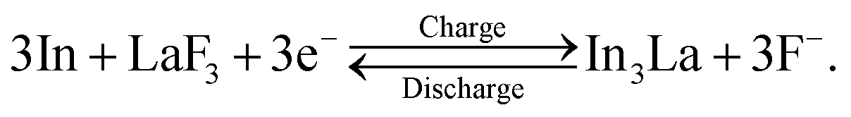
 | ||
| Fig. 4 STEM data obtained from the (In + LaF3) anode after one cycle. (a) ADF STEM image obtained from the anode of a battery after one cycle. (b–e) EELS spectrum and In M-, La M-, and F K-edge intensity maps obtained from the rectangle region in (a). (f) SAED pattern obtained from the dashed circle region in (a). The scale bar in (a) is 200 nm and the scale bars in (c)–(e) are 500 nm. | ||
The aforementioned reactions were repeated over multiple cycles, although the microstructure became increasingly complicated (see Note S1 and Fig. S1–S5 in the ESI†).
Discussion
The STEM results are schematically shown in Fig. 5a. Here, we discuss how alloy formation and phase separation are related to the positive shift in the RP. We consider the electromotive force (EMF), E, because the positive shift in the RP of the anode is interpreted as a decrease in E. Generally, E can be written as E = –ΔG/nF, where ΔG is the difference in the Gibbs free energy before and after discharging, n is the number of moles of electrons involved in the reaction, and F is the Faraday constant.48 In the present case, considering that Pb/PbF2 conversion reactions occur at the cathode, –ΔG/n can be written as follows:| –ΔG/n = {1/3 × G(In3La) + 1/2 × G(PbF2)} – {G(In) + 1/3 × G(LaF3) + 1/2 × G(Pb)}, |
| –ΔG/n = [{1/3 × G(La) + 1/2 × G(PbF2)} – {1/3 × G(LaF3) + 1/2 × G(Pb)}] + [1/3 × {G(In3La) – G(La) – 3 G(In)}]. |
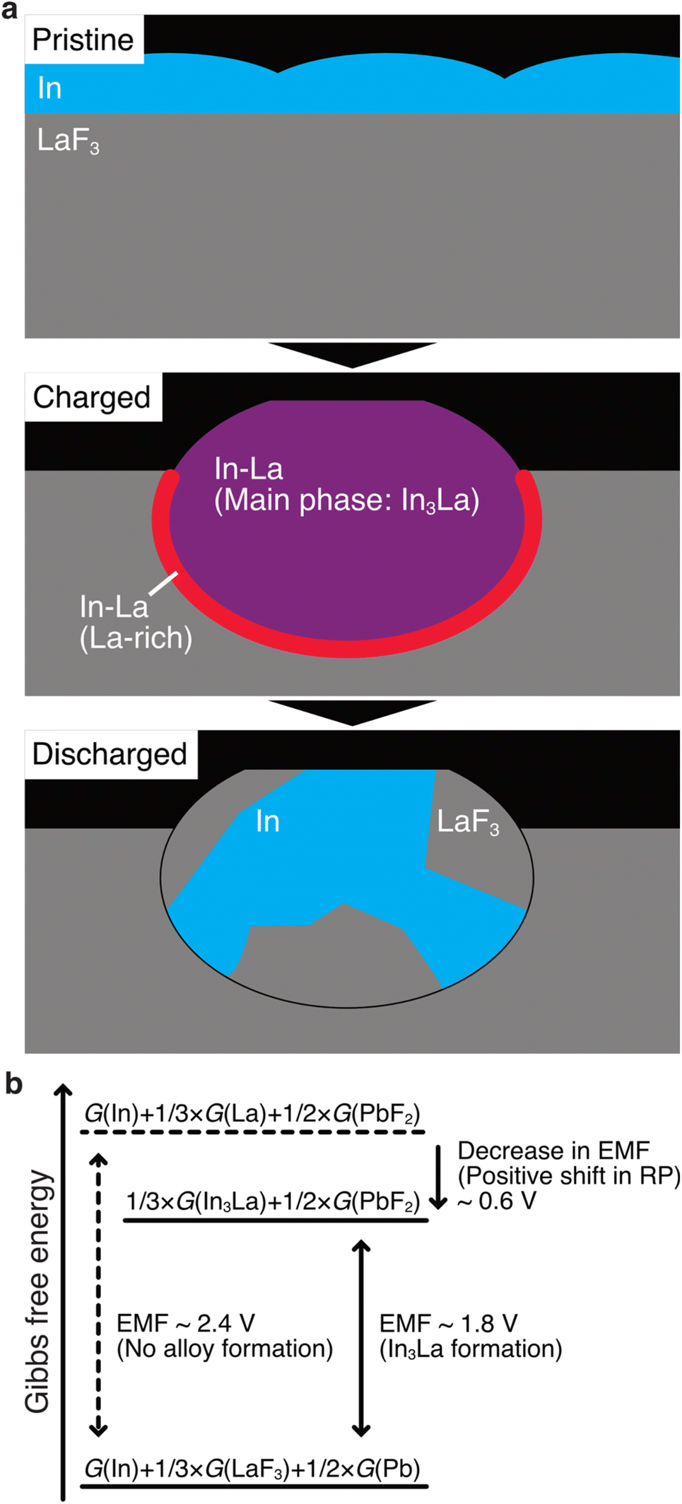 | ||
| Fig. 5 Schematics for the discussion on the potential shift. (a) The microstructure evolution of the (In + LaF3) composite anode. (b) Magnitudes of the Gibbs free energies for the discharged state, charged state with no alloy formation, and charged state with In3La formation. | ||
The terms in the first square brackets can be interpreted as –ΔG/n when only LaF3 contributes to the redox reactions at the anode (no alloy forms), and the terms in the second square brackets can be interpreted as modulation by In3La formation. Because In3La is a thermodynamically stable phase,49 the terms in the second brackets give a negative value, and then –ΔG/n takes a lower value than in the case of no alloy formation. Because the internal energy of In3La formation is calculated to be −0.476 (eV per atom) based on the generalized gradient approximation,50 the value of the second brackets is estimated to be −0.63 × F (J) by neglecting the difference between the Gibbs free energy and internal energy. This approximation is plausible because Δp and ΔT are zero in ΔG = ΔU + pΔV + VΔp – TΔS – SΔT (U: internal energy, p: pressure, V: volume, T: temperature, S: entropy) because the temperature and pressure are constant. ΔV should be small because In, La, and In3La are solids, and ΔS can also be small because In3La is an ordered phase. Based on this value, the magnitude of the potential shift is estimated to be 0.63 V, which is consistent with the experimentally estimated value of 0.62 V. This understanding is schematically summarized in Fig. 5b.
According to the above discussion, RP should be shifted positively when any thermodynamically stable intermetallic phase is formed. Therefore, there is a question why the observed phase is In3La, not a different intermetallic phase in the In–La alloy system, such as In2La and InLa.49 When the defluorination process starts at the anode, there is plenty of In; therefore, it is reasonable that the In-richest intermetallic phase in the In–La alloy system, In3La, is formed. The In3La formation is also justified in terms of the calculated formation energies50 and the expected potential shifts for the intermetallic phases in the In–La system (see Table S1 in the ESI†). Here, it is notable that the melting temperature of In3La (1409 K) is 3.3 times that of In (430 K),49 and the diffusivity of atoms in In3La may be lower than In by more than several orders, considering several known cases of pure metals and intermetallic phases.51 Therefore, after In3La is formed, the formation of another intermetallic phase would be difficult, even if it is preferable in terms of Gibbs free energy. This interpretation is consistent with Fig. 3f, where only a small La-rich region is observed between the In3La and LaF3 regions.
Because the cathodic limits of many electrolytes, including the LaF3 electrolyte (−2.4 vs. Pb/PbF2 (ref. 18 and 19)), are below −1.8 vs. Pb/PbF2,6,9,22,36 the replacement of LaF3 anodes with (In + LaF3) anodes would considerably increase the number of available electrolytes. Nevertheless, it would also be possible to replace In and LaF3 with other materials for further development of the anode (for example, obtaining higher energy densities or increasing further the number of available electrolytes) because many alloy systems have intermetallic phases. Our results propose several guidelines to explore the combinations of M (metals such as In) and M′Fx (metal fluorides such as LaF3). (i) The M–M′ alloy system has a thermally stable intermetallic phase. (ii) The first candidate for the formed phase is the M-richest intermetallic phase. Therefore, it is efficient to start with the M-richest intermetallic phase to estimate the potential shift and capacity. (iii) The magnitude of the potential shift can be roughly estimated from the internal energies of the formation of intermetallic phases, many of which can be easily accessed on the web.50 More precise estimations can be obtained using Gibbs free energies of formation. (iv) The lower the melting temperature of M, the better because the diffusivity of atoms tends to be high when the melting temperature is low, which should be an important factor in utilizing alloy formation during charging. Considering the above guidelines, for example, replacing In in (In + LaF3) anodes with Al has a chance to increase gravimetric energy density: based on the Al-richest intermetallic phase in the Al–La alloy system, Al11La3,52,53 the magnitude of the potential shift is calculated to be around 0.6 V, which is comparable to the case of In3La, while Al is much lighter than In. Future work will focus on exploring more practically favorable combinations of M and M′Fx.
We recognize the necessity of suppressing the capacity fading shown in Fig. 1e and f. Based on the results of the STEM analysis conducted on cycled batteries (see Fig. S2 and S3 in the ESI†), we infer that the causes of capacity fading include (i) the oxidation and hydration of La due to residual oxygen gas and moisture, (ii) the deterioration of physical contact among the anode materials, originating from the volume change between the (In + LaF3) state and In3La, and (iii) the coarsening of In, which may increase the amount of unreacted In. We believe that it is possible to mitigate the first cause by improving the vacuum during charge–discharge tests, and the second and third causes by optimizing the dispersion of In during the anode fabrication process and the temperature during charge–discharge tests. Future work will focus on suppressing capacity fading, as well as enhancing the fluoride-ion conductivity of electrolytes for room temperature operation.
In summary, we have shown that the RPs of (In + LaF3-based material) composite anodes are higher than the RP of La/LaF3 by 0.6 V, which can prevent electrolyte decomposition. Using STEM, the positive shift in the RP has been attributed to alloy formation and phase separation accompanying the defluorination and fluorination reactions of LaF3, which decreases the difference in the Gibbs free energy between the discharged and charged states, weakening the EMF and resulting in a positive shift in the RP. The obtained results will provide a method to control the RPs of fluoride-ion battery anodes via reversible alloy formation, which is likely to considerably increase the number of available electrolytes. We believe that our findings provide a step towards developing practical fluoride-ion batteries.
Methods
Bulk-type batteries
La0.9Ba0.1F2.9 was synthesized by the mechanical milling of LaF3 (99.9%, Kojundo Chemical Laboratory Co., Ltd.) and BaF2 (99.9%, Kojundo Chemical Laboratory Co., Ltd.) at 600 rpm for 3 h under an Ar atmosphere, followed by annealing at 873 K for 10 h. (In + La0.9Ba0.1F2.9) composite powder was prepared from 200 mg of In powder (99.99%, Kojundo Chemical Laboratory Co., Ltd.) and 800 mg of the La0.9Ba0.1F2.9 powder via mechanical milling at 100 rpm for 10 h. (PbF2 + C) composite powder was prepared from 950 mg of PbF2 powder (99.9%, Kojundo Chemical Laboratory Co., Ltd.) and 50 mg of acetylene black powder (Denki Kagaku Kogyo) via mechanical milling at 600 rpm for 3 h. A sheet of Pt foil (99.99%, Furuya Metal Co., Ltd.) as the negative current collector, 30 mg of the (In + La0.9Ba0.1F2.9) powder, 200 mg of the La0.9Ba0.1F2.9 powder, 50 mg of the (PbF2 + C) powder, a sheet of Pb foil (99.9%, Nilaco Corp.), and a sheet of Pt foil as the positive current collector were pressed together at a pressure of 392 MPa into pellets with a diameter of 11.28 mm. The typical thicknesses of these six materials were 20, 50, 330, 90, 200, and 20 μm. For comparison, another type of pellets was also prepared, in which the (In + La0.9Ba0.1F2.9) composite was excluded. The charge and discharge tests were performed in galvanostatic mode using a VMP3 potentiostat (BioLogic) at 413 K with a current of 0.1 mA in a vacuum (1.0 × 10⁻³ Pa). Assuming the reversible formation of In3La, the C-rate was approximately 0.07C. The capacities were normalized by the area of the current collectors (1.00 cm2).Thin-film-type batteries
A thin film of In with a thickness of 140 nm and a diameter of 8 mm was sputtered on a 10 mm × 10 mm × 0.5 mm LaF3 substrate (Pier Optics Co., Ltd.) by direct current sputtering. A thin film of carbon with a thickness of 20 nm and diameter of 8 mm was sputtered on the In film as a current collector. On the other side of the LaF3 substrate, a thin film of PbF2 with a thickness of 200 nm and diameter of 8 mm was sputtered by radio frequency sputtering. On the PbF2 film, a sheet of Pb foil (99.9%, Nilaco Corp.) with a thickness of 0.2 mm was attached. The charge and discharge tests were performed in galvanostatic mode with a current of 0.1 μA, using a VMP-300 potentiostat (BioLogic) at 413 K in a vacuum (1.0 × 10⁻⁴ Pa). Assuming the reversible formation of In3La, the C-rate was approximately 0.008C. The capacities were normalized by the area of the carbon film (0.502 cm2).Electron microscopy
The samples were placed under an Ar atmosphere or vacuum during the processes related to STEM using dedicated sample holders (Hitachi High-Tech Corp. and Mel-Build Corp.) to reduce undesirable oxidation and hydration. Electron-transparent thin specimens for STEM were prepared using the focused ion beam technique at 183 K using NB5000 (Hitachi High-Tech Corp.). Electron diffraction patterns, ADF STEM images, and EELS data were obtained using 2400FCS (JEOL Ltd.) operated at 200 kV. For ADF STEM, the probe-forming aperture was 22 mrad, and the inner cutoff semiangle was 58 or 90 mrad. The EELS spectra were obtained using a Continuum spectrometer (Gatan, Inc.), equipped with the 2400FCS microscope. The spectra were recorded in the STEM mode using 0.3 eV per channel, and the energy resolution was 0.9 V (full-width at half-maximum of zero-loss peak). The convergence and collection semiangles were 22 and 58 mrad, respectively. The chemical compositions were calculated from the experimentally obtained intensities of the In M-, La M-, and F K-edges, and the inelastic scattering cross-sections calculated using the Hartree–Slater method.54 All STEM observations were performed at temperatures below 133 K using liquid nitrogen to lower contamination and electron beam damage.Data availability
The experimental data obtained in this study are available from the corresponding authors upon request.Author contributions
K. Nakayama and H. M. are the co-first authors. K. Nakayama contributed to the STEM analysis. H. M. devised the composite anodes and contributed to the charge–discharge tests of the bulk-type batteries. T. N. contributed to the charge–discharge tests of the thin-film-type batteries. K. Noi contributed to the charge–discharge tests of the bulk-type and thin-film-type batteries. Y. S. and S. K. contributed to the STEM analysis. K. S. contributed to the charge–discharge tests of the thin-film-type batteries. H. I., A. K., Y. I., and T. A. directed the study and made suggestions to promote it.Conflicts of interest
H. M. is an inventor on a Japanese patent (P6536538) and United States patents (US 2019/0334202A1, US 10727533B2) related to this study.Acknowledgements
This study was supported by the RISING2 (JPNP16001) and RISING3 (JPNP21006) projects of the New Energy and Industrial Technology Development Organization (NEDO), Japan.References
- Z. Zhu, et al., Rechargeable Batteries for Grid Scale Energy Storage, Chem. Rev., 2022, 122, 16610–16751 CrossRef CAS PubMed.
- J. W. Choi and D. Aurbach, Promise and reality of post-lithium-ion batteries with high energy densities, Nat. Rev. Mater., 2016, 1, 16013 CrossRef CAS.
- Y. Li and J. Lu, Metal–Air Batteries: Will They Be the Future Electrochemical Energy Storage Device of Choice?, ACS Energy Lett., 2017, 2, 1370–1377 CrossRef CAS.
- Q. Xu, et al., Nanostructural Designs for Electrode Materials of Fluoride Ion Batteries, US Pat.2019/0372111A1, 2019 Search PubMed.
- M. A. Reddy and M. Fichtner, Batteries based on fluoride shuttle, J. Mater. Chem., 2011, 21, 17059–17062 RSC.
- V. K. Davis, et al., Room-temperature cycling of metal fluoride electrodes: liquid electrolytes for high-energy fluoride ion cells, Science, 2018, 362, 1144–1148 CrossRef CAS PubMed.
- D. Zhang, et al., Reversible and Fast (De)fluorination of High-Capacity Cu2O Cathode: One Step Toward Practically Applicable All-Solid-State Fluoride-Ion Battery, Adv. Energy Mater., 2021, 11, 2102285 CrossRef CAS.
- F. Gschwind, et al., Fluoride ion batteries: theoretical performance, safety, toxicity, and a combinatorial screening of new electrodes, J. Fluorine Chem., 2016, 182, 76–90 CrossRef CAS.
- M. A. Nowroozi, et al., Fluoride ion batteries – past, present, and future, J. Mater. Chem. A, 2021, 9, 5980–6012 RSC.
- A. W. Xiao, G. Galatolo and M. Pasta, The case for fluoride-ion batteries, Joule, 2021, 5, 2823–2844 CrossRef CAS.
- M. A. Nowroozi, K. Wissel, J. Rohrer, A. R. Munnangi and O. Clemens, LaSrMnO4: Reversible Electrochemical Intercalation of Fluoride Ions in the Context of Fluoride Ion Batteries, Chem. Mater., 2017, 29, 3441–3453 CrossRef CAS.
- Y. Wang, et al., Anion Substitution at Apical Sites of Ruddlesden–Popper-type Cathodes toward High Power Density for All-Solid-State Fluoride-Ion Batteries, Chem. Mater., 2022, 34, 609–616 CrossRef CAS.
- M. A. Nowroozi, S. Ivlev, J. Rohrer and O. Clemens, La2CoO4: a new intercalation based cathode material for fluoride ion batteries with improved cycling stability, J. Mater. Chem. A, 2018, 6, 4658–4669 RSC.
- Y. Wang, et al., Oxyfluoride Cathode for All-Solid-State Fluoride-Ion Batteries with Small Volume Change Using Three-Dimensional Diffusion Paths, Chem. Mater., 2022, 34, 10631–10638 CrossRef CAS.
- T. Tojigamori, et al., Reversible Charge/Discharge Reaction of a Ternary Metal Fluoride, Pb2CuF6: A Highly Conductive Cathode Material for Fluoride-Ion Batteries, ACS Appl. Energy Mater., 2022, 5, 1002–1009 CrossRef CAS.
- K. Nakayama, et al., Fluoride-ion conversion alloy for fluoride-ion batteries, J. Mater. Chem. A, 2022, 10, 3743–3749 RSC.
- L. B. Pankratz, Thermodynamic Properties of Halides, United States Department of the Interior, 1984 Search PubMed.
- H. Nakano, et al., Fluoride-Ion Shuttle Battery with High Volumetric Energy Density, Chem. Mater., 2021, 33, 459–466 CrossRef CAS.
- K. Motohashi, T. Nakamura, Y. Kimura, Y. Uchimoto and K. Amezawa, Influence of microstructures on conductivity in Tysonite-type fluoride ion conductors, Solid State Ionics, 2019, 338, 113–120 CrossRef CAS.
- C. Rongeat, M. Anji Reddy, T. Diemant, R. J. Behm and M. Fichtner, Development of new anode composite materials for fluoride ion batteries, J. Mater. Chem. A, 2014, 2, 20861–20872 RSC.
- F. Gschwind and J. Bastien, Parametric investigation of room-temperature fluoride-ion batteries: assessment of electrolytes, Mg-based anodes, and BiF3-cathodes, J. Mater. Chem. A, 2015, 3, 5628–5634 RSC.
- I. Mohammad and R. Witter, Testing Mg as an anode against BiF3 and SnF2 cathodes for room temperature rechargeable fluoride ion batteries, Mater. Lett., 2019, 244, 159–162 CrossRef CAS.
- M. H. Fawey, et al., First results from in situ transmission electron microscopy studies of all-solid-state fluoride ion batteries, J. Power Sources, 2020, 466, 228283 CrossRef CAS.
- S. Kobayashi, et al., Nanoscale Defluorination Mechanism and Solid Electrolyte Interphase of a MgF2 Anode in Fluoride-Shuttle Batteries, ACS Appl. Energy Mater., 2021, 4, 996–1003 CrossRef CAS.
- D. T. Thieu, et al., CuF2 as Reversible Cathode for Fluoride Ion Batteries, Adv. Funct. Mater., 2017, 27, 1701051 CrossRef.
- T. Yoshinari, et al., Kinetic analysis and alloy designs for metal/metal fluorides toward high rate capability for all-solid-state fluoride-ion batteries, J. Mater. Chem. A, 2021, 9, 7018–7024 RSC.
- D. Zhang, et al., Understanding the reaction mechanism and performances of 3d transition metal cathodes for all-solid-state fluoride ion batteries, J. Mater. Chem. A, 2021, 9, 406–412 RSC.
- D. Zhang, et al., Cu–Pb Nanocomposite Cathode Material toward Room-Temperature Cycling for All-Solid-State Fluoride-Ion Batteries, ACS Appl. Energy Mater., 2021, 4, 3352–3357 CrossRef CAS.
- D. Zhang, et al., Rate-Determining Process at Electrode/Electrolyte Interfaces for All-Solid-State Fluoride-Ion Batteries, ACS Appl. Mater. Interfaces, 2021, 13, 30198–30204 CrossRef CAS PubMed.
- P. Molaiyan and R. Witter, Crystal phase and surface defect driven synthesis of Pb1−xSnxF2 solid solution electrolyte for fluoride ion batteries, J. Electroanal. Chem., 2019, 845, 154–159 CrossRef CAS.
- D. S. Park and A. S. Nowick, Ionic conductivity and point defects in pure and doped MnF2 and MgF2 single crystals, J. Phys. Chem. Solids, 1976, 37, 607–617 CrossRef CAS.
- M. Murakami, S. Matsumoto and A. Mineshige, Ionic Conduction in Sr-Doped CeF3 as Studied by 19F NMR and AC Impedance Measurement, J. Phys. Chem. C, 2022, 126, 20135–20142 CrossRef CAS.
- I. C. Stefan, C. P. Jacobson, S. J. Visco and L. C. D. Jonghe, Solid-state electrochemistry of fluoride ionic conductive materials, Electrochem. Soc. 206th Meeting Abs., 2004, p. 1707 Search PubMed.
- I. Mohammad, R. Witter, M. Fichtner and M. A. Reddy, Introducing Interlayer Electrolytes: Toward Room-Temperature High-Potential Solid-State Rechargeable Fluoride Ion Batteries, ACS Appl. Energy Mater., 2019, 2, 1553–1562 CrossRef CAS.
- J. Wang, et al., A Fluoride-Ion-Conducting Solid Electrolyte with Both High Conductivity and Excellent Electrochemical Stability, Small, 2022, 18, 2104508 CrossRef CAS PubMed.
- A. Celik Kucuk, T. Yamanaka and T. Abe, Using siloxane-based liquid electrolytes with high stability for fluoride shuttle batteries, J. Mater. Chem. A, 2020, 8, 22134–22142 RSC.
- K. Okazaki, Y. Uchimoto, T. Abe and Z. Ogumi, Charge–Discharge Behavior of Bismuth in a Liquid Electrolyte for Rechargeable Batteries Based on a Fluoride Shuttle, ACS Energy Lett., 2017, 2, 1460–1464 CrossRef CAS.
- T. Yamamoto, K. Matsumoto, R. Hagiwara and T. Nohira, Room-Temperature Fluoride Shuttle Batteries Based on a Fluorohydrogenate Ionic Liquid Electrolyte, ACS Appl. Energy Mater., 2019, 2, 6153–6157 CrossRef CAS.
- N. H. Bashian, et al., Electrochemical Oxidative Fluorination of an Oxide Perovskite, Chem. Mater., 2021, 33, 5757–5768 CrossRef CAS.
- J. L. Andrews, et al., Room-Temperature Electrochemical Fluoride (De)insertion into CsMnFeF6, ACS Energy Lett., 2022, 7, 2340–2348 CrossRef CAS.
- M. Heise, G. Scholz, A. Düvel, P. Heitjans and E. Kemnitz, Mechanochemical synthesis, structure, and properties of solid solutions of alkaline earth metal fluorides: Ma1−xMbxF2 (M: Ca, Sr, Ba), Solid State Sci., 2016, 60, 65–74 CrossRef CAS.
- N. L. Peterson, Self-diffusion in pure metals, J. Nucl. Mater., 1978, 69–70, 3–37 CrossRef CAS.
- C. Rongeat, M. Anji Reddy, R. Witter and M. Fichtner, Solid Electrolytes for Fluoride Ion Batteries: Ionic Conductivity in Polycrystalline Tysonite-Type Fluorides, ACS Appl. Mater. Interfaces, 2014, 6, 2103–2110 CrossRef CAS PubMed.
- G. Homann, L. Stolz, K. Neuhaus, M. Winter and J. Kasnatscheew, Effective Optimization of High Voltage Solid-State Lithium Batteries by Using Poly(ethylene oxide)-Based Polymer Electrolyte with Semi-Interpenetrating Network, Adv. Funct. Mater., 2020, 30, 2006289 CrossRef CAS.
- C. S. Garde, J. Ray and G. Chandra, Resistivity and thermopower studies on La3X (X=Al, Sn, In, Ru, Ir, Co, Ni, Ge, Ga) systems, J. Alloys Compd., 1993, 198, 165–172 CrossRef CAS.
- E. G. Moshopoulou, R. M. Ibberson, J. L. Sarrao, J. D. Thompson and Z. Fisk, Structure of Ce2RhIn8: an example of complementary use of high-resolution neutron powder diffraction and reciprocal-space mapping to study complex materials, Acta Crystallogr. B, 2006, 62, 173–189 CrossRef CAS PubMed.
- H. Krizek and K. N. R. Taylor, Crystal structure of lanthanum-dysprosium alloys, J. Less Common. Met., 1974, 38, 263–265 CrossRef CAS.
- A. J. Bard, L. R. Faulkner and H. S. White, Electrochemical Methods: Fundamentals and Applications, Wiley, 2022 Search PubMed.
- H. Okamoto, In-La (Indium-Lanthanum), J. Phase Equilib., 2003, 24, 93 CrossRef CAS.
- A. Jain, et al., Commentary: The Materials Project: A materials genome approach to accelerating materials innovation, APL Mater., 2013, 1, 011002 CrossRef.
- H. E. Schaefer, M. A. Müller, W. Sprengel and R. Würschum, Intermetallics: Point Defects, in Encyclopedia of Materials: Science and Technology, ed. K. H. J. Buschow, et al., Elsevier, 2001 Search PubMed.
- H. Okamoto, Al-La (Aluminum-Lanthanum), J. Phase Equilib. Diffus., 2007, 28, 581 CrossRef CAS.
- A. H. Gomes de Mesquita and K. H. J. Buschow, The crystal structure of so-called α-LaAl4 (La3Al11), Acta Crystallogr., 1967, 22, 497–501 CrossRef CAS.
- R. F. Egerton, Electron Energy-Loss Spectroscopy in the Electron Microscope, Springer, US, 2011 Search PubMed.
Footnote |
| † Electronic supplementary information (ESI) available. See DOI: https://doi.org/10.1039/d3ta07038g |
| This journal is © The Royal Society of Chemistry 2024 |