
 Open Access Article
 This Open Access Article is licensed under a Creative Commons Attribution-Non Commercial 3.0 Unported Licence
High performance flexible triboelectric nanogenerators using bio-derived films made of siloxane-modified castor oil†
Kishore K.
Jena‡
 ab,
Bushara
Fatma‡
c,
Sagar S.
Arya‡
a,
Saeed M.
Alhassan
b,
Vincent
Chan
ad,
Anna Maria
Pappa
ad and
Charalampos
Pitsalidis
*cd
ab,
Bushara
Fatma‡
c,
Sagar S.
Arya‡
a,
Saeed M.
Alhassan
b,
Vincent
Chan
ad,
Anna Maria
Pappa
ad and
Charalampos
Pitsalidis
*cd
aDepartment of Biomedical Engineering, Khalifa University, PO Box – 127788, Abu Dhabi, United Arab Emirates
bDepartment of Chemical Engineering, Khalifa University, PO Box – 127788, Abu Dhabi, United Arab Emirates
cDepartment of Physics, Khalifa University, PO Box – 127788, Abu Dhabi, United Arab Emirates. E-mail: Charalampos.pitsalidis@ku.ac.ae
dHealthcare Engineering Innovation Center (HEIC), Khalifa University of Science and Technology, PO Box – 127788, Abu Dhabi, United Arab Emirates
First published on 4th March 2024
Abstract
Triboelectric nanogenerators (TENGs), capable of converting mechanical energy into electricity, are sought to enable self-powered devices reducing reliance on traditional power sources. However, traditional triboelectric materials fall short of meeting the urgent need for sustainable and environmentally friendly energy solutions. Emerging bio-derived triboelectric materials promise a lower environmental footprint than their traditional counterparts, yet predominantly exhibit tribopositive characteristics. This results in a diminished surface potential difference in bio-derived layers, leading to reduced energy output and hindering the development of fully bio-derived TENGs (bio-TENGs). Here we introduce a novel material based on castor oil (CO), synthesized by integrating CO with silane coupling agents through processes like esterification, Michael addition, and free radical polymerization. This synthesis produces a siloxane–CO complex, resulting in bio-derived films with high negative surface potential, ideally suited as a tribonegative layer in bio-TENGs. To estimate their position in the triboelectric series, the CO-based films are paired with a polyimide tribolayer to form a dual-layer TENG. In this configuration, the CO-hybrid film manifests a maximum peak output voltage of approximately 330 V and a power density as high as 450 mW m−2. Further investigation revealed that increasing the VTES concentration in the CO shifts its position in the triboelectric series downwards, enhancing its tribonegative properties. This adjustment allows for the development of a flexible, entirely CO-based TENG (All-CO TENG) capable of generating voltages up to 55 V and a power density of 18 mW m−2. Furthermore, the CO-based TENGs are operated in single electrode mode against various surfaces, highlighting their versatility and applicability.
1. Introduction
Triboelectric nanogenerators (TENGs) are energy harvesting devices that use electrostatic charge generation and contact electrification to harness mechanical energy in the form of electricity.1 TENGs have come a long way since their inception in 2012, being widely explored for energy harvesting and self-powered devices as well as for human–machine interfaces.2 For effective generation of triboelectric charges during contact and separation, it is essential for the materials/surfaces involved to possess a significant disparity in their electron affinity and ionization energy. This discrepancy allows for sufficient charge transfer, resulting in an efficient triboelectricity generation. Additionally, materials with high surface energy tend to exhibit superior charge transfer capabilities, further enhancing their triboelectric performance. This characteristic is observed in a range of high-performing triboelectric materials, including nylon (polyamide), hair, cellulose, polyvinylidene fluoride (PVDF), polydimethylsiloxane (PDMS), polytetrafluoroethylene (PTFE), and many more. As such, these materials have demonstrated their effectiveness in various applications involving TENGs.Conventional TENGs, albeit exhibiting high performance, do not align with the growing demand for sustainability and eco-friendly energy harvesting technologies. Further, they cannot fulfill the requirements of self-powered autonomous bio-devices, notably implantables, as they do not exhibit biocompatibility and biodegradability. Biopolymers or bio-derived triboelectric materials have come to the fore to fill this gap offering reduced environmental impact compared to conventional materials, as well as biocompatibility and biodegradability owing to their polymeric nature.3–6 However, the production of a fully degradable bio-TENG is limited by the availability of biopolymer based tribonegative materials. Owing to the positive surface potential of polysaccharides and protein based-biopolymers, those materials are typically classified as tribo-positive layers.7 Biopolymers have been used both as tribopositive and tribonegative layers aiming to achieve an all-bio TENG, resulting however in small surface potential differences and hence low-performance devices given their positive surface charge.8 The most explored tribonegative materials are PVDF, PDMS, PTFE and fluorinated ethylene propylene (FEP), all synthetic non-degradable and non-recyclable polymers.9,10 The tribonegative nature of all these polymers is associated with the functional groups present at their surface, i.e., halogen containing groups in the case of PVDF, PTFE and FEP and the siloxane group for PDMS. As such, to create a biopolymer-based tribonegative layer, surface chemistry can be used to modify the surface of the biopolymer and introduce negative groups, for example halogens.11,12
Castor oil (CO) is a vegetable oil obtained from the seeds of the castor oil plant (Ricinus communis). While not traditionally used as a triboelectric material, its properties and versatility in synthesis and modification make it a good candidate for the development of an all bio-TENG. Several studies have reported organic–inorganic hybrid materials based on CO,13 for example castor oil-modified isophorone diisocyanate and hybrid diols (based on 3-amino propyl trimethoxy silane and 3-glycidoxy propyl trimethoxy silane) with direct modification of its backbone.14,15 Increasing the siloxane concentration in the hybrid materials results in enhanced mechanical and thermal properties, as well as antibacterial activity, and in vitro hydrolytic degradation. An organosilicon hybrid polyurethane from silane grafted isocyanate and castor oil was reported in another study,16 wherein the silica component in the hybrid material significantly improved the thermal and mechanical properties. A non-leachable antibacterial gelatin film based on silane-functionalized castor oil, wherein the inorganic silicon domain in the organic framework improved the mechanical properties of the hybrid material, has been also recently developed17 highlighting the crucial role of the siloxane group in improving the properties of bio-based hybrid materials.
In this study, we present a new approach for the development of a CO-based TENG using reactive silane modification. Our approach follows a relatively easy synthetic route and is cost-effective and environmentally friendly compared to previous studies abstaining from the use of hazardous chemicals such as isocyanate and sulfur. We perform an in-depth study investigating the impact of silane modification on the films' surface and mechanical characteristics, as well as on their antibacterial properties when tested with Gram-negative and Gram-positive bacterial models. The resulting bio-derived films display a negative surface potential, making them ideal tribonegative layers for use in bio-TENGs. The concentration of the siloxane network in the films is shown to affect the triboelectric performance of the TENGs in line with the change in the surface potential of the CO-films. By precisely adjusting the concentration of the siloxane network, the film's surface potential can be tailored, enabling the fabrication of a bio-TENG made entirely of CO films. Notably, the resulting All-CO TENGs exhibit high performance when operating as double or single-electrode TENGs, thus underlining their potential for applications in wearable or implantable electronic devices.
2. Materials and methods
2.1 Materials
Castor oil, para-aminobenzoic acid (PABA), 3-(trimethoxysilyl)propyl methacrylate (TMSPM), 1,6-hexanediol dimethacrylate (HDM), photo-initiator (2-hydroxy 2-methyl phenyl propane 1-one), p-toluenesulfonic acid (PTSA), boron trifluoride etherate (BF3OEt2) and vinyltriethoxysilane (VTES) were purchased from Aldrich Chemical Co. (Milwaukee, WI, USA). All chemicals were analytical grade and used without further purification.2.2. Synthesis of castor oil-amine-TMSPM
The castor oil-amine-TMSPM hybrid (COAmT) is synthesized in a 100 ml round bottom flask. The synthesis process is carried out by using a magnetic stirrer, a thermometer to maintain the inside temperature of the reaction mixture and a reflux condenser to maintain the reaction mixture content till end of the reaction. Initially, castor oil (0.0021 mol, 2 g) and para-aminobenzoic acid (0.0064 mol, 0.88 g) are charged into a flask and the reaction is maintained in an oil bath at 100 °C for 8 h in the presence of 0.5 wt% (0.014 g) of p-TSA as a catalyst. The mole ratio for castor oil and para-aminobenzoic acid was 1![[thin space (1/6-em)]](https://www.rsc.org/images/entities/char_2009.gif) :3. After 8 h of reaction, calculated amounts of 3-(trimethoxysilyl)propyl methacrylate (TMSPM) and boron trifluoride etherate (BF3OEt2) are added to the above mixture and the reaction is continued for 24 h at 50 °C. The mole ratio of castor oil-amine and TMSPM is 1:6. The molecular weight is calculated theoretically and then the amount of TMSPM (0.0169 mol, 4.22 g) required to enable the reaction is calculated. A 0.5 wt% (0.021 g) BF3OEt2 catalyst is used to enable the Michael addition reaction between the primary amine group and conjugated double bond in TMSPM. This novel material synthesized from castor oil, para-aminobenzoic acid and 3-(trimethoxysilyl)propyl methacrylate is named COAmT. The castor oil-amine-TMSPM synthesis process is presented in Scheme S1.†
:3. After 8 h of reaction, calculated amounts of 3-(trimethoxysilyl)propyl methacrylate (TMSPM) and boron trifluoride etherate (BF3OEt2) are added to the above mixture and the reaction is continued for 24 h at 50 °C. The mole ratio of castor oil-amine and TMSPM is 1:6. The molecular weight is calculated theoretically and then the amount of TMSPM (0.0169 mol, 4.22 g) required to enable the reaction is calculated. A 0.5 wt% (0.021 g) BF3OEt2 catalyst is used to enable the Michael addition reaction between the primary amine group and conjugated double bond in TMSPM. This novel material synthesized from castor oil, para-aminobenzoic acid and 3-(trimethoxysilyl)propyl methacrylate is named COAmT. The castor oil-amine-TMSPM synthesis process is presented in Scheme S1.†
2.3 Synthesis of castor oil-amine-TMSPM-VTES
The synthesis of COAmT is carried out in a round bottom flask and then 1 wt% VTES was added dropwise to the solution at 50 °C under constant stirring at 200 rpm. After completing the addition, the reaction is continued for 2 h at 200 rpm to get a clear solution without any phase separation. The hybrid solution is then transferred to a beaker and stored for the UV curing process. Hybrid samples with 3 wt% and 5 wt% VTES were prepared by the same procedure.2.4 Processing COAmTMS and COAmTMS-VT
During the UV curing process, the hybrid samples are transferred to a small glass vial and then 2 wt% photo-initiator (2-hydroxy 2-methyl phenyl propane 1-one) and 1 wt% 1,6-hexanediol dimethacrylate crosslinker are added. The solutions are then stirred at room temperature for 10 min and subsequently cast on a glass slide of approximately 0.2 mm thickness using the doctor blade technique. The resulting coated films are left to dry for 30 min followed by UV exposure for 1 min. For the UV process, a medium pressure mercury vapor lamp (2.66 W cm−2) is used (Lab cure Unit-Wallace Knight, UK). Samples prepared from 1 wt% VTES, 3 wt% VTES and 5 wt% VTES are named COAmTMS-VT-1, COAmTMS-VT-3 and COAmTMS-VT-5. Samples prepared without VTES via UV curing using 2 wt% photo-initiator (2-hydroxy 2-methyl phenyl propane 1-one) and 1 wt% 1,6-hexanediol dimethacrylate crosslinker are named COAmTMS. The curing process involved both thermal and UV treatment. The unreacted unsaturated bonds are then inter-crosslinked via a free radical mechanism, hydrolysis, and condensation reactions inside the UV chamber. Fig. 1(a) and (b) show the structural design and the process steps involved in the synthesis of the COAmTMS-VT material and films. Initially, OH groups in the CO react with the acid group of PABA, resulting in the formation of an ester bond. Then, NH2 terminated groups react with the unsaturated silane coupling agent (TMSPM) and in the last step VTES reacts with the silane groups and unsaturated bonds of the core molecules during UV and moisture curing processes. Two repeating units are possible during this synthetic route. (a) Unsaturated bonds (–CH![[double bond, length as m-dash]](https://www.rsc.org/images/entities/char_e001.gif) CH–, CCH2 and CH2CH–) to saturated crosslink (CH–CH2– and –CH2–CH2–) and (b) Si–O–Si siloxane groups. The complete synthetic parts are shown in Schemes S1 and S2.† The instrumental material/film characterization techniques are reported in the ESI (Section S1.1).†
CH–, CCH2 and CH2CH–) to saturated crosslink (CH–CH2– and –CH2–CH2–) and (b) Si–O–Si siloxane groups. The complete synthetic parts are shown in Schemes S1 and S2.† The instrumental material/film characterization techniques are reported in the ESI (Section S1.1).†
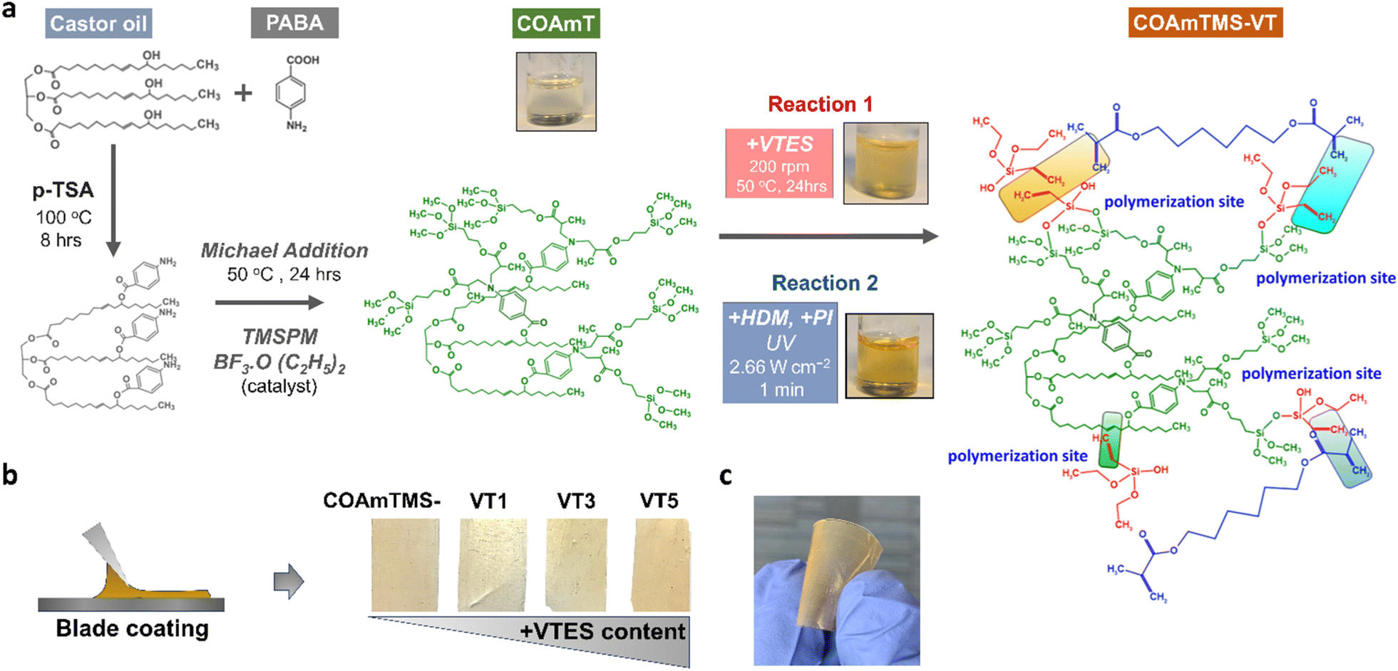 | ||
| Fig. 1 (a) Chemical structures showing the different reaction steps and the synthesis route of the COAmTMS-VT solutions. Inset photographs show the resulting solutions (in a beaker) during the different processing steps. (b) Photographs of self-standing COAmTMS films with different amounts of VTES prepared via blade coating (COAmTMS, COAmTMS-VT-1, COAmTMS-VT-3, and COAmTMS-VT-5). (c) Photograph of a flexible COAmTMS film. | ||
2.5 Bacteria and culture conditions
Pseudomonas aeruginosa and Staphylococcus aureus are used as Gram-negative and Gram-positive bacteria, respectively. Bacteria are inoculated from – 20 °C glycerol stocks and grown overnight in Luria Bertani (LB) broth. Next day, the monocultures and co-culture of P. aeruginosa and S. aureus are prepared separately by centrifuging overnight grown bacteria at 3000 g for 5 min at 4 °C.18 The bacteria cell pellets are resuspended in 1 mL of LB and the OD at 600 nm is adjust to 0.1 (±0.05; equivalent to the McFarland standard, i.e., 1 × 10⁸ CFU mL−1) for biofilm assay. For co-culture, the bacterial cultures adjusted to 0.1 OD are mixed in a 1:1 ratio and used for biofilm assay.
2.6 Biofilm assays
Discs of 6 mm are obtained by punching holes in the films. The discs are sterilized via incubation in 70% ethanol for 15 min and subsequently washed with sterile PBS. Then they are placed in a 96-well plate horizontally and vertically, followed by the addition of 250 μL bacterial cultures adjusted to 0.1 OD to each well. The plates are incubated overnight at 37 °C. Following incubation, media and non-adherent cells are removed and the discs are gently washed with PBS. The bacterial biomass adhered to the discs is determined by staining with 0.5% crystal violet (v/v), which is re-solubilized with 7% acetic acid (v/v) and its concentration is determined by recording the absorbance at 595 nm. Scanning electron microscopy (SEM) is performed by fixing the bacteria on the discs with 2% glutaraldehyde for 1 h, followed by sequential dehydration with 60%, 70%, 80% 90% and 100% ethanol for 10 min each. The discs are then observed under a SEM.2.7 TENG device fabrication and characterization
The fabricated CO-based films (COAmTMS, COAmTMS-VT-1, COAmTMS-VT-3, and COAmTMS-VT-5) are used as triboelectric layers against a 0.05 mm polyimide film (PI) (GoodFellow, USA). To construct the triboelectric pair, CO-based films and PI films are placed on top of aluminium (Al) and copper (Cu) tape, respectively, serving as electrodes. The triboelectric components are then attached to PET (polyethylene terephthalate) substrates with the triboelectric layers facing one another to create a TENG with an active area of 30 × 30 mm2. By attaching both triboelectric layers to a self-automated setup, the open circuit voltage output of the TENGs is obtained using a digital oscilloscope (Tektronics TBS 1072B) in response to the compressive force with a controlled frequency of 1 Hz and a spacing of 2 cm between layers. In the case of the All-CO TENG, COAmTMS and COAmTMS-VT-5 films along with Al are used as the triboelectric pair.3. Results and discussion
3.1 Synthetic mechanisms
In this work, esterification, Michael addition, radical polymerization, hydrolysis, and condensation reaction mechanisms are involved in the development of the modified CO-materials. Organic and inorganic phases are connected through Michael addition, sol–gel reaction and radical polymerization. In Michael addition, the primary amine group of PABA reacts with the conjugated double bond of TMSPM molecules at 50 °C. The presence of methoxy groups in TMSPM silane undergoes hydrolysis to form silanol. With the addition of VTES to the hybrid COAmT, the silane groups of VTES and TMSPM are interconnected and condensed forming a siloxane network. Increasing the concentration of VTES results in a more extensive crosslinking within the siloxane matrix of the hybrid material, increasing the siloxane concentration. Another possible free radical reaction is also observed between the vinyl group of VTES and the unsaturated bonds of TMSPM, which further increases the organic and inorganic phase compatibility, thus forming a unique hybrid phase. O–CO (ester), Si–O–C (from the reaction between the unreacted OH group of CO and Si–OH/Si–OCH3/Si-OC2H5), and Si–O–Si siloxane networks (between Si–OH and Si–OH, as well as Si–OH and Si–OCH3/O–C2H5) are the primary chemical linkages in the hybrid that enhance the film-forming properties, hydrophobicity, and strength of the materials. These chemical conformations have been also confirmed by XPS and FTIR analyses, as illustrated in Fig. 2.
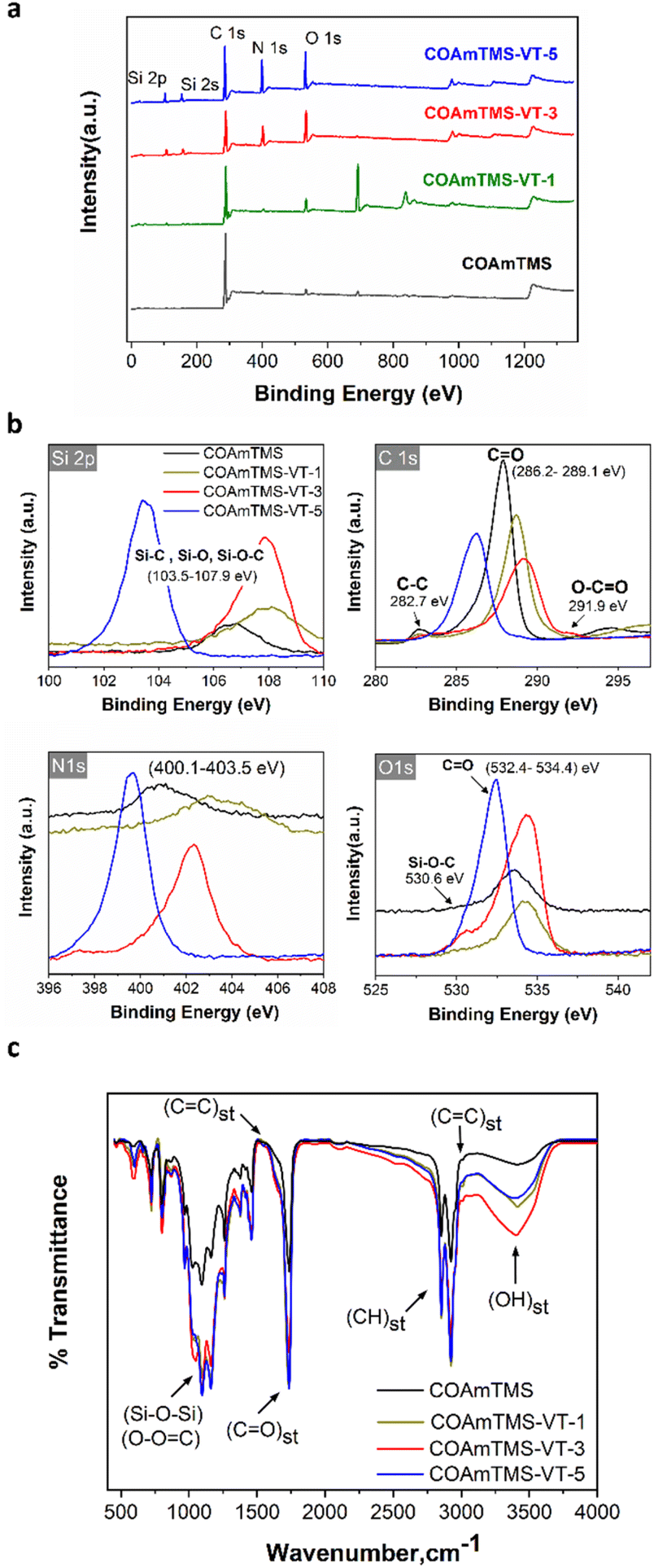 | ||
| Fig. 2 (a) Full scale XPS survey spectrum of the CO-based films and (b) the associated Si2p, C1s, N1s, and O1s XPS spectra. (c) Comparative FTIR spectra of the various CO-based films. | ||
3.2 COAmTMS film characterization
Fig. 2(a) shows the XPS survey spectra of COAmTMS, COAmTMS-VT-1, COAmTMS-VT-3, and COAmTMS-VT-5 hybrid materials. The surface bonding state of the COAmTMS-VT samples reveals the presence of C, N, O and Si elements. A pronounced peak observed in the XPS of CoAmTMS-VT-1 (∼700 eV) is most likely associated with F groups that are present in the catalyst (BF3–OEt) used during the sol-gel process. The existence of C–C (282.7 eV, aromatic rings), CO (286.2–289.1 eV) and O–CO (291.9 eV) can be seen in Fig. 2(b).19,20 Furthermore, the apparent peaks at 400.1–403.5 eV are associated with N1s, while the 530.6 eV and 534.4 eV peaks are assigned to absorbed oxygen, as presented in the O1s graph. Si2p binding energy peaks are also identified between 103.5 and 107.9 eV.21,22 The atomic percentage of Si in COAmTMS, COAmTMS-VT-1, COAmTMS-VT-3, and COAmTMS-VT-5 is estimated to be 0.92, 1.72, 5.01 and 8.49%, respectively confirming the successful incorporation of the siloxane network withing the modified CO materials.
FTIR analysis enables the identification of the characteristic functional groups of the various components in the CO-based films. Fig. 2(c) shows the recorded FTIR spectra of the COAmTMS, COAmTMS-VT-1, COAmTMS-VT-3 and COAmTMS-VT-5 films. The broad peak at 3478 cm−1 corresponds to the –OH stretching vibration band, which can be attributed to the silanol group of the silane coupling agents.23,24 Inter/intra-molecular hydrogen interaction between the –OH groups of the silanol and the ester groups of the CO and the TMSPM chain may influence the width of the –OH peak in all the hybrid materials. The two strong peaks at 2921 cm−1 and 2838 cm−1 are attributed to the vibration of axial deformation of –CH of the methylene group.25 The band at 1761 cm−1 is assigned to the CO stretching of ester compounds, whereas the relatively small peak at 1632 cm−1 indicates the –CC– double bond stretching frequency of long chain fatty acids, VTES, TMSPM and HDM crosslinker.26 This confirms that almost all the unsaturated bonds are interconnected during the UV curing process and Michael addition reaction. The incorporation and covalent linkage formation of VTES in the modified-CO materials are confirmed by the disappearance of CC stretching vibration at 1632 cm−1 and 3019 cm−1. Furthermore, the apparent peaks within the 1000 to 1200 cm−1 range correspond to Si–O–C, Si–O–Si, and Si–OH.25,27–30 As expected, the Si–O–Si stretching intensity increases with the concentration of VTES, most likely due to the formation of a more extensive siloxane network.
To assess the crystalline structure of the synthesized CO-based films, we performed X-ray diffraction measurements. Fig. S1† shows the XRD patterns of COAmTMS, COAmTMS-VT-1, COAmTMS-VT-3, and COAmTMS-VT-5. As shown, all the films exhibit two major peaks at 2θ ∼11.2° and ∼20.4°, respectively. The presence of the two hump-like characteristic profiles in the XRD spectra is indicative of the semicrystalline nature of the COAmTMS-based films.31 Interestingly, the intensity of these peaks tends to decrease with the VTES content in the films, suggesting that upon increasing the siloxane network the amorphous proportion of the siloxane network may disrupt short range ordering in the COAmTMS-based films.
Surface morphology characteristics are obtained by means of SEM as shown in Fig. 3(a). The introduction of the siloxane component imparted a noticeable alteration in the surface topography and texture of the castor oil films. This effect can be attributed to the interaction of siloxane molecules with the castor oil matrix, which promotes the formation of aggregation domains that increase surface heterogeneity. This is also consistent with the AFM measurements of the COAmTMS-VT samples, (Fig. S2†) which show an increase in the RMS roughness value of 5.7, 6.9 and 7.4 nm for the COAmTMS-VT-1, COAmTMS-VT-3 and COAmTMS-VT-5 films, respectively (as reported in Table S1†).
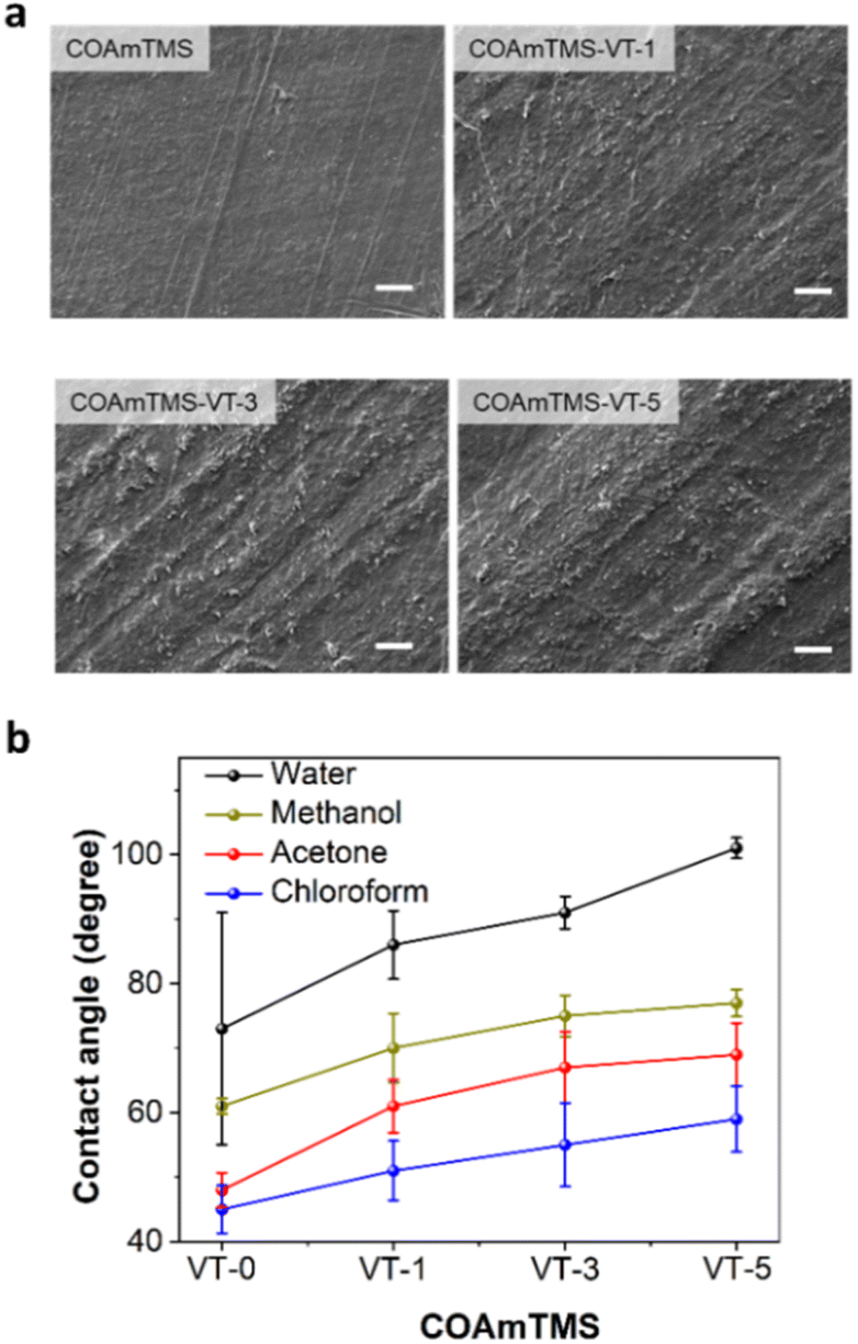 | ||
| Fig. 3 (a) SEM images (scale bar corresponds to 10 μm) and (b) contact angle values for COAmTMS, COAmTMS-VT-1, COAmTMS-VT-3 and COAmTMS-VT-5 films in different polar and nonpolar solvents (water, methanol, acetone and chloroform). | ||
The hydrophobic nature of the COAmTMS-based films is evaluated by means of contact angle measurements. The contact angle of the hybrid films is calculated using various polar and nonpolar solvents, such as water, methanol, acetone and chloroform (see Fig. 3(b)). Following the same trend, the films exhibit an increase in the contact angle values when increasing the VTES content, due to a decrease in the surface energy. Specifically, the pristine COAmTMS film exhibits a contact angle of 73° ± 18, while the COAmTMS-VT-1, COAmTMS-VT-3 and COAmTMS-VT-5 films show values of 86° ± 5.3, 91° ± 2.5 and 101° ± 1.6, respectively. Such an increase can be attributed to the presence of the Si–O–Si network structure in the COAmTMS-based films.27,32,33
Fig. S3† shows the stress–strain curves of COAmTMS, COAmTMS-VT-1, COAmTMS-VT-3 and COAmTMS-VT-5 hybrid materials. The mechanical strength of the hybrid samples is reported in Table S2.† The ultimate tensile strength (UTS) and elongation at break percentage (%) of COAmTMS, COAmTMS-VT-1, COAmTMS-VT-3 and COAmTMS-VT-5 are measured to be 12.9 MPa and 57.6%; 14.4 MPa and 46.2%; 15.6 MPa and 45.6 MPa; 17.5 MPa and 35.2%, respectively. A strong deformation and elongation (%) at break point are observed in the case of pristine COAmTMS. In the presence of VTES, the tensile strength follows an increasing trend while the elongation (%) at break decreases. This can be also attributed to the increase of the siloxane network, which restricts the polymer chain mobility, thus making it more rigid.34
3.3 Bacterial adhesion and biofilm development
Given that TENGs are subjected to frequent physical contact and environmental exposure, they become susceptible to microbial colonization, leading to device degradation and potential health risks. Here, to assess the antimicrobial properties of the fabricated films, a systematic study using P. aeruginosa and S. aureus bacterial models has been carried out.35,36 Both bacteria are assessed in mono- and co-cultures with respect to their attachment to horizontally and vertically placed CO-based films, as shown in Fig. 4(a).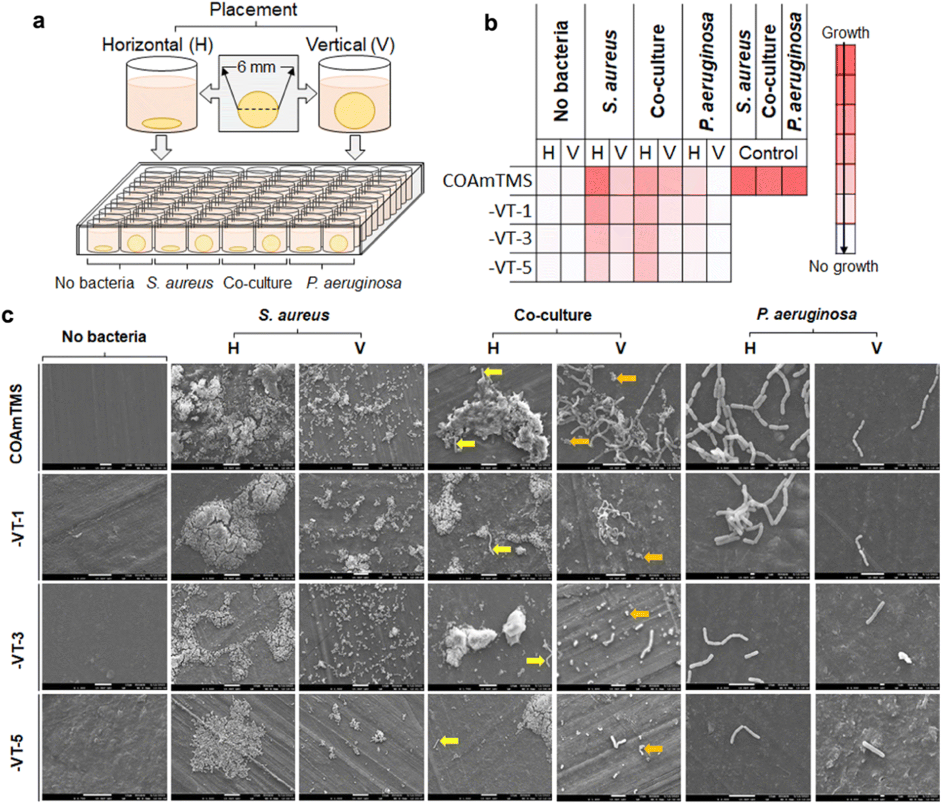 | ||
| Fig. 4 (a) Illustration of the biofilm assay setup. For the assessment of the biofilm/bacteria adhesion, the CO-based films are placed horizontally or vertically. (b) A heatmap graph showing a quantitative estimation of the bacterial growth in both monocultures and co-cultures. (c) SEM images used for the qualitative assessment of the bacterial attachment/growth on the films as monocultures and co-cultures. Yellow arrows pointing to P. aeruginosa cells dominated by S. aureus on horizontally placed discs and orange arrows pointing to S. aureus cells dominated by P. aeruginosa cells on vertically placed discs. (H – horizontal and V – vertical). | ||
The heatmap of Fig. 4(b) summarizes the bacterial attachment and growth under different conditions. S. aureus shows high biofilm forming potential on the pristine COAmTMS films compared to P. aeruginosa, as well as when co-cultured. However, both S. aureus and P. aeruginosa (and their co-culture) are found to gradually decrease with the increase in the VTES concentration and the associated hydrophobicity. This tendency is apparent under both horizontal and vertical conditions, although the attachment of the bacterial cultures to the different samples is more prominent when tested horizontally, as shown in Fig. 4(c). Overall, the bacteria are unable to form biofilms or cling to the COAmTMS-VT films. The effect of the increasing siloxane concentration is more pronounced in P. aeruginosa versus S. aureus, resulting in attenuated growth or adhesion of the bacterium to the surface of the COAmTMS-VT films. Conversely, the antibacterial effects of the films can be augmented by the presence of hydroxyl groups alongside siloxanes, either independently or in synergy with the siloxane network on the film surface.38 These results are consistent with previous reports on siloxane-modified films demonstrating that the increase in the concentration of siloxane improves the antibacterial properties of films. For instance, Jia et al.37 showed that increasing 3-(2-aminoethylamino)propyldimethoxymethylsilane in cationic waterborne polyurethane films enhances the antibacterial activity against Escherichia coli and S. aureus, highlighting the relationship between siloxane content and the antibacterial activity of the films.
3.4 Castor oil-based films as triboelectric layers for TENGs
In order to benchmark COAmTMS as a triboelectric material and position it in the triboelectric series, we initially tested it against a reference tribolayer, such as PI (see Fig. 5(a)). The fabricated COAmTMS-based TENGs are operated in contact-separation mode to generate electricity from mechanical energy. In such a case, electrons move back and forth between the two electrodes affixed to the backside of the triboelectric layers, driven by repeated contact and separation due to contact electrification and electrostatic induction. In the pressed state, the top and bottom layers' friction caused by an external force produces opposing surface charges on the two surfaces. A potential drop between the two back-electrodes is induced by the separation of the two surfaces (releasing state), which releases electrons from one electrode to the other to maintain charge balance. In a fully released state, the potential drop gradually vanishes before equilibrium is reached. The electrons that accumulate on the electrode flow back when the surfaces come back into proximity, producing an inverted output (pressing). Therefore, a steady AC electrical voltage emerges because of the persistent contact and separation between friction layers. | ||
| Fig. 5 (a) Schematic illustration of the device architecture and photographs of the individual triboelectric layers (COAmTMS vs. PI). (b) Graph showing the output voltage of the COAmTMS TENG with COAmTMS and PI as triboelectric layers in response to the intermittent contact and separation of tribo-layers at 1 Hz frequency. (c) Long term operation of the COAmTMS TENG showing the generated output voltage over a period of 30 minutes. (d) Variation in the voltage output and (e) power density of TENGs for various load resistance values (between 10 kΩ and 2 GΩ). (f) KPFM image showing the surface potential of the pristine COAmTMS film. | ||
To characterize the electrical performance of the TENGs, a linear motor with the capability to continuously exert and release force on the device is used. The open circuit voltage of the pristine COAmTMS films is found to be ∼330 V when PI is used as the counter triboelectric frictional layer (Fig. 5(b)). To rule out the possible contribution of parasitic effects on the device performance, both forward and reverse connection modes are tested, as shown in Fig. S4.† In the forward connection (FC), the oscilloscope's positive probe is connected to the COAmTMS film and the negative probe is connected to the PI film, while in the reverse connection (RC) the polarity is reversed. Fig. S5† shows the voltage response of the pristine COAmTMS TENG for a single cycle of press and release in the FC and RC mode. As can be observed, both cases exhibit similar output voltage values, indicating that the generated signals correspond to valid outputs.39,40 The performance stability of the TENG has been assessed by performing a continuous long-term operation of the device. As shown in Fig. 5(c) the TENG appears to maintain its maximum output voltage even after 30 minutes of continuous operation. Fig. 5(d) shows the variations in output voltage for the COAmTMS TENG when subjected to different load resistances, from 10 kΩ to 2 GΩ. This graph demonstrates the rise in the output voltage as the load resistance in the circuit increases. Subsequently, the power output in relation to varying load resistance is calculated, yielding a peak power density of approximately 450 mW m−2 for the COAmTMS TENG, as shown in Fig. 5(e).
Using KPFM we are able to map the 2D surface potential of the pristine COAmTMS films (see Fig. 5(f)). The corresponding histogram with the surface potential variations of the COAmTMS film is presented in Fig. S6.† The film exhibits a negative surface potential, peaking at around −4.9 V and ranging from approximately −4.5 V to −5.3 V, indicating its tribonegative character. Nevertheless, we were unable to obtain a surface potential profile for the COAmTMS-VT film variations, as their surface potential is found to exceed the instrument's range.
3.5 Tribonegative surface modification
Surface charge generation upon friction is based on different factors like the roughness, dielectric properties, and surface functional group of the material.10,40,41 The negative surface potential of the COAmTMS film is associated with its chemical structure. Polydimethylsiloxane (PDMS) is the most prevalent and extensively studied tribonegative material.42–46 The PDMS chemical structure has a siloxane group, which contributes to its tribonegative traits,42 similarly to COAmTMS containing siloxane. Therefore, the difference in the electronegativity between the two-friction layers (COAmTMS containing siloxane and PI) determines the triboelectric charge density on the frictional surface, which is a primary factor affecting the voltage output of the CO-based TENGs.42,47 To enhance the electronegativity of COAmTMS, we increase the concentrations of VTES. This results in the growth of the siloxane network, making the surface more electronegative compared to unmodified COAmTMS. To investigate the impact of varying VTES concentrations on the triboelectric performance of CO-based TENGs, the film variants were measured against a reference triboelectric layer of PI (see Fig. 6(a)). As the VTES content increases, the electronegativity gap between the COAmTMS-VT series and PI narrows, resulting in a decrease in voltage output, as confirmed in Fig. 6(b). Specifically, the output voltage of COAmTMS drops from approximately 330 V to around 265 V, 208 V, and 79 V for VTES concentrations of 1%, 3%, and 5%, respectively. Consequently, the addition of VTES causes COAmTMS to move closer to PI in the triboelectric series. This makes COAmTMS and its VTES-enriched variants viable alternatives to traditional tribonegative materials, such as PDMS and PVDF, with the added advantage of being bioderived. Overall, the performance of our devices ranks among the best performing bio-TENGs with a biopolymer-based negative triboelectric layer (Table S3†). | ||
| Fig. 6 (a) Device structure and the triboelectric series for the various COAmTMS-based films versus PI. (b) Voltage output plot of the TENG made using PI as one tribolayer and COAmTMS, COAmTMS-VT-1, COAmTMS-VT-3 and COAmTMS-VT-5 as the counter tribolayer to investigate the effect of different VTES concentrations. (c) Device structure of the All-CO TENG composed of COAmTMS and COAmTMS-VT-5 tribolayers as highlighted in the triboelectric series. (d) Voltage output plot of the All-CO TENG in the forward and reverse mode. (e) Voltage output and power density plots of the All-CO-TENG for various load resistance values (between 10 kΩ and 2 GΩ). | ||
3.6 Bio-TENG made of an all castor oil-based film (All-CO TENG)
Finally, we have engineered a bio-TENG composed entirely of CO-based tribolayers. Utilizing the data from the previous section, we were able to determine the relative positions of COAmTMS films in the triboelectric series. This enabled us to select the pair that yields the maximum surface potential difference. Specifically, we combined COAmTMS-VT-5, which falls on the more tribonegative end of the triboelectric series, with pristine COAmTMS, which lies on the less tribonegative end. The architecture of the All-CO TENG is schematically illustrated in Fig. 6(c), along with the materials' relative positions in the triboelectric series. The resulting All-CO TENG is found to generate an output voltage of approximately 55 V, as shown in Fig. 6(d). Fig. 6(e) shows the variations in output voltage for the All-CO TENG when subjected to different load resistances, from 10 kΩ to 2 GΩ. This graph demonstrates the rise in the output voltage as the load resistance in the circuit increases. Subsequently, the power output in relation to varying load resistance is calculated, yielding a peak power density of approximately 18 mW m−2.The COAmTMS-VT films are also used in a single-electrode (SE) TENG configuration, a particularly interesting architecture for self-powered electronics and wearable technologies. The COAmTMS-VT-5 film is employed as the active tribolayer against various positive and negative friction layers, such as PET, cCu, PVDF and PI. Fig. S7† shows the generated voltage output upon contact-separation motion in the SE-TENG operation mode. The voltage output is found to be highest (75 V) when PET is used as a friction layer (electrically free of contact) most likely due to its position in the triboelectric series (towards less negative) and the interfacial properties. In contrast, the output voltage is lowest (−17 V) against PI due to a similar polarity and smaller charge differential versus COAmTMS-VT-5.
It's noteworthy that the overall performance of the All-CO TENGs is among the highest recorded for biopolymer-based TENGs in the existing literature, as can be seen in Table S3.† Given these findings, All-CO TENGs have the potential to emerge as important candidates for sustainable and eco-friendly electronic applications.
4. Conclusions
In summary, our work marks the first successful development of a CO-based TENG enhanced with siloxane group modifications. These chemical changes are found to impart significant tribonegative characteristics to the bio-derived CO layer. Particularly, increasing the VTES concentrations enhances these properties by expanding the siloxane network, consequently shifting the material closer to the negative spectrum of the triboelectric series. These modifications were confirmed through the operation of different COAmTMS-VT films against a PI reference layer within a TENG device. Considering the VTES driven shift in the triboelectric series, a combination of COAmTMS and COAmTMS-VT-5 is used to make an All-CO TENG with a voltage output and power density of 55 V and 18 mW m−2, ranking it among the best-performing bio-TENG devices in the literature. To broaden the versatility of our materials, COAmTMS-VT based TENGs are employed in a single electrode mode configuration against various triboelectric layers, achieving a maximum voltage output of 75 V (for PET).Overall, our research highlights the promise of chemically modifying biomaterials to customize triboelectric properties, thereby broadening the design options for TENGs. Considering the limited number of tribonegative biopolymers available, our development represents a significant advancement towards sustainable and eco-friendly energy harvesting. Moreover, our materials can be readily applied to tribopositive surfaces, including skin and textiles, facilitating energy collection for on-body devices and wearable electronics.
Author contributions
BF conceptualized the idea of making a CO-based TENG, designed the device, performed the device related experiments and wrote the manuscript. KJ conceptualized, synthesized and characterized the CO-based bio-derived film and wrote the original draft. SA performed the antibacterial study along with manuscript writing. CP and AM provided the resources and funding acquisition. CP edited the manuscript and supervised the work. All authors discussed, revised and approved the manuscript.Conflicts of interest
There are no conflicts to declare.Acknowledgements
This project is funded by Khalifa University, Abu Dhabi, United Arab Emirates (UAE). CP and BF acknowledge the financial support from Khalifa University under grant code 5032-FSU-2022-007. AMP, VC and KJ acknowledge the financial support from Khalifa University under grant code 8474000477 – ESIG-2023-006. AMP and SA acknowledge the financial support from FSU-2022-009 grant from Khalifa University. AMP, SA and CP acknowledge funding from the Healthcare Engineering Innovation Center (grant number RC2-2018-022) and the Center of Biotechnology (BTC) at Khalifa University. The authors would like also to acknowledge Mr Ajay Singh Chauhan (Junior Technician) and Prof. Ashish Garg (Professor, Department of Sustainable Energy Engineering, IIT Kanpur) for assisting in the acquisition of the KPFM measurements.References
- W.-G. Kim, D.-W. Kim, I.-W. Tcho, J.-K. Kim, M.-S. Kim and Y.-K. Choi, ACS Nano, 2021, 15, 258–287 CrossRef CAS PubMed.
- D. Choi, Y. Lee, Z.-H. Lin, S. Cho, M. Kim, C. K. Ao, S. Soh, C. Sohn, C. K. Jeong and J. Lee, ACS Nano, 2023, 17(12), 11087–11219 CrossRef CAS PubMed.
- N. F. AC Wahab, T. P. Kannan, Z. Mahmood, I. A. Rahman and H. Ismail, Recent Pat. Mater. Sci., 2017, 10, 50–59 Search PubMed.
- L. Ding, X. Li, L. Hu, Y. Zhang, Y. Jiang, Z. Mao, H. Xu, B. Wang, X. Feng and X. Sui, Carbohydr. Polym., 2020, 233, 115859 CrossRef CAS PubMed.
- G. Dandegaonkar, A. Ahmed, L. Sun, B. Adak and S. Mukhopadhyay, Mater. Adv., 2022, 3, 3766–3783 RSC.
- L. He, C. Zhang, B. Zhang, Y. Gao, W. Yuan, X. Li, L. Zhou, Z. Zhao, Z. L. Wang and J. Wang, Nano Energy, 2023, 108, 108244 CrossRef CAS.
- L. Bai, Q. Li, Y. Yang, S. Ling, H. Yu, S. Liu, J. Li and W. Chen, Research, 2021, 2021, 1–20 CrossRef PubMed.
- J. Zhou, H. Wang, C. Du, D. Zhang, H. Lin, Y. Chen and J. Xiong, Adv. Energy Sustainability Res., 2022, 3, 2100161 CrossRef CAS.
- R. Zhang and H. Olin, EcoMat, 2020, 2, e12062 CrossRef CAS.
- S. Shafeek, N. T. Balakrishnan, B. Fatma, A. Garg, D. Morton, J. Luo and P. Raghavan, Nano Energy, 2023, 107, 108146 CrossRef CAS.
- M. Li, Y. Pan, L. Wan, X. Hao, T. Huang, K. Zhang, W. Mai, S. Chen and A. Qin, Nano Energy, 2022, 104, 107937 CrossRef CAS.
- B. Fatma, S. M. Andrabi, S. Gupta, V. Verma, A. Kumar, C. Pitsalidis and A. Garg, Nano Energy, 2023, 114, 108628 CrossRef CAS.
- I. Chakraborty and K. Chatterjee, Biomacromolecules, 2020, 21, 4639–4662 CrossRef CAS PubMed.
- A. Shaik, R. Narayan and K. Raju, J. Coat. Technol. Res., 2014, 11, 397–407 CrossRef CAS.
- S. Allauddin, R. Narayan and K. Raju, ACS Sustainable Chem. Eng., 2013, 1, 910–918 CrossRef CAS.
- Y. Meng, K. Chen, Y. Yang, T. Jiang, T. Hao, X. Lu and Q. Zhang, Polymers, 2022, 14, 1880 CrossRef CAS PubMed.
- R. Gharibi, A. Shaker, A. Rezapour-Lactoee and S. Agarwal, ACS Biomater. Sci. Eng., 2021, 7, 3633–3647 CrossRef CAS PubMed.
- P. M. Alves, E. Al-Badi, C. Withycombe, P. M. Jones, K. J. Purdy and S. E. Maddocks, Pathog. Dis., 2018, 76, fty003 Search PubMed.
- Y. Qi, J. R. Eskelsen, U. Mazur and K. Hipps, Langmuir, 2012, 28, 3489–3493 CrossRef CAS PubMed.
- Y.-W. Hsu, T.-K. Hsu, C.-L. Sun, Y.-T. Nien, N.-W. Pu and M.-D. Ger, Electrochim. Acta, 2012, 82, 152–157 CrossRef CAS.
- M. R. Alexander, R. Short, F. Jones, W. Michaeli and C. Blomfield, Appl. Surf. Sci., 1999, 137, 179–183 CrossRef CAS.
- B. Sivaranjini, R. Mangaiyarkarasi, V. Ganesh and S. Umadevi, Sci. Rep., 2018, 8, 8891 CrossRef CAS PubMed.
- K. K. Jena, S. M. Alhassan, A. Tiwari and L. Hihara, Sci. Rep., 2018, 8, 11912 CrossRef PubMed.
- N. Cohen, A. Dotan, H. Dodiuk and S. Kenig, Mater. Manuf. Processes, 2016, 31, 1143–1155 CrossRef CAS.
- A. Kimura and K. Nagashima, SN Appl. Sci., 2022, 4, 237 CrossRef CAS.
- P. Innocenzi, G. Brusatin and F. Babonneau, Chem. Mater., 2000, 12, 3726–3732 CrossRef CAS.
- N. Jannatun, A. Taraqqi-A-Kamal, R. Rehman, J. Kuker and S. K. Lahiri, Eur. Polym. J., 2020, 134, 109836 CrossRef CAS.
- S. K. Medda, D. Kundu and G. De, J. Non-Cryst. Solids, 2003, 318, 149–156 CrossRef CAS.
- P. Mazo, D. Estenoz, M. Sponton and L. Rios, J. Am. Oil Chem. Soc., 2012, 89, 1355–1361 CrossRef CAS.
- X. Men, X. Shi, B. Ge, Y. Li, X. Zhu, Y. Li and Z. Zhang, Chem. Eng. J., 2016, 296, 458–465 CrossRef CAS.
- S. Rezaei Hosseinabadi, A. Parsapour, S. Nouri Khorasani, S. M. Razavi, B. Hashemibeni, F. Heidari and S. Khalili, Polym. Bull., 2020, 77, 2945–2964 CrossRef CAS.
- Y. Hou, G. Zhu, J. Cui, N. Wu, B. Zhao, J. Xu and N. Zhao, J. Am. Chem. Soc., 2021, 144, 436–445 CrossRef PubMed.
- J. Zhi and L.-Z. Zhang, Sci. Rep., 2017, 7, 9946 CrossRef PubMed.
- K. K. Jena and K. Raju, Ind. Eng. Chem. Res., 2007, 46, 6408–6416 CrossRef CAS.
- C. P. Parlet, M. M. Brown and A. R. Horswill, Trends Microbiol., 2019, 27, 497–507 CrossRef CAS PubMed.
- S. S. Arya, M. M. Sharma, R. K. Das, J. Rookes, D. Cahill and S. K. Lenka, Heliyon, 2019, 5, 1–11 CrossRef PubMed.
- R. Jia, Z. Hui, Z. Huang, X. Liu, C. Zhao, D. Wang and D. Wu, New J. Chem., 2020, 44, 19759–19768 RSC.
- H. Bakhshi, H. Yeganeh and S. Mehdipour-Ataei, J. Biomed. Mater. Res., Part A, 2013, 101, 1599–1611 CrossRef PubMed.
- Y. Zheng, L. Cheng, M. Yuan, Z. Wang, L. Zhang, Y. Qin and T. Jing, Nanoscale, 2014, 6, 7842–7846 RSC.
- B. Fatma, R. Bhunia, S. Gupta, A. Verma, V. Verma and A. Garg, ACS Sustainable Chem. Eng., 2019, 7, 14856–14866 CrossRef CAS.
- B. Fatma, S. Gupta, C. Chatterjee, R. Bhunia, V. Verma and A. Garg, J. Mater. Chem. A, 2020, 8, 15023–15033 RSC.
- M. Lai, L. Cheng, Y. Xi, Y. Wu, C. Hu, H. Guo, B. Du, G. Liu, Q. Liu and R. Liu, J. Phys. D: Appl. Phys., 2017, 51, 015303 CrossRef.
- H. Varghese, H. M. A. Hakkeem, K. Chauhan, E. Thouti, S. Pillai and A. Chandran, Nano Energy, 2022, 98, 107339 CrossRef CAS.
- J. Xiong, P. Cui, X. Chen, J. Wang, K. Parida, M.-F. Lin and P. S. Lee, Nat. Commun., 2018, 9, 4280 CrossRef PubMed.
- Y.-W. Cai, G.-G. Wang, Y.-C. Mei, D.-Q. Zhao, J.-J. Peng, N. Sun, H.-Y. Zhang, J.-C. Han and Y. Yang, Nano Energy, 2022, 102, 107683 CrossRef CAS.
- K. Lee, S. Mhin, H. Han, O. Kwon, W.-B. Kim, T. Song, S. Kang and K. M. Kim, J. Mater. Chem. A, 2022, 10, 1299–1308 RSC.
- C. Duke and T. Fabish, J. Appl. Phys., 1978, 49, 315–321 CrossRef CAS.
Footnotes |
| † Electronic supplementary information (ESI) available. See DOI: https://doi.org/10.1039/d3ta05429b |
| ‡ Contributed equally. |
| This journal is © The Royal Society of Chemistry 2024 |