
 Open Access Article
 This Open Access Article is licensed under a Creative Commons Attribution-Non Commercial 3.0 Unported Licence
Manipulating electron redistribution between iridium and Co6Mo6C bridging with a carbon layer leads to a significantly enhanced overall water splitting performance at industrial-level current density†
Weimo
Li‡
a,
Wenqiong
Gou‡
b,
Linfeng
Zhang
a,
Mengxiao
Zhong
a,
Siyu
Ren
a,
Guangtao
Yu
 b,
Ce
Wang
a,
Wei
Chen
*b and
Xiaofeng
Lu
*a
b,
Ce
Wang
a,
Wei
Chen
*b and
Xiaofeng
Lu
*a
aAlan G. MacDiarmid Institute, College of Chemistry, Jilin University, Changchun 130012, P. R. China. E-mail: xflu@jlu.edu.cn
bEngineering Research Center of Industrial Biocatalysis, Fujian Provincial Key Laboratory of Advanced Materials Oriented Chemical Engineering, Fujian-Taiwan Science and Technology Cooperation Base of Biomedical Materials and Tissue Engineering, College of Chemistry and Materials Science, Academy of Carbon Neutrality of Fujian Normal University, Fujian Normal University, Fuzhou 350007, China. E-mail: chenwei@fjnu.edu.cn
First published on 24th June 2024
Abstract
Nowadays, alkaline water electrocatalysis is regarded as an economical and highly effective approach for large-scale hydrogen production. Highly active electrocatalysts functioning under large current density are urgently required for practical industrial applications. In this work, we present a meticulously designed methodology to anchor Ir nanoparticles on Co6Mo6C nanofibers (Co6Mo6C-Ir NFs) bridging with nitrogen-doped carbon as efficient bifunctional electrocatalysts with both excellent hydrogen evolution reaction (HER) and oxygen evolution reaction (OER) activity and stability in alkaline media. With a low Ir content of 5.9 wt%, Co6Mo6C-Ir NFs require the overpotentials of only 348 and 316 mV at 1 A cm−2 for the HER and OER, respectively, and both maintain stability for at least 500 h at ampere-level current density. Consequently, an alkaline electrolyzer based on Co6Mo6C-Ir NFs only needs a voltage of 1.5 V to drive 10 mA cm−2 and possesses excellent durability for 500 h at 1 A cm−2. Density functional theory calculations reveal that the introduction of Ir nanoparticles is pivotal for the enhanced electrocatalytic activity of Co6Mo6C-Ir NFs. The induced interfacial electron redistribution between Ir and Co6Mo6C bridging with nitrogen-doped carbon dramatically modulates the electron structure and activates inert atoms to generate more highly active sites for electrocatalysis. Moreover, the optimized electronic structure is more conducive to the balance of the adsorption and desorption energies of reaction intermediates, thus significantly promoting the HER, OER and overall water splitting performance.
1 Introduction
With the advancement of science and technology, environmental pollution and excessive consumption of resources are overlooked. As a pivotal factor to solve these major problems, hydrogen (H2) energy has attracted significant attention due to its clean, carbon-free and high mass-energy density characteristics.1–3 Electrocatalytic overall water splitting (OWS), a promising and highly efficient route to yield pure hydrogen energy with extensive application, which consists of the hydrogen evolution reaction (HER) and oxygen evolution reaction (OER), can harness intermittent electricity produced by solar and wind power sources.4–6 At present, the favorable electrocatalytic activity only at modest current density falls short of the industrial demand for significant H2 mass production. In this regard, it is paramount to fabricate catalysts featuring superior activity and stability at significantly large current density (>500 mA cm−2).7,8 Presently, Pt-based and Ru/Ir-based materials still serve as the benchmark catalysts for the HER and OER, respectively.9–14 However, certain drawbacks associated with Ir-based materials, like minimal abundance in earth (0.000003 ppm), substantial cost (193![[thin space (1/6-em)]](https://www.rsc.org/images/entities/char_2009.gif) 997.6 USD per kg), low mass activity and large overpotential at high current density, pose significant barriers for economically large-scale practical applications.15,16 Rationally introducing Ir into other economical electrochemical active components can reduce the usage of Ir in catalysts while significantly improving HER and OER efficiencies toward ampere-level alkaline electrocatalysis.17 Interfacial engineering is regarded as an efficient strategy to modulate electronic structures and induce more generated active sites, further facilitating the optimization of the adsorption/desorption energy of reaction intermediates through the synergistic effect between each component.18–21 The newly formed bonds at the interface between two components would optimize the kinetics of electron transport and further achieve excellent electrocatalytic activity.22 For example, Li et al. reported a catalyst in which Ir nanoparticles immobilized on Ni-NDC nanosheets exhibited remarkable electrocatalytic activity due to the charge redistribution of interfacial Ni–O–Ir bonds, which could optimize the adsorption of intermediates.22 The rational design of heterostructures with an interfacial structure can effectively activate each component to boost different stepwise reactions, which can improve the electrocatalytic performance to optimal levels. However, developing high-efficiency heterostructured bifunctional electrocatalysts for both the HER and the OER under industrial-level current density remains a great challenge.
997.6 USD per kg), low mass activity and large overpotential at high current density, pose significant barriers for economically large-scale practical applications.15,16 Rationally introducing Ir into other economical electrochemical active components can reduce the usage of Ir in catalysts while significantly improving HER and OER efficiencies toward ampere-level alkaline electrocatalysis.17 Interfacial engineering is regarded as an efficient strategy to modulate electronic structures and induce more generated active sites, further facilitating the optimization of the adsorption/desorption energy of reaction intermediates through the synergistic effect between each component.18–21 The newly formed bonds at the interface between two components would optimize the kinetics of electron transport and further achieve excellent electrocatalytic activity.22 For example, Li et al. reported a catalyst in which Ir nanoparticles immobilized on Ni-NDC nanosheets exhibited remarkable electrocatalytic activity due to the charge redistribution of interfacial Ni–O–Ir bonds, which could optimize the adsorption of intermediates.22 The rational design of heterostructures with an interfacial structure can effectively activate each component to boost different stepwise reactions, which can improve the electrocatalytic performance to optimal levels. However, developing high-efficiency heterostructured bifunctional electrocatalysts for both the HER and the OER under industrial-level current density remains a great challenge.
Recently, transition metal carbides (TMCs) have emerged as alternative electrocatalysts due to their identical d-band density states with Pt-group metals (PGMs) coupled with comparable catalytic behaviors, which present an optimal choice to integrate with Ir-based materials.23 The exceptional mechanical stability, superior corrosion resistance, and high electrical conductivity of TMCs offer significant potential for the advancement of electrocatalysis.24,25 Unfortunately, TMCs fail to reach the high intrinsic activity of PGMs due to the imbalance between the adsorption and desorption energies of H* and H2, especially in alkaline environments.26 Moreover, during the OER mechanism, the irreversible adsorption of O-containing intermediates on the surface of monometallic carbides would profoundly block the active sites,27 and thus the monometallic carbides are difficult to achieve excellent OER activity. On the other hand, incorporating supplemental metals to generate bimetallic carbides can result in desirable electrocatalytic performances, which rely on the modulated d-band electronic structure and increased active sites, further optimizing the adsorption/desorption energy of reactants and intermediates.28–30 Toward this end, bimetallic carbides offer more opportunities for the development of electrocatalysis. Apart from that, stability is also crucial for assessing the catalytic performances of catalysts. Carbon materials possess robust tolerance to harsh environments and considerable electrical conductivity and are advantageous platforms for the design of electrocatalysts.31 The introduction of a carbon layer onto active components can not only shield them from agglomeration to maintain the activity, but also bridge with them to induce electron transfer and supply additional active sites.32,33 Enlightened by these points, the interface effect between different components with an ultrathin carbon layer coating should be considered in the rational design of Ir-based catalysts with desirable electrocatalytic activity and stability at elevated current density.
In this work, polypyrrole is used not only as a carbon source to form carbides but also to stimulate the generation of an ultrathin carbon layer immobilized on the surface of carbides. Using an expertly designed strategy, an ultrathin carbon layer on Co6Mo6C nanofibers anchored with Ir nanoparticles (Co6Mo6C-Ir NFs) was fabricated successfully, displaying exceptional alkaline HER and OER activity and stability. The anchored Ir sites not only exhibit near-zero H* adsorption free energy (ΔGH*) values and activate adjacent C atoms to possess high HER catalytic activity, but also optimize the adsorption strength of O* species by adjusting the electron density of Ir atoms through adjacent N atoms to contribute a superior OER performance. In addition, the interface effect can also be observed, which effectively induces an enhanced charge redistribution and facilitates electron transfer between Ir and Co6Mo6C during an electrocatalytic process. Therefore, the synthesized Co6Mo6C-Ir NFs possess a very low overpotential of 316 mV at 1 A cm−2 for the OER, together with superior long-term OER stability for 500 h at 1 A cm−2 without obvious degradation, surpassing both commercial Ir black and IrO2 catalysts. Moreover, the remarkable HER activity with an overpotential of 348 mV and outstanding HER stability for 550 h are also manifested at 1 A cm−2 for Co6Mo6C-Ir NFs. Based on the outstanding bifunctional performance, further explorations on Co6Mo6C-Ir NFs for overall water splitting at ampere-level current density were also conducted. The assembled alkaline electrolyzer based on Co6Mo6C-Ir NFs shows a low cell voltage of 1.5 V at 10 mA cm−2 along with a long-term durability of 500 h at 1 A cm−2, outperforming the benchmark Pt/C‖IrO2 and most recently reported water electrolyzers. Hence, the obtained electrocatalyst with a low Ir loading presents excellent HER and OER activity and stability at ampere-level current density, giving a novel insight into TMC-based catalysts toward industrial applications.
2 Results and discussion
2.1 Synthesis and characterization of Co6Mo6C-Ir NFs
The synthetic route of the Co6Mo6C-Ir-2 NFs catalyst is illustrated in Fig. 1a. Field-emission scanning emission microscopy (FESEM) and transmission electron microscopy (TEM) images are used to observe and analyze the morphologic changes of the samples during the synthesis process. The precursor nanofibers, prepared by an electrospinning method, exhibit an average diameter of 419 nm (Fig. S1, ESI†). The average diameter of the obtained CoMoO4 NFs from the calcination of the precursor nanofibers decreases to 218 nm due to the decomposition of polymers under high temperature and then increases to 337 nm after in situ polymerization with PPy to coat on the surface of CoMoO4 NFs (Fig. S2, ESI†). The CoMoO4 NFs are composed of numerous nanoparticles and the core-sheath structure of CoMoO4-PPy NFs is visibly observed (Fig. S2b and d, ESI†). With the increase of pyrrole content during the in situ polymerization process, the generated PPy sheath becomes thicker (Fig. S3, ESI†). Interestingly, PPy can not only function as a carbon source to facilitate the generation of bimetallic carbides under higher temperature, but also form an ultrathin carbon layer coated on the surface of the catalyst. The synthesized Co6Mo6C NFs show an average diameter of 138 nm with a homogeneous surface and a thickness of the coated carbon layer of about 3–8 nm (Fig. 1b and c and S4, ESI†). After in situ growth with Ir nanoparticles, Co6Mo6C-Ir-2 NFs show minimal changes in their diameter, with Ir nanoparticles (the size around 3.5–10 nm) anchoring on Co6Mo6C NFs (Fig. 1d, e and S5, ESI†). The Co6Mo6C-Ir-1 NFs and Co6Mo6C-Ir-3 NFs also reveal an identical fibrous structure with Co6Mo6C-Ir-2 NFs (Fig. S6, ESI†). According to inductively coupled plasma (ICP) results, the Ir contents of Co6Mo6C-Ir-1 NFs, Co6Mo6C-Ir-2 NFs and Co6Mo6C-Ir-3 NFs are 4.6%, 5.9% and 7.6%, respectively (Table S1, ESI†). As shown in Fig. 1f–i, four distinct lattice fringes ascribed to Co6Mo6C and Ir phases are observed in the high-resolution TEM (HRTEM) images of Co6Mo6C-Ir-2 NFs, indicating the successful anchoring of Ir nanoparticles on Co6Mo6C NFs.34–36 The presence of Co, Mo, C and Ir elements in the corresponding energy-dispersive X-ray (EDX) pattern further confirms the successful preparation of Co6Mo6C-Ir-2 NFs, while the residual Cu and Si elements originate from the copper mesh used to load the sample and instrument itself (Fig. S7, ESI†). In addition, high-angle annular dark-field scanning transmission electron microscopy (HAADF-STEM) and the elemental mappings also show that Ir nanoparticles are uniformly distributed on the surface of Co6Mo6C NFs (Fig. 1j). Besides, it can be clearly observed that the signal of Ir is strong, while the signal of O is too weak, further confirming the successful anchoring of Ir nanoparticles (Fig. S8, ESI†). | ||
| Fig. 1 (a) Synthetic scheme of Co6Mo6C-Ir-2 NFs. (b and d) SEM and (c and e) TEM images of Co6Mo6C NFs and Co6Mo6C-Ir-2 NFs. Insets of (b and d): diameter distributions of Co6Mo6C NFs and Co6Mo6C-Ir-2 NFs. (f–i) HRTEM images and (j) HAADF-STEM image and corresponding elemental mapping images of Co, Mo, Ir and C elements of Co6Mo6C-Ir-2 NFs. | ||
X-ray diffraction (XRD) analysis is performed to further verify the composition structure of the developed catalysts. All discernible diffraction peaks of CoMoO4-PPy NFs correspond to those of CoMoO4 NFs, consensually identified as CoMoO4 (JCPDS No. 21-0868) (Fig. 2a).37,38 After calcination, the diffraction peaks pertaining to CoMoO4 are no longer evident. Instead, the newly generated diffraction peaks all align with those of Co6Mo6C (JCPDS No. 80-0338), indicating the successful synthesis of Co6Mo6C NFs.35 Owing to the minimal carbon content of the ultrathin carbon layer, no pronounced XRD peak is observed, which coincides with the result of previous literature.31,33 The effect of PPy content on the generation of Co6Mo6C is also investigated, strongly establishing that only an optimum content of PPy can stimulate the generation of single-phase Co6Mo6C (Fig. S9, ESI†). Furthermore, there are no discernible changes in the XRD pattern of Co6Mo6C-Ir NFs subsequent to the formation of Ir nanoparticles, potentially resulting from the low content of Ir (Fig. 2a and S10, ESI†).39–41 Raman examination is employed to depict the extent of graphitization and the defect structure of catalysts (Fig. 2b). Two prominent peaks positioned at ∼1325 and ∼1595 cm−1 are shown in the Raman spectra of Co6Mo6C NFs and Co6Mo6C-Ir NFs, which can be ascribed to defective carbon (D band) and graphitic carbon (G band), respectively, implying the presence of a carbon framework.42 The area ratio of the D band and G band (ID/IG) of Co6Mo6C-Ir NFs (1.47) is higher than that of Co6Mo6C NFs (1.06), suggesting a defect-rich configuration for the ultrathin carbon layer in Co6Mo6C-Ir NFs.43,44 The incorporation of Ir modulates the coordination environment of carbon to achieve strong electronic coupling between Ir atoms and N-doped carbon defect sites, which can generate more active catalytic centers for electrocatalysis.45,46
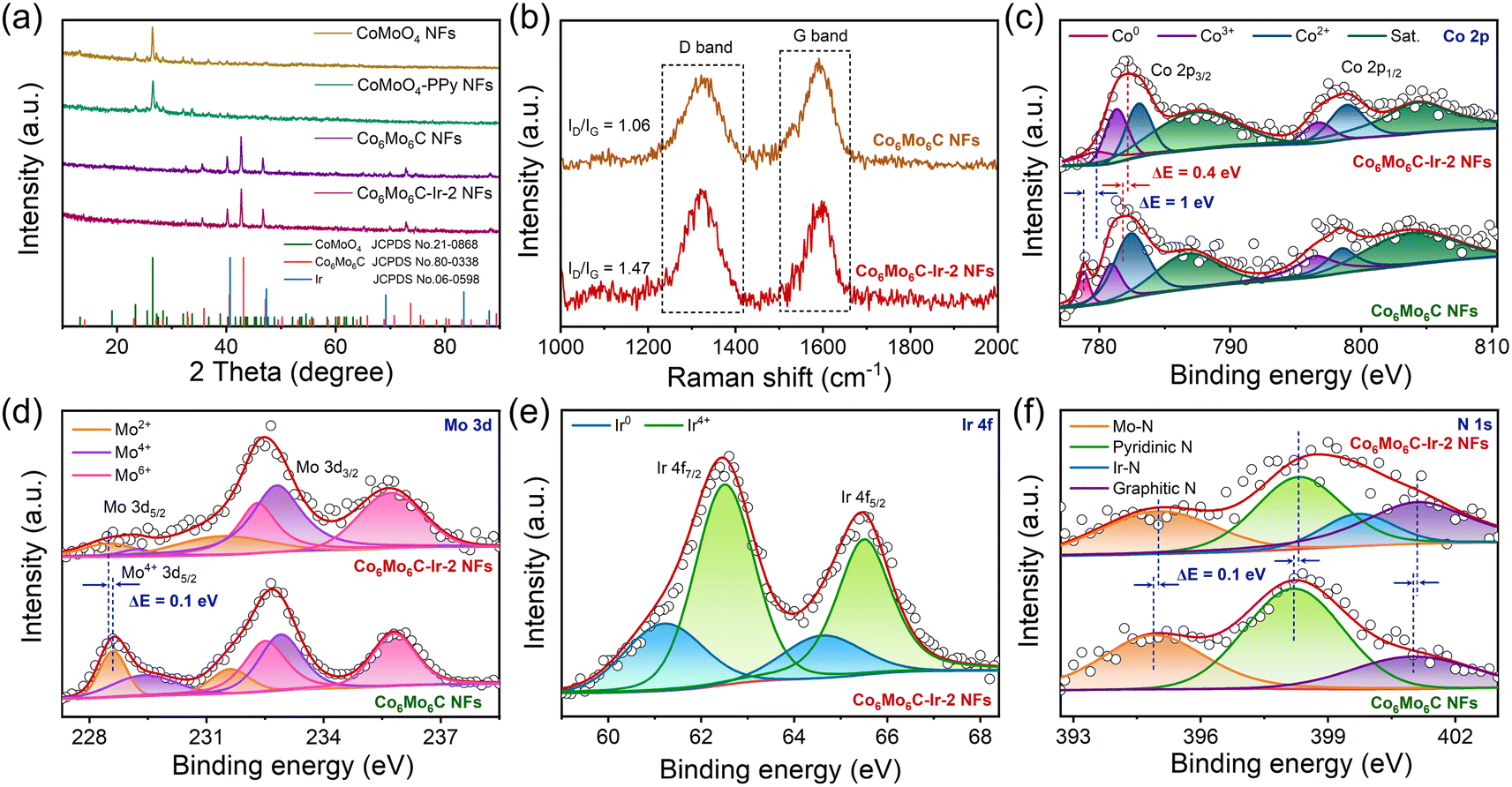 | ||
| Fig. 2 (a) XRD patterns of CoMoO4 NFs, CoMoO4-PPy NFs, Co6Mo6C NFs and Co6Mo6C-Ir-2 NFs. (b) Raman spectra of Co6Mo6C NFs and Co6Mo6C-Ir-2 NFs. (c) Typical high-resolution Co 2p XPS spectra of Co6Mo6C NFs and Co6Mo6C-Ir-2 NFs. (d) Typical high-resolution Mo 3d XPS spectra of Co6Mo6C NFs and Co6Mo6C-Ir-2 NFs. (e) Typical high-resolution Ir 4f XPS spectrum of Co6Mo6C-Ir-2 NFs. (f) Typical high-resolution N 1s XPS spectra of Co6Mo6C NFs and Co6Mo6C-Ir-2 NFs. | ||
X-ray photoelectron spectroscopy (XPS) analysis is implemented to further investigate the information pertaining to the surface composition and valence states. The XPS survey spectrum of Co6Mo6C-Ir-2 NFs not only illustrates the presence of Co, Mo, C and N elements but also yields the signal of Ir, corroborating the successful coverage of Ir nanoparticles (Fig. S11, ESI†). In the Co 2p XPS spectrum of Co6Mo6C NFs, the deconvoluted peak at 778.8 eV is assigned to the metallic Co0 species, while an additional six prominent peaks are ascribed to Co3+, Co2+ and their corresponding satellites, suggesting the formation of a Co6Mo6C structure (Fig. 2c).34,47,48 In addition, compared with Co6Mo6C NFs, the increase of the Co3+/Co2+ ratio in Co6Mo6C-Ir-2 NFs is attributed to the enhanced electron distribution for Co to donate electrons to adjacent atoms after the incorporation of Ir nanoparticles, which is confirmed by the following theoretical results. Moreover, the Mo 3d XPS spectra of Co6Mo6C NFs and Co6Mo6C-Ir-2 NFs can be deconvoluted into six peaks, featuring the Mo 3d5/2 and Mo 3d3/2 of Mo2+, which may contribute to the formation of a Mo–C bond, along with the Mo 3d5/2 and Mo 3d3/2 of Mo6+ and Mo4+ caused by the surface oxidation of Co6Mo6C (Fig. 2d).49–51 Notably, the variations of binding energies for both Co 2p and Mo 3d XPS of Co6Mo6C-Ir-2 NFs indicate that the integration of Ir may modulate the electronic structure of Co6Mo6C. With respect to the Ir 4f XPS spectrum of Co6Mo6C-Ir-2 NFs, the binding energies at 61.2 and 64.6 eV are assigned as the signals of metallic Ir0 4f7/2 and Ir0 4f5/2, respectively, indicating the successful generation of Ir nanoparticles in Co6Mo6C-Ir-2 NFs (Fig. 2e).22 The other two additional peaks are ascribed to Ir4+, which can be ascribed to the coordination between Ir atoms and adjacent atoms and slight inevitable surficial oxidation.22,52,53 Moreover, in the N 1s XPS spectrum of Co6Mo6C-Ir-2 NFs, the peaks at 395, 398.3, 399.7 and 401.1 eV can be variously assigned to Mo–N, pyridinic N (pN), Ir–N and graphitic N (gN), respectively, implying the formation of an N-doped carbon layer covering the surface of Co6Mo6C (Fig. 2f).54–56 Notably, in the N 1s XPS spectrum of Co6Mo6C NFs, all the peaks demonstrate a negative shift of 0.1 eV when compared to those of Co6Mo6C-Ir-2 NFs and the peak pertaining to Ir–N vanishes, revealing interfacial charge redistribution after the introduction of Ir nanoparticles. The produced pN and gN not only significantly improve the electrical conductivity but also modulate the band density of carbon through accepting electrons from neighboring carbon and metal atoms, which facilitates electron transfer and results in an enhanced electrocatalytic activity.56 The C 1s XPS spectra of Co6Mo6C NFs and Co6Mo6C-Ir-2 NFs are illustrated in Fig. S12 (ESI),† which can be fitted into four types of carbon species, i.e., metal–C (284.3 eV), C–C/C![[double bond, length as m-dash]](https://www.rsc.org/images/entities/char_e001.gif) C (284.9 eV), C–N/C–O (285.7 eV) and CO (286.5 eV).57,58
C (284.9 eV), C–N/C–O (285.7 eV) and CO (286.5 eV).57,58
2.2 Evaluation of OER performances
The electrocatalytic OER properties of different catalysts are examined in 1 M KOH solution, and electrochemical tests were executed in a three-electrode system. The corresponding electrocatalytic activities of CoMoO4 NFs with varying PPy contents following calcination are determined to illustrate the superior electrocatalytic performances of Co6Mo6C NFs (Fig. S13, ESI†). Polarization curves obtained at a scan rate of 1 mV s−1 are depicted in Fig. 3a. Among these catalysts, Co6Mo6C-Ir-2 NFs possess minimal overpotentials of 209 and 316 mV at 10 and 1000 mA cm−2, respectively, which are better than those of bare Co6Mo6C NFs, CoMoO4-PPy NFs and CoMoO4 NFs, and even far superior to those of IrO2 and Ir black (Fig. 3a and S14, ESI†). Moreover, the OER performance of Co6Mo6C-Ir-2 NFs also surpasses that of Co6Mo6C-Ir-1 NFs, Co6Mo6C-Ir-3 NFs, CoMoO4-50PPy-800-Ir NFs and CoMoO4-90PPy-800-Ir NFs (Fig. 3a and S15, ESI†). The decreased electrocatalytic performance of Co6Mo6C-Ir NFs with the further increase of anchoring Ir nanoparticles might be attributed to the agglomeration of active sites. In addition, Co6Mo6C-Ir-2 NFs show an excellent experimental reproducibility for the OER (Fig. S16, ESI†). Interestingly, Co6Mo6C-Ir-2 NFs also demonstrate markedly superior alkaline OER activity compared to other advanced OER electrocatalysts reported in the literature, particularly for a substantial current density of 1 A cm−2, which is feasible and valuable for industrial applications (Fig. 3b and Table S2, ESI†). Specifically, when compared with IrO2 and Ir black, Co6Mo6C-Ir-2 NFs exhibit a low Ir content but a considerably elevated current density at identical potentials (Fig. 3c), implying that limited quantities of Ir nanoparticles anchored on the surface of ultrathin carbon layer coated Co6Mo6C significantly reduce the cost of materials and achieve superior electrocatalytic performance. The normalization of the noble metal mass toward the current density is illustrated in Fig. 3d. Remarkably, Co6Mo6C-Ir-2 NFs show an extraordinarily large mass activity of 8895 A gNM−1 at an overpotential of 300 mV, approximately 774 and 523 times as high as that of IrO2 (11.5 A gNM−1) and Ir black (17 A gNM−1), respectively, suggesting their appealing commercial merit and feasibility for practical applications. Furthermore, Tafel slopes derived from linear sweep voltammetry (LSV) curves are employed to gain a deeper understanding of the reaction kinetics of catalysts. The Tafel slope of Co6Mo6C-Ir-2 NFs is 46.8 mV dec−1, which is lower than that of Co6Mo6C-Ir-1 NFs (53.3 mV dec−1), Co6Mo6C-Ir-3 NFs (67.1 mV dec−1), Co6Mo6C NFs (65.1 mV dec−1), CoMoO4-PPy NFs (84.1 mV dec−1) and CoMoO4 NFs (93.9 mV dec−1), and also notably superior to that of IrO2 (106.3 mV dec−1) and Ir black (68.2 mV dec−1), indicating the lower reaction barrier and accelerated reaction kinetics of Co6Mo6C-Ir-2 NFs toward the OER process (Fig. 3e).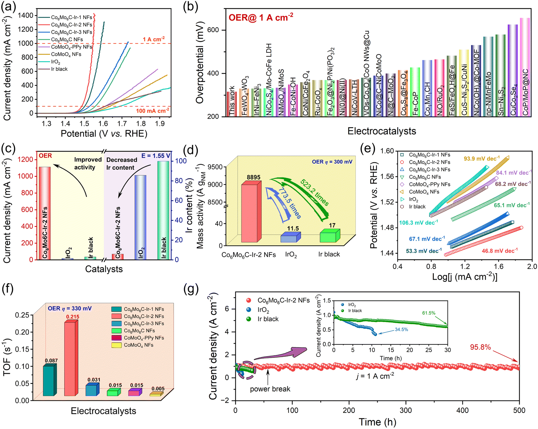 | ||
| Fig. 3 Electrochemical tests of Co6Mo6C-Ir-2 NFs and other catalysts for the OER in 1 M KOH solution. (a) The LSV curves at a scan rate of 1 mV s−1. (b) Comparison of overpotentials at a current density of 1 A cm−2 for various OER electrocatalysts. (c) Current densities at 1.55 V and Ir contents of catalysts. (d) The mass activities of noble metals for Co6Mo6C-Ir-2 NFs, IrO2 and Ir black. (e) Tafel plots of various catalysts. (f) The TOF values of Co6Mo6C-Ir-2 NFs and other catalysts. (g) The i–t curves of Co6Mo6C-Ir-2 NFs, IrO2 and Ir black at a current density of 1 A cm−2. | ||
Electrochemical impedance spectroscopy (EIS) of all the catalysts was performed to assess the electron transfer proficiency and electrochemical kinetics. The charge transfer resistance (Rct) value of Co6Mo6C-Ir-2 NFs is 1.22 Ω, which is lower than that of other catalysts, signifying their faster electron transfer capacity and enhanced kinetics due to interfacial electron redistribution (Fig. S17, ESI†). The double-layer capacitor (Cdl) values of catalysts are calculated from their cyclic voltammetry (CV) curves recorded in the non-Faraday region at various scan rates and are in proportion to the electrochemically active surface area (ECSA) values (Fig. S18, ESI†).59 As depicted in Fig. S19 (ESI),† Co6Mo6C-Ir-2 NFs exhibit a maximum Cdl value of 19.9 mF cm−2, compared with Co6Mo6C-Ir-1 NFs (9.3 mF cm−2), Co6Mo6C-Ir-3 NFs (8.3 mF cm−2) and Co6Mo6C NFs (1.1 mF cm−2). Moreover, Co6Mo6C-Ir-2 NFs possess the largest ECSA value of 44.78 cm2 and RF value of 497.5 amongst these catalysts (Table S3, ESI†), indicating an increase in the number of active sites after the incorporation of Ir species. Consequently, the ECSA-normalized LSVs are employed to gauge their intrinsic activity (Fig. S20, ESI†). Co6Mo6C-Ir-2 NFs show the lowest overpotential of 301 mV at 2.25 mA cmECSA−2, suggesting that Co6Mo6C-Ir-2 NFs not only provide an abundant number of active sites for electrocatalysis but also possess notable activity for each site toward the OER. These results indicate that an excessive amount of anchored Ir even exhibits a decreased ECSA, leading to a reduced intrinsic activity of the catalyst, which will be further discussed in the subsequent DFT calculation. Moreover, the turnover frequency (TOF) values of catalysts are also determined through ICP analysis (all the metals are deemed as active sites). As expected, the maximum TOF value of 0.215 s−1 for Co6Mo6C-Ir-2 NFs implies that Co6Mo6C-Ir-2 NFs have a relatively higher intrinsic activity (Fig. 3f). This superior intrinsic activity and larger ECSA are associated with the fact that the anchored Ir nanoparticles not only act as highly active sites for the OER but also facilitate interfacial electron redistribution to further optimize the adsorption of oxygen-containing intermediates.
To further evaluate their potential for practical application under industrial demands, robust stability is imperative for the catalyst. Therefore, numerous CV cycles are conducted to substantiate the outstanding stability of Co6Mo6C-Ir-2 NFs. Compared with the initial one, the LSV curve after 2000 CVs only shows a slight overpotential degradation at 1 A cm−2 (Fig. S21, ESI†). Moreover, at an industrial-level current density of 1 A cm−2, Co6Mo6C-Ir-2 NFs exhibit exceptional long-term stability following a continuous operation for roughly 500 h with a current density retention of 95.8% and a degradation rate of 0.08 mA cm−2 h−1 in alkaline medium, substantially outperforming those of IrO2 (34.5% after 11 h and 59.6 mA cm−2 h−1) and Ir black (61.5% after 30 h and 12.8 mA cm−2 h−1) (Fig. 3g and S22, ESI†). Incidentally, the structure of Co6Mo6C-Ir-2 NFs following an OER stability test is further investigated. The FESEM images of Co6Mo6C-Ir-2 NFs after the OER show no significant variance when compared with the initial morphology (Fig. S23, ESI†). The XRD examination after the OER can also discern the signals of Co6Mo6C, albeit with reduced peak intensity compared to before the OER (Fig. S24, ESI†). Raman spectra reveal that the ID/IG value of Co6Mo6C-Ir-2 NFs after the OER for 24 h (1.47) remains identical to its original state (Fig. S25, ESI†). After a 500 h OER test, the intensities of both the D band and G band become weaker yet still remain, owing to the partial dissolution of carbon during the long-term OER test. To evaluate the possible changes in the electronic structure and valence states, XPS characterization of Co6Mo6C-Ir-2 NFs after the OER is performed (Fig. S26 and S27, ESI†). Intriguingly, after the OER process, the increase of the intensity of Co3+ and Mox+ (x > 2) peaks and the generation of Ir3+ signify the partial superficial oxidation of Co6Mo6C-Ir-2 NFs (Fig. S26a–c, ESI†).60,61 In addition, the diminished intensity of the peaks for the N 1s XPS spectrum of Co6Mo6C-Ir-2 NFs after the OER slightly decreases, which might be caused by marginal dissolution of the coated ultrathin carbon layer, which is in accord with the above Raman results (Fig. S26d, ESI†). Furthermore, the almost unchanged C 1s XPS spectrum after the OER also confirms the retention of the carbon layer (Fig. S27, ESI†). These results convincingly confirm the exceptional stability of Co6Mo6C-Ir-2 NFs.
2.3 Evaluation of HER performances
In addition to the OER, Co6Mo6C-Ir-2 NFs exhibit exceptional HER performance in alkaline media, as demonstrated in Fig. 4 and S28 (ESI).† The overpotentials of Co6Mo6C NFs at 10 and 100 mA cm−2 are 266 and 380 mV. Following the anchoring with Ir nanoparticles, Co6Mo6C-Ir-2 NFs show the overpotentials of only 76 and 177 mV at 10 and 100 mA cm−2, which are only slightly inferior to those of Pt/C (48 and 134 mV at 10 and 100 mA cm−2) and Ir black (43 and 177 mV at 10 and 100 mA cm−2) at low current density (Fig. 4a). Furthermore, the Co6Mo6C-Ir-2 NFs exhibit a desirable experimental reproducibility for the HER (Fig. S29, ESI†). Meanwhile, to accommodate industrial demands for H2 production, the HER activity at large current density is also investigated. The surprising HER activity of Co6Mo6C-Ir-2 NFs with an overpotential of 348 mV at 1 A cm−2 surpasses that of Pt/C (354 mV at 1 A cm−2) and Ir black (520 mV at 500 mA cm−2), and even better than that of many state-of-the-art reported alkaline HER electrocatalysts (Fig. 4b and Table S4, ESI†). Moreover, regarding economic advantages and practical feasibility, the superior HER activity at ampere-level current density and less noble metal content of Co6Mo6C-Ir NFs would attract more attention (Fig. 4c). The HER activities of catalysts are also normalized by the mass of noble metal (Fig. 4d). The MANM value of Co6Mo6C-Ir-2 NFs is 9677 A gNM−1 at an overpotential of 300 mV, which is considerably higher than that of other commercial catalysts (3610 A gNM−1 for Pt/C and 190.3 A gNM−1 for Ir black), signifying the advantageous economical worth of Co6Mo6C-Ir-2 NFs for industrial applications. Moreover, Tafel plots are also obtained to investigate the HER mechanism of catalysts. The attained Tafel slope of Co6Mo6C-Ir-2 NFs (96.1 mV dec−1) is lower than that of Co6Mo6C-Ir-1 NFs (98.9 mV dec−1), Co6Mo6C-Ir-3 NFs (102.7 mV dec−1), Co6Mo6C NFs (104.5 mV dec−1), CoMoO4-PPy NFs (97.5 mV dec−1) and CoMoO4 NFs (120.6 mV dec−1), respectively, indicating that the exceptional kinetics of the HER process is consistent with the Volmer–Heyrovsky mechanism (Fig. 4e). Among these catalysts, Co6Mo6C-Ir-2 NFs also exhibit the lowest Rct value (4.66 Ω), signifying the significantly improved interfacial charge-transfer kinetics on the Co6Mo6C-Ir-2 NFs for the HER (Fig. S30, ESI†). As illustrated in Fig. S31 (ESI),† ECSA normalization is also performed to evaluate the intrinsic efficiency of catalysts and it is found that Co6Mo6C-Ir-2 NFs exhibit a low overpotential of 232 mV at a current density of 0.5 mA cmECSA−2, which is better than that of Co6Mo6C-Ir-1 NFs (327 mV) and Co6Mo6C-Ir-3 NFs (238 mV). The TOF values of each catalyst for the HER are also investigated (Fig. 4f). At an overpotential of 350 mV, the TOF values of Co6Mo6C-Ir-1 NFs, Co6Mo6C-Ir-2 NFs, Co6Mo6C-Ir-3 NFs, Co6Mo6C NFs, CoMoO4-PPy NFs and CoMoO4 NFs are 0.066, 0.391, 0.168, 0.022, 0.008 and 0.019 s−1, respectively, indicating that Co6Mo6C-Ir-2 NFs possess higher intrinsic activity besides a larger ECSA.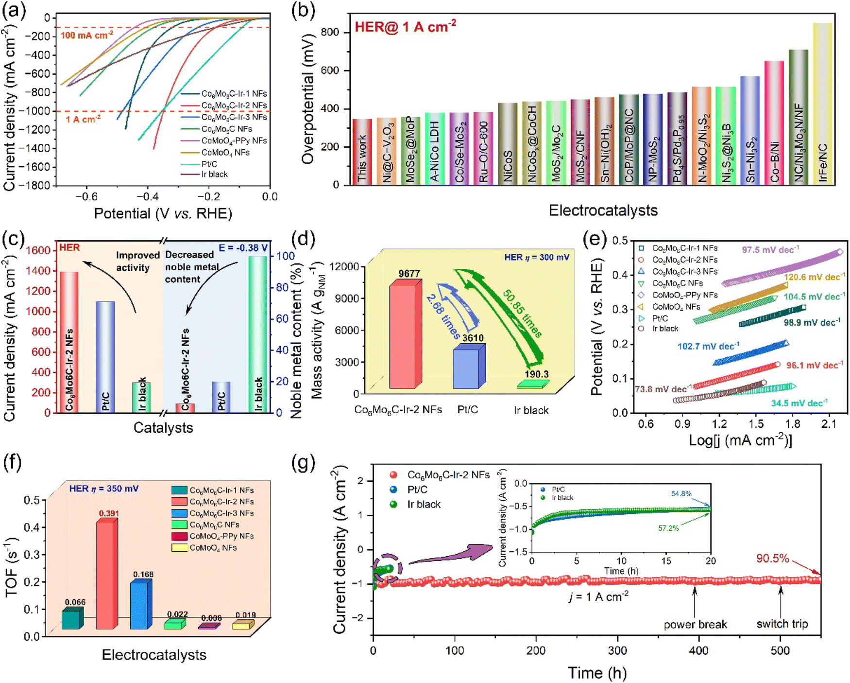 | ||
| Fig. 4 Electrochemical tests of Co6Mo6C-Ir-2 NFs and other catalysts for the HER in 1 M KOH solution. (a) The LSV curves at a scan rate of 1 mV s−1. (b) Comparison of overpotentials at a current density of 1 A cm−2 for various HER electrocatalysts. (c) Current densities at −0.38 V and noble metal contents of catalysts. (d) The mass activities based on noble metals for Co6Mo6C-Ir-2 NFs, IrO2 and Ir black. (e) Tafel plots for various catalysts. (f) The TOF values for Co6Mo6C-Ir-2 NFs and other catalysts. (g) The i–t curves of Co6Mo6C-Ir-2 NFs, Pt/C and Ir black at a current density of 1 A cm−2. | ||
Apart from examining the electrocatalytic activity, the durability of Co6Mo6C-Ir-2 NFs toward the HER is also assessed. At a large current density of 1 A cm−2, Co6Mo6C-Ir-2 NFs exhibit only 17 mV degradation after 2000 CVs and maintain 90.5% after 550 h with a minimal degradation rate of 0.17 mA cm−2 h−1, which significantly surpasses those of commercial Pt/C (54.8% for 20 h and 22.6 mA cm−2 h−1) and Ir black (57.2% for 20 h and 21.4 mA cm−2 h−1), suggesting the robust stability of Co6Mo6C-Ir-2 NFs for the HER in alkaline media with industrial level demands (Fig. 4g, S32 and S33, ESI†). The composition and structure of Co6Mo6C-Ir-2 NFs after a HER stability test are also discussed. Predictably, through a series of characterization techniques, including SEM, XRD, Raman, HRTEM and XPS, the morphology and structure of Co6Mo6C-Ir-2 NFs exhibit negligible changes after a prolonged HER stability test, demonstrating that Co6Mo6C-Ir-2 NFs show a wonderful structural and chemical stability toward the HER process (Fig. S34–S38, ESI†).
2.4 The investigations of the origins of high HER and OER catalytic activity
To gain an in-depth understanding of the high HER and OER catalytic activity of the newly obtained Co6Mo6C-Ir NF catalyst, density functional theory (DFT) calculations have been conducted based on the corresponding theoretical model (Fig. 5a, S39 and Table S5, ESI†). This model is configured by initially covering N-doped graphene with pN and gN on the low-index (100) surface of Co6Mo6C and subsequently depositing an Ir4 cluster on the surface of the carbon layer, as shown in Fig. 5a. Our computational results reveal that the Ir cluster can be stably anchored on the N-doped carbon layer, and three typical Ir atoms at the bottom can be connected by the pN atoms, the carbon atoms or the carbon atoms adjacent to the gN atoms, respectively. Based on this structural model, we first examined the HER catalytic activity of the Co6Mo6C-Ir NF system by assessing the ΔGH* values of potential catalytic sites. Additional details are provided in the ESI.† Ultimately, a multitude of H adsorption configurations can be established, encompassing the top sites of twelve C atoms (TC1–TC12), two N atoms (TpN and TgN) and four Ir atoms (TIr1–TIr4), along with some bridge (BIr1Ir2, BIr1Ir3 and BIr1Ir4) and hollow (HIr1Ir2Ir3, HIr1Ir2Ir4 and HIr1Ir3Ir4) sites on the Ir cluster, as illustrated in Fig. 5a. Our computed findings reveal that the relevant top, bridge and hollow sites on the Ir cluster can homogenously display small ΔGH* values in the range of −0.29–0.25 eV (Fig. 5b), and particularly some Ir-related bridge and hollow sites may even exhibit near-zero ΔGH* values, signifying considerable HER catalytic activity. Conversely, the TpN (0.73) and TgN (1.06 eV) sites possess negligible HER catalytic activity due to the relatively large ΔGH* value. Nonetheless, some carbon atoms close to the N atoms and Ir cluster can exhibit intense HER catalytic activity (Fig. 5b), including TC1 (0.14), TC2 (−0.25), TC3 (0.03), TC4 (−0.21), TC5 (0.13), TC6 (0.23) and TC7 (0.26 eV). In contrast, the carbon atoms (TC8–TC12 sites) far away from the doped N and the deposited Ir cluster will present relatively poor HER activity, due to their relatively large ΔGH* value (0.52–0.93 eV).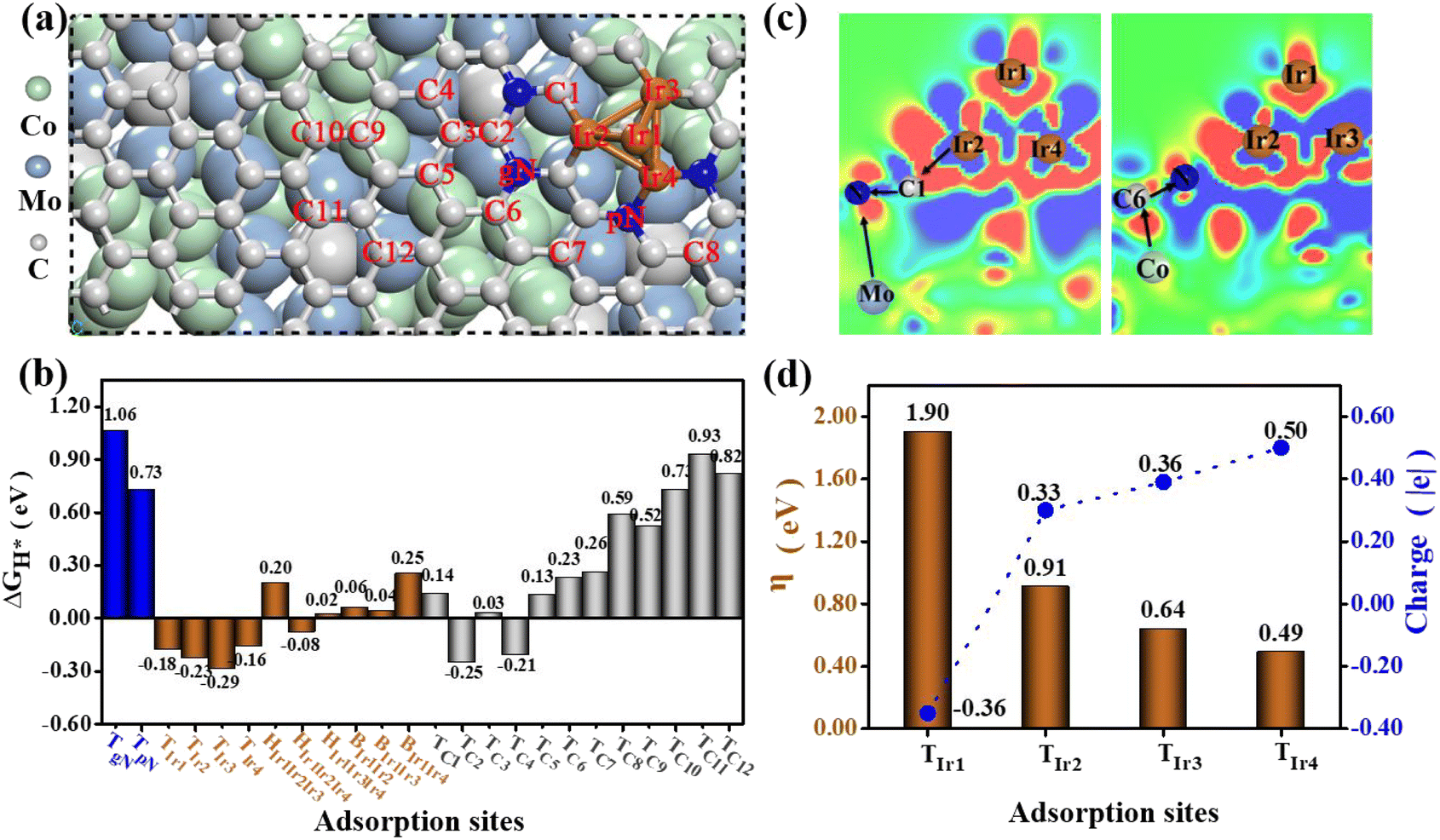 | ||
| Fig. 5 (a) The theoretical model used in DFT calculations and the obtained adsorption sites on the model surface; (b) the calculated free energies of H* adsorption (ΔGH*) for these adsorption sites; (c) the charge density difference (Δρ) of the composite Co6Mo6C-Ir NF system, in which the red and blue colors represent gaining and losing electrons, respectively, and the relevant electron transfer processes are displayed; (d) the overpotential η values of the OER on the surface of the composite Co6Mo6C-Ir NF system and the Bader charge of the corresponding active sites. | ||
Subsequently, we performed the computations of the charge density difference (Δρ) for the Co6Mo6C-Ir NF system. For comparison, Co6Mo6C-NFs without Ir are also considered. As illustrated in Fig. 5c and S40 (ESI),† unlike the case of Co6Mo6C-NFs without Ir, a range of complicated electron-transfer processes (e.g. Ir → C → N ← Mo and Co → C → N) are evident across Co6Mo6C-Ir NFs, wherein Ir and the corresponding Co/Mo atoms on both sides of the N-doped carbon layer act as electron donors, while N atoms can fulfill the role of electron acceptors. The synergistic effect of these complicated electron-transfer processes can substantially activate these relevant C and Ir atoms by finely modulating the electron density, thereby resulting in a superior HER activity in the catalytic system.
In the following, we have evaluated the OER catalytic activity of the Co6Mo6C-Ir NF system based on a relevant structural model by calculating the overpotential η value for all possible adsorption sites and ultimately identified four Ir-top sites (TIr1–TIr4), as illustrated in Fig. 5d. The detailed calculation processes of the overpotential η have been presented in Section 2.4 of the ESI.† Our computational analysis reveals that an excessive overpotential (1.90 V) may be encountered at the TIr1 site located at the top of the Ir-cluster, indicating diminished OER catalytic activity. This predominantly arises from the fact that the top Ir1 atom can only be connected with other adjacent metal Ir atoms instead of the nonmetal atoms with considerable electronegativity, inducing a relatively substantial electron density on it. This may be further supported by the Bader charge determination that the Ir1 atom can bear a negative charge of approximately −0.36|e| (Fig. 5d). The relatively considerable electron density will induce excessive adsorption of related O-containing species during the OER process (for instance, the reaction intermediate O* can even manifest a negative ΔGO* value of −0.30 eV (Fig. S41, ESI†)), leading to excessive overpotential and poor OER catalytic activity.
In comparison, the relevant Ir atoms (Ir2–Ir4) at the interface of the Co6Mo6C-Ir NF system can bond with the nonmetal N or C atoms, and the significant electron transfer from these Ir atoms to their adjacent N/C atoms can lower the electron density on them. The computed Bader charge results demonstrate that Ir2, Ir3 and Ir4 can bear positive the charges of 0.33, 0.36 and 0.50|e|, respectively (Fig. 5d). Consequently, this can diminish the adsorption strength of O* species at these Ir sites (Fig. S41, ESI†), improving the overpotential η value from 1.90 V to 0.49–0.91 V (Fig. 5d). Notably, the coordination of pN atoms can endow the corresponding Ir4 atom with the maximum OER catalytic ability (η = 0.49 V), considering the more pronounced reduction of electron density, leading to a more appropriate adsorption state of O*. It is noteworthy that the estimated η value of the Ir4 site (0.49 V) can even surpass that of the state-of-the-art IrO2 (0.56 V).62 Obviously, the coordination environment of Ir atoms in the catalyst system can significantly influence the OER catalytic performance, and the coordination of pN atoms can be deemed the most advantageous approach to attain an outstanding overpotential value. Hence, only the Ir atoms located at the interface exhibit excellent electrocatalytic activity and the excessive Ir sites with Ir–Ir bonds instead decrease the electrocatalytic activity of the catalyst.
2.5 Evaluation of OWS performances
In response to the exceptional electrocatalytic activity and durability of both the OER and the HER in alkaline media, an alkaline electrolyzer device for overall water splitting toward industrial applications is employed by Co6Mo6C-Ir-2 NFs as both the anode and the cathode. The polarization curves of the Co6Mo6C-Ir-2 NFs‖Co6Mo6C-Ir-2 NFs and Pt/C‖IrO2 electrolyzers are examined without iR compensation in 1 M KOH solution and are illustrated in Fig. 6a. Remarkably, the Co6Mo6C-Ir-2 NFs‖Co6Mo6C-Ir-2 NFs electrolyzer can deliver a low cell voltage of 1.5 V to reach 10 mA cm−2, which is much lower than that of the Pt/C‖IrO2 electrolyzer (1.62 V). This advantageous electrocatalytic activity enables the Co6Mo6C-Ir-2 NFs‖Co6Mo6C-Ir-2 NFs electrolyzer to be compared with other most recently reported alkaline electrolyzers (Fig. 6b and Table S6, ESI†). More astonishingly, to drive the current densities of 1 and 2 A cm−2, the Co6Mo6C-Ir-2 NFs‖Co6Mo6C-Ir-2 NFs electrolyzer needs only voltages of 2.79 and 3.87 V, respectively, outperforming the Pt/C‖IrO2 electrolyzer (4.27 V at 1 A cm−2). Meanwhile, the Faraday efficiencies (FEs) of the two electrolyzers under a current density of 200 mA cm−2 are also determined by using the drainage method to collect the produced H2 and O2 (Fig. S42 and S43, ESI†). The volumetric ratio of H2 and O2 captured by the Co6Mo6C-Ir-2 NFs‖Co6Mo6C-Ir-2 NFs electrolyzer approximates the predicted theoretical gas volume, and the achieved FEs are 97.6% and 99.0% for the HER and OER, respectively, surpassing those of the Pt/C‖IrO2 electrolyzer (92.4% and 53.2% for the HER and OER), highlighting the extraordinary applicability and promising potential of this assembled Co6Mo6C-Ir-2 NFs‖Co6Mo6C-Ir-2 NFs electrolyzer for energy storage and conversion (Fig. 6c, S44 and S45, ESI†). In addition, the ohmic overpotentials and activation overpotentials of both alkaline electrolyzers are investigated to mitigate the interference from solution resistance. As shown in Fig. 6d and e, compared with the Pt/C‖IrO2 electrolyzer, the Co6Mo6C-Ir-2 NFs‖Co6Mo6C-Ir-2 NFs electrolyzer presents a lower activation overpotential, corroborating the desirable energy efficiency of Co6Mo6C-Ir-2 NFs. Furthermore, the durability of both electrolyzers is evaluated at 1 A cm−2 (Fig. 6f). Interestingly, the Co6Mo6C-Ir-2 NFs‖Co6Mo6C-Ir-2 NFs electrolyzer can maintain 91.6% of its initial current density after 500 h with a degradation rate of 0.17 mA cm−2 h−1 and is better than the Pt/C‖IrO2 electrolyzer that only retains 38.6% of its initial current density after 25 h with a degradation rate of 24.6 mA cm−2 h−1, providing another confirmation of the exceptional stability of Co6Mo6C-Ir-2 NFs (Fig. S46, ESI†). The inset of Fig. 6f also depicts the instant generation of a dense bubble cloud composed of H2 and O2 gas, signaling the practicality and feasibility of Co6Mo6C-Ir-2 NFs for ampere-level alkaline water electrocatalysis. The Co6Mo6C-Ir-2 NFs‖Co6Mo6C-Ir-2 NFs cell is also tested under industrial conditions with concentrated KOH (30 wt%) at high temperature (60 and 80 °C).63,64 The assembled Co6Mo6C-Ir-2 NFs‖Co6Mo6C-Ir-2 NFs electrolyzer exhibits excellent overall water splitting performance at 1 A cm−2 in 30 wt% KOH at 60 °C (2.43 V) and 80 °C (2.40 V), which are better than those in 1 M KOH at room temperature (2.79 V), indicating the availability of Co6Mo6C-Ir-2 NFs for industrial applications (Fig. S47, ESI†).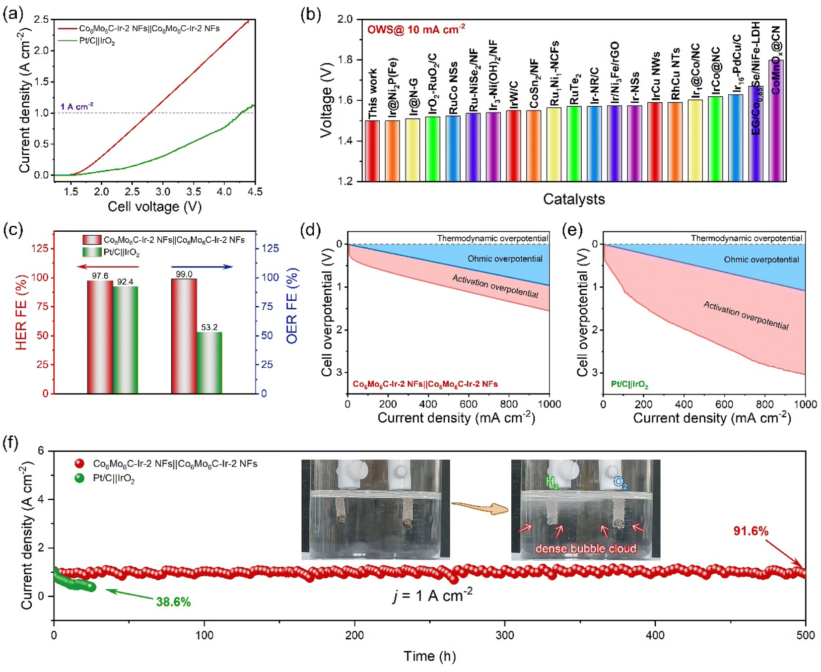 | ||
| Fig. 6 Electrochemical tests of Co6Mo6C-Ir-2 NFs‖Co6Mo6C-Ir-2 NFs and Pt/C‖IrO2 electrolyzers for OWS in 1 M KOH solution. (a) Polarization curves at a scan rate of 1 mV s−1 without iR compensation. (b) Comparison of overpotentials at a current density of 10 mA cm−2 in various OWS devices. (c) FEs at a current density of 200 mA cm−2. The calculations of the ohmic overpotential and activation overpotential for (d) Co6Mo6C-Ir-2 NFs‖Co6Mo6C-Ir-2 NFs and (e) Pt/C‖IrO2 electrolyzers. (f) The i–t curves of the two electrolyzers. Inset of (f): digital photograph of the Co6Mo6C-Ir-2 NFs‖Co6Mo6C-Ir-2 NFs electrolyzer loaded on nickel foam during the stability test with H2 and O2 evolution. | ||
3 Conclusion
In summary, we design a bifunctional electrocatalyst Co6Mo6C-Ir-2 NFs through a well-designed strategy involving the controllable fabrication of Co6Mo6C NFs and in situ growth of Ir nanoparticles. The synthesized Co6Mo6C-Ir-2 NFs demonstrate an enhanced electrocatalytic performance with the overpotentials of only 348 and 316 mV at 1 A cm−2 for the HER and OER, respectively, and both maintain stability for at least 500 h at ampere-level current density. Moreover, the assembled Co6Mo6C-Ir-2 NFs‖Co6Mo6C-Ir-2 NFs alkaline electrolyzer also exhibits a low cell voltage of 1.5 V at 10 mA cm−2 and maintained operational stability for over 500 h at 1 A cm−2. Based on structural characterization and DFT calculations, their remarkable electrocatalytic performance can be attributed to the following aspects: (1) the introduction of Ir nanoparticles not only provide rich active sites but also induce an intense interface effect between Co6Mo6C and the N-doped carbon layer to activate adjacent inactive C atoms, thereby exhibiting high HER catalytic activity with nearly zero ΔGH* values; (2) the integration of Ir atoms with neighboring N/C atoms can induce an efficacious electron transfer to alleviate the enrichment of the electron density of Ir atoms, which can weaken and attain the appropriate adsorption strength of O* species at Ir sites, thereby resulting in superior OER catalytic performance; (3) the high electrical conductivity, large ECSA and various pathways for electron-transfer processes that are induced by the enhanced charge redistribution after introducing Ir nanoparticles make a great contribution to the enhancement of their electrocatalytic performance. As such, our research illuminates and offers significant guidance for the rational design of low-Ir-loading materials with outstanding activity and durability as advanced alkaline bifunctional electrocatalysts for industrial applications.Data availability
Data supporting the findings of this study are available within the article ESI.†Author contributions
W. Li and W. Gou contributed equally to this work. X. Lu and C. Wang conceived the experiments and supervised this project. W. Li performed the experiments. W. Li, L. Zhang, S. Ren, and M. Zhong characterized the catalysts and analyzed the data. W. Gou, G. Yu and W. Chen carried out the theoretical calculation. W. Li and W. Gou wrote the manuscript. All authors have approved the final version of the manuscript.Conflicts of interest
The authors declare no conflict of interest.Acknowledgements
This work was financially supported by the National Natural Science Foundation of China (52273056), the Natural Science Foundation of Fujian Province (2022J01167), Research Foundation of Academy of Carbon Neutrality of Fujian Normal University (TZH2022-05), Minjiang Scholar and startup fund for high-level talent at Fujian Normal University, and Fujian-Taiwan Science and Technology Cooperation Base of Biomedical Materials and Tissue Engineering (2021D039). We acknowledge the Computing Center of Jilin Province for supercomputer time.References
- Z. W. Seh, J. Kibsgaard, C. F. Dickens, I. B. Chorkendorff, J. K. Norskov and T. F. Jaramillo, Science, 2017, 355, eaad4998 CrossRef PubMed.
- M. Chatenet, B. G. Pollet, D. R. Dekel, F. Dionigi, J. Deseure, P. Millet, R. D. Braatz, M. Z. Bazant, M. Eikerling, I. Staffell, P. Balcombe, Y. Shao-Horn and H. Schafer, Chem. Soc. Rev., 2022, 51, 4583 RSC.
- J. A. Turner, Science, 2004, 305, 972 CrossRef CAS PubMed.
- D. G. Li, E. J. Park, W. L. Zhu, Q. R. Shi, Y. Zhou, H. Y. Tian, Y. H. Lin, A. Serov, B. Zulevi, E. D. Baca, C. Fujimoto, H. T. Chung and Y. S. Kim, Nat. Energy, 2020, 5, 378 CrossRef CAS.
- Z.-Y. Yu, Y. Duan, X.-Y. Feng, X. X. Yu, M.-R. Gao and S.-H. Yu, Adv. Mater., 2021, 33, 2007100 CrossRef CAS PubMed.
- X. X. Yu, Z.-Y. Yu, X.-L. Zhang, Y.-R. Zheng, Y. Duan, Q. Gao, R. Wu, B. Sun, M.-R. Gao, G. X. Wang and S.-H. Yu, J. Am. Chem. Soc., 2019, 141, 7537 CrossRef CAS PubMed.
- S. P. Zeng, H. Shi, T. Y. Dai, Y. Liu, Z. Wen, G. F. Han, T. H. Wang, W. Zhang, X. Y. Lang, W. T. Zheng and Q. Jiang, Nat. Commun., 2023, 14, 1811 CrossRef CAS PubMed.
- W. M. Li, R. Liu, G. T. Yu, X. J. Chen, S. Yan, S. Y. Ren, J. J. Chen, W. Chen, C. Wang and X. F. Lu, Small, 2023, 2307164 Search PubMed.
- X. Y. Chen, J. W. Wan, J. Wang, Q. H. Zhang, L. Gu, L. R. Zheng, N. Wang and R. B. Yu, Adv. Mater., 2021, 33, 2104764 CrossRef CAS PubMed.
- T. Wu, E. H. Song, S. N. Zhang, M. J. Luo, C. D. Zhao, W. Zhao, J. J. Liu and F. Q. Huang, Adv. Mater., 2022, 34, 2108505 CrossRef CAS PubMed.
- W. M. Li, C. Wang and X. F. Lu, Coord. Chem. Rev., 2022, 464, 214555 CrossRef CAS.
- M. X. Zhong, J. Y. Yang, M. J. Xu, S. Y. Ren, X. J. Chen, C. Wang, M. B. Gao and X. F. Lu, Small, 2023, 2304782 Search PubMed.
- Z. H. Pu, J. H. Zhao, I. S. Amiinu, W. Q. Li, M. Wang, D. P. He and S. C. Mu, Energy Environ. Sci., 2019, 12, 952–957 RSC.
- D. Chen, Z. H. Pu, P. Y. Wang, R. H. Lu, W. H. Zeng, D. L. Wu, Y. T. Yao, J. W. Zhu, J. Yu, P. X. Ji and S. C. Mu, ACS Catal., 2022, 12, 2623–2631 CrossRef CAS.
- W. L. Zhao, F. H. Xu, L. Q. Liu, M. Liu and B. C. Weng, Adv. Mater., 2023, 2308060 CrossRef CAS PubMed.
- Y. B. Wang, R. P. Ma, Z. P. Shi, H. X. Wu, S. Hou, Y. Wang, C. P. Liu, J. J. Ge and W. Xing, Chem, 2023, 9, 2931 CAS.
- Z. P. Shi, J. Li, J. D. Jiang, Y. B. Wang, X. Wang, Y. Li, L. T. Yang, Y. Y. Chu, J. S. Bai, J. H. Yang, J. Ni, Y. Wang, L. J. Zhang, Z. Jiang, C. P. Liu, J. J. Ge and W. Xing, Angew. Chem., Int. Ed., 2022, 61, e202212341 CrossRef CAS PubMed.
- Y. F. Wang, P. Han, X. M. Lv, L. J. Zhang and G. F. Zheng, Joule, 2018, 2, 2551 CrossRef CAS.
- J. W. Nai, X. Z. Xu, Q. F. Xie, G. X. Lu, Y. Wang, D. Y. Luan, X. Y. Tao and X. W. Lou, Adv. Mater., 2021, 34, 2104405 CrossRef PubMed.
- J. W. Zhu, Y. Guo, F. Liu, H. W. Xu, L. Gong, W. J. Shi, D. Chen, P. Y. Wang, Y. Yang, C. T. Zhang, J. S. Wu, J. H. Luo and S. C. Mu, Angew. Chem., Int. Ed., 2021, 60, 12328 CrossRef CAS PubMed.
- T. Wang, Y. T. Zeng, M. Y. Xu, J. Zhang, S. Y. Wu, S. C. Mu and J. Yu, Langmuir, 2023, 39, 4005–4014 CrossRef CAS PubMed.
- J. Yang, Y. Shen, Y. M. Sun, J. H. Xian, Y. J. Long and G. Q. Li, Angew. Chem., Int. Ed., 2023, 62, e202302220 CrossRef CAS PubMed.
- D. Tian, S. R. Denny, K. Z. Li, H. Wang, S. Kattel and J. G. Chen, Chem. Soc. Rev., 2021, 50, 12338 RSC.
- K. Kawashima, R. A. Marquez, L. A. Smith, R. R. Vaidyula, O. A. Carrasco-Jaim, Z. Q. Wang, Y. J. Son, C. L. Cao and C. B. Mullins, Chem. Rev., 2023, 123, 12795–13208 CrossRef CAS PubMed.
- Q. S. Gao, W. B. Zhang, Z. P. Shi, L. C. Yang and Y. Tang, Adv. Mater., 2019, 31, 1802880 CrossRef PubMed.
- M. Feng, J. L. Huang, Y. Peng, C. R. Huang, X. Yue and S. M. Huang, ACS Nano, 2022, 16, 13834 CrossRef CAS PubMed.
- X. B. Bao, T. Wang and Y. Yang, Mater. Chem. Front., 2024, 8, 627–651 RSC.
- X. Z. Zheng, Y. Z. Chen, X. B. Bao, S. J. Mao, R. X. Fan and Y. Wang, ACS Catal., 2020, 10, 11634 CrossRef CAS.
- M. Y. Zu, P. F. Liu, C. W. Wang, Y. Wang, L. R. Zheng, B. Zhang, H. J. Zhao and H. G. Yang, ACS Energy Lett., 2018, 3, 78 CrossRef CAS.
- Z. M. Cui, Y. T. Li, G. T. Fu, X. Li and J. B. Goodenough, Adv. Mater., 2017, 29, 1702385 CrossRef PubMed.
- J. G. Hou, Y. Z. Wu, S. Y. Cao, Y. Q. Sun and L. C. Sun, Small, 2017, 13, 1702018 CrossRef PubMed.
- X. L. Lin, J. L. Liu, X. Q. Qiu, B. W. Liu, X. F. Wang, L. H. Chen and Y. L. Qin, Angew. Chem., Int. Ed., 2023, 62, e202306333 CrossRef CAS PubMed.
- J. W. Li, Y. Z. Hu, X. Huang, Y. Zhu and D. L. Wang, Small, 2023, 19, 2206533 CrossRef CAS PubMed.
- C. Y. He and J. Z. Tao, J. Catal., 2017, 347, 63 CrossRef CAS.
- S. Geng, S. C. Xu, Y. S. Yu, W. W. Yang, M. Feng and H. B. Li, J. Electroanal. Chem., 2020, 871, 114271 CrossRef CAS.
- G. Y. Shi, T. Tano, D. A. Tryk, T. Uchiyama, A. liyama, M. Uchida, K. Terao, M. Yamaguchi, K. Tamoto, Y. Uchimoto and K. Kakinuma, ACS Catal., 2023, 13, 12299 CrossRef CAS.
- R.-Q. Yao, H. Shi, W.-B. Wan, Z. Wen, X.-Y. Lang and Q. Jiang, Adv. Mater., 2020, 32, 1907214 CrossRef CAS PubMed.
- X. W. Yu, R. B. Araujo, Z. Qiu, E. C. Dos Santos, A. Anil, A. Cornell, L. G. M. Pettersson and M. Johnsson, Adv. Energy Mater., 2022, 12, 2103750 CrossRef CAS.
- C. Li, W. Zhang, Y. Y. Cao, J.-Y. Ji, Z.-C. Li, X. Han, H. W. Gu, P. Braunstein and J.-P. Lang, Adv. Sci., 2024, 2401780 CrossRef PubMed.
- Y. X. Weng, K. Y. Wang, S. Y. Li, Y. X. Wang, L. F. Lei, L. Z. Zhuang and Z. Xu, Adv. Sci., 2023, 10, 2205920 CrossRef CAS PubMed.
- J. M. Yu, J. Song, Y. K. Kim, J. Oh, K. Y. Kim, W. Y. Noh, W. J. Byun, J. U. Lee, C. Yang, J. W. Jang, J. S. Lee and S. Cho, Nano Lett., 2023, 23, 5092–5100 CrossRef CAS PubMed.
- W. Peng, Y. Wang, X. X. Yang, L. C. Mao, J. H. Jin, S. L. Yang, K. Fu and G. Li, Appl. Catal., B, 2020, 268, 118437 CrossRef CAS.
- W. Y. Ding, A. Saad, Y. C. Wu, Z. W. Wang and X. T. Li, Nano Res., 2023, 16, 4793–4802 CrossRef CAS.
- Q. C. Wang, Y. Tan, S. H. Tang, W. Liu, Y. Zhang, X. Xiong and Y. P. Lei, ACS Nano, 2023, 17, 9565 CrossRef CAS PubMed.
- Y. M. Peng, Y. W. Zhang, A. Guo, M. Y. Mao, Y. Wang, Y. Long and G. Y. Fan, Chem. Eng. J., 2022, 433, 133648 CrossRef CAS.
- D. Yue, T. L. Feng, Z. C. Zhu, S. Y. Lu and B. Yang, ACS Catal., 2024, 14, 3006–3017 CrossRef CAS.
- Q. Wang, H. Xu, X. Y. Qian, G. Y. He and H. Q. Chen, Appl. Catal., B, 2022, 322, 122104 CrossRef.
- Y. K. Lu, X. Y. Zheng, Y. Liu, J. J. Zhu, D. Li and D. L. Jiang, Inorg. Chem., 2022, 61, 8328 CrossRef CAS PubMed.
- Y. C. Wan, Z. J. Wang, J. Li and R. T. Lv, ACS Nano, 2021, 16, 643 CrossRef PubMed.
- M. X. Li, Y. Zhu, H. Y. Wang, C. Wang, N. Pinna and X. F. Lu, Adv. Energy Mater., 2019, 9, 1803185 CrossRef.
- F. F. Peng, L. H. Zhang, B. Jiang, H. Z. Dou, M. Xu, N. Yang, J. Z. Zhang and Y. L. Sun, Chem. Eng. J., 2021, 427, 131712 CrossRef.
- J. Yin, J. Jin, M. Lu, B. L. Huang, H. Zhang, Y. Peng, P. X. Xi and C.-H. Yan, J. Am. Chem. Soc., 2020, 142, 18378–18386 CrossRef CAS PubMed.
- Z. Q. Dong, C. H. Zhou, W. B. Chen, F. X. Lin, H. Luo, Z. Q. Sun, Q. Z. Huang, R. J. Zeng, Y. J. Tan, Z. H. Xiao, H. S. Huang, K. Wang, M. C. Luo, F. Lv and S. J. Guo, Adv. Funct. Mater., 2024, 2400809 CrossRef.
- X. J. Wu, B. M. Feng, W. Li, Y. L. Niu, Y. A. Yu, S. Y. Lu, C. Y. Zhong, P. Y. Liu, Z. Q. Tian, L. Chen, W. H. Hu and C. M. Li, Nano energy, 2019, 62, 117 CrossRef CAS.
- Z. P. Yu, C. W. Si, A. P. LaGrow, Z. X. Tai, W. A. Caliebe, A. Tayal, M. J. Sampaio, J. P. S. Sousa, I. Amorim, A. Araujo, L. J. Meng, J. L. Faria, J. Y. Xu, B. Li and L. F. Liu, ACS Catal., 2022, 12, 9397 CrossRef CAS.
- F. F. Peng, L. H. Zhang, B. Jiang, H. Z. Dou, M. Xu, N. Yang, J. Z. Zhang and Y. L. Sun, Chem. Eng. J., 2022, 427, 131712 CrossRef CAS.
- T. Y. Gong, J. Y. Zhang, Y. Liu, L. R. Hou, J. L. Deng and C. Z. Yuan, Chem. Eng. J., 2023, 451, 139025 CrossRef CAS.
- S. X. Yang, R. Q. Du, Y. H. Yu, Z. P. Zhang and F. Wang, Nano Energy, 2020, 77, 105057 CrossRef CAS.
- C. Y. Li, Z. J. Wang, M. D. Liu, E. Z. Wang, B. L. Wang, L. L. Xu, K. L. Jiang, S. S. Fan, Y. H. Sun, J. Li and K. Liu, Nat. Commun., 2022, 13, 3338 CrossRef PubMed.
- W. B. Chen, Y. X. Xie, X. H. Gao, L. Li and Z. Lin, J. Mater. Chem. A, 2022, 10, 15543 RSC.
- T. Y. Gong, J. Y. Zhang, Y. Liu, L. R. Hou, J. L. Deng and C. Z. Yuan, Chem. Eng. J., 2023, 451, 139025 CrossRef CAS.
- J. Rossmeisl, Z. W. Qu, H. Zhu, G. J. Kroes and J. K. Norskov, J. Electroanal. Chem., 2007, 607, 83 CrossRef CAS.
- M. Q. Yu, E. Budiyanto and H. Tuysuz, Angew. Chem., Int. Ed., 2022, 61, e202103824 CrossRef CAS PubMed.
- N. Chen, S. Y. Paek, J. Y. Lee, J. H. Park, S. Y. Lee and Y. M. Lee, Energy Environ. Sci., 2021, 14, 6338–6348 RSC.
Footnotes |
| † Electronic supplementary information (ESI) available. See DOI: https://doi.org/10.1039/d4sc02840f |
| ‡ These authors contributed equally to this work. |
| This journal is © The Royal Society of Chemistry 2024 |