
 Open Access Article
 This Open Access Article is licensed under a Creative Commons Attribution-Non Commercial 3.0 Unported Licence
Monolithic 3D nanoelectrospray emitters based on a continuous fluid-assisted etching strategy for glass droplet microfluidic chip-mass spectrometry†
Ziyang
Guo
a,
Yingqi
Zhao
a,
Zhao
Jin
a,
Yaran
Chang
a,
Xiayan
Wang
 a,
Guangsheng
Guo
ab and
Yaoyao
Zhao
*a
a,
Guangsheng
Guo
ab and
Yaoyao
Zhao
*a
aDepartment of Chemistry, Beijing University of Technology, Beijing, 100124, China. E-mail: zhaoyaoyao@bjut.edu.cn
bMinzu University of China, Beijing, 100081, China
First published on 23rd April 2024
Abstract
Glass microfluidic chips are suitable for coupling with mass spectrometry (MS) due to their flexible design, optical transparency and resistance to organic reagents. However, due to the high hardness and brittleness of glass, there is a lack of simple and feasible technology to manufacture a monolithic nanospray ionization (nESI) emitter on a glass microchip, which hinders its coupling with mass spectrometry. Here, a continuous fluid-assisted etching strategy is proposed to fabricate monolithic three-dimensional (3D) nESI emitters integrated into glass microchips. A continuous fluid of methanol is adopted to protect the inner wall of the channels and the bonding interface of the glass microfluidic chip from being wet-etched, forming sharp 3D nESI emitters. The fabricated 3D nESI emitter can form a stable electrospray plume, resulting in consistent nESI detection of acetylcholine with an RSD of 4.5% within 10 min. The fabricated 3D emitter is integrated on a glass microfluidic chip designed with a T-junction droplet generator, which can realize efficient analysis of acetylcholine in picoliter-volume droplets by nESI-MS. Stability testing of over 20![[thin space (1/6-em)]](https://www.rsc.org/images/entities/char_2009.gif) 000 droplets detected by the established system resulted in an RSD of 9.1% over approximately 180 min. The detection of ten neurochemicals in rat cerebrospinal fluid droplets is achieved. The established glass droplet microfluidic chip-MS system exhibits potential for broad applications such as in vivo neurochemical monitoring and single-cell analysis in the future.
000 droplets detected by the established system resulted in an RSD of 9.1% over approximately 180 min. The detection of ten neurochemicals in rat cerebrospinal fluid droplets is achieved. The established glass droplet microfluidic chip-MS system exhibits potential for broad applications such as in vivo neurochemical monitoring and single-cell analysis in the future.
Introduction
Microfluidic devices have shown pronounced advantages in the automated high-throughput analysis of small-volume samples and have been widely utilized in bioanalytical research and applications.1–3 The flexible design of the microchip structure allows the integration of various detection approaches on the microfluidic platform.4–7 There has been great progress in the coupling of microfluidic devices to mass spectrometry (MS), which has high sensitivity and rapid response, is label-free, and can provide rich structural information.8,9 Among them, nanoelectrospray ionization mass spectrometry (nESI-MS) has gained continuous attention in recent years due to its low sample consumption, good matrix tolerance, and no need for a sheath gas.10 Moreover, the ideal flow rates of nESI-MS can match that of microfluidic devices.11 The fluids flowing out from the microchannel outlet of the microfluidic device could be directly ionized, and continuously detected by MS in real-time. The chip-nESI-MS technique has been successfully used to couple various microfluidic devices to MS, such as chip electrophoresis,12–14 chip chromatography,15–18 and droplet microfluidics.19,20Droplet microfluidics is a technique for femtoliter to microliter samples to be encapsulated by immiscible carrier phases.3,21,22 The coupling of droplet microfluidics and nESI-MS has emerged as a powerful tool used for high-throughput analysis in multidisciplinary research fields.11 Various materials, including polydimethylsiloxane (PDMS), silicon and glass, have been used to fabricate droplet microfluidic chips.23–25 PDMS is the most widely used because of its easy fabrication, light transmittance and good biocompatibility, but its inherent drawbacks, such as low mechanical strength and intolerance to organic solvents,26 may affect the stability of droplet generation and the introduction of redundant impurity peaks during MS detection, respectively. Compared to silicon substrates, glass-based droplet microfluidic chips are more suitable for droplet characterization prior to MS detection due to the optical transparency.
The crucial point of the online coupling of microfluidic devices with nESI-MS is the interface, which is related to the ionization efficiency during MS detection. According to the principle of nESI, a sharp emitter would reduce the diffusion of the sample at the channel outlet and facilitate the generation of small Taylor cones that are essential for efficient ionization.27,28 Glass capillary emitters or stainless steel emitters were usually integrated into the fluid outlet channel of the PDMS device.29,30 Due to the deformable characteristics of PDMS, the dead volume at the connection between the external emitter and the microfluidic chip channel can be avoided. Kempa et al. incorporated stainless steel emitters into the fluid outlet channel of PDMS devices and secured them using silicone sealant.29 It was discovered that the Orbitrap platform could only detect droplet signals within 6 Hz, while the TWIMS Q-TOF could obtain mass spectrometry information from droplets at 33 Hz. Zhang et al. combined a silicon-based droplet microfluidic chip with MS detection to prepare an integrated emitter through ICP-RIE etching and DRIE etching.11 However, this standard emitter fabrication method is only suitable for silicon-based materials and cannot be applied to other materials. Monolithic integration of an nESI emitter on a glass microfluidic chip has obvious advantages over external emitters with negligible dead volume and ease of tricky assembly procedures.31–33
Ramsey's group fabricated a two-dimensional (2D) nESI emitter by sawing a sharp corner at the end of a microchannel of an extremely thin (300 μm) glass chip.34–36 However, the fabrication of such 2D emitters relies on rather harsh mechanical machining and the extremely thin glass wafers that are required to generate electrospray are difficult to handle.31 Building 3D emitters on borosilicate glass chips of standard thickness is an ideal alternative approach, which facilitates the fabrication of sharper emitters to form smaller Taylor cones. Fang's group manually ground the tip of a glass chip into a pyramid shape as an nESI emitter.32 Sainiemi et al. fabricated a 3D sharp nESI emitter through anisotropic isotropic etching of two glass wafers,31 eliminating manual processing steps. Belder's group described methods for monolithically integrated nESI emitters in glass chips, including drawing and then etching to fabricate nESI emitters,33,37 and rough sawing, grinding, and hydrophobic treatments to prepare nESI emitters,38 which have been successfully applied to MS coupling for on-chip electrophoresis39–41 and on-chip reaction monitoring.42 In the current strategies for preparing emitters related to etching technology, the strategy of etching before bonding involves etching of two glass wafers, which increases the difficulty of glass chip bonding; the strategy of etching after bonding requires computer numerical control (CNC) milling, which is expensive and not easily accessible; the strategy of sawing, grinding, and hydrophobic treatments, which is difficult to guarantee repeatability. Therefore, there is an urgent need to develop simple and versatile etching methods for monolithically integrated nESI emitters, which can be used to facilitate the development of coupling strategies for glass microfluidic chips and MS. However, fabrication of monolithically integrated nESI emitters on glass microfluidic chips through an etching technique still remains a challenge due to the interfacial voids that exist at the bonding interface of glass chips.43
In this study, we proposed a simple and effective continuous fluid-assisted etching strategy to fabricate monolithically integrated 3D nESI emitters (Fig. 1A). Unlike previous manual grinding techniques, this method uses a standard etching process, which allows the mass production of integrated glass microchips with sharp 3D nESI emitters. A glass micro-fluidic system was designed to integrate a T-junction droplet generator and an etched 3D nESI emitter to efficiently analyze neurochemicals in picoliter level volume of aqueous droplets in oil by nESI-MS (Fig. 1B). Due to the optical transparency of the glass, the droplet could be optically tracked by the microscope equipped in front of the mass spectrometer. In addition, the good mechanical strength of the glass ensures the stability of the generated droplets and the reusability of the microfluidic chip. The developed system was successfully applied to the detection of neurochemicals in rat cerebrospinal fluid droplets.
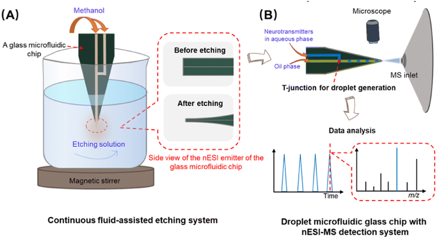 | ||
| Fig. 1 (A) Schematic diagram of a continuous fluid-assisted etching system for fabricating the microfluidic glass chip with a monolithically integrated 3D nESI emitter. (B) Droplet microfluidic glass chip based on a T-junction with the nESI-MS detection system. | ||
Results and discussion
Fabrication of nESI emitters monolithically integrated on glass microfluidic chips
Due to the high hardness and brittleness characteristics of glass, producing a sharp emitter on a glass chip is still a challenging issue. In this work, we proposed a simple, controllable, and reliable continuous fluid-assisted etching strategy to fabricate monolithically integrated 3D nESI emitters after the glass chip bonding. Firstly, prior to wet etching, the exit of the chip microchannel was cut into a sharp angle (30°) to form a 2D emitter (Fig. S1†). A wet etching method with HF was used to fabricate nESI emitters. In order to protect the interior of the glass microfluidic channel from etching, a continuous fluid of methanol was adopted to prevent the enlargement of the channel's inner diameter. In addition, a magnetic stirrer was used to maintain the homogeneity of the etching solution, which was the key to preparing integrated nESI emitters with high reproducibility. The schematic diagram of the continuous fluid-assisted wet etching system is shown in Fig. 1A and the photograph is shown in Fig. S2.†To demonstrate the role of the continuous fluid of methanol during the etching process on 3D nESI emitters, the etching performance of the emitters was compared with or without the continuous fluid of methanol (Fig. 2). Compared with the emitter before etching (Fig. 2A), the thickness of the emitter can be effectively reduced by the wet etching method for 15 min (Fig. 2B and C). As shown in Fig. 2C-2, the continuous fluid in the channel could protect the interior of the glass microfluidic channel from etching. Without continuous fluid, capillary action caused the etching solution to enter the channels of the glass chip, resulting in the etching step of the channel walls and the enlargement of the inner diameter at the tip (Fig. 2B-2). The photomicrograph of the nESI emitters etched for 5 min (Fig. S3†) further confirmed the role of continuous fluid, avoiding the etching of channels due to capillary action. In addition, without continuous fluid protection, the etching rate of the bonding interface of glass chips was faster than that of other glass integral parts, where the two glass layers had been partially separated at the tip (Fig. 2B-2 and B-3), which was due to the existence of interfacial voids at the bonding interface. However, when using the continuous fluid, there was no obvious etching at the bonding interface (Fig. 2C-2 and C-3). This result demonstrates that the continuous fluid not only protects the interior of the channel of glass microfluidic chips, but also protects the bonding interface from etching.
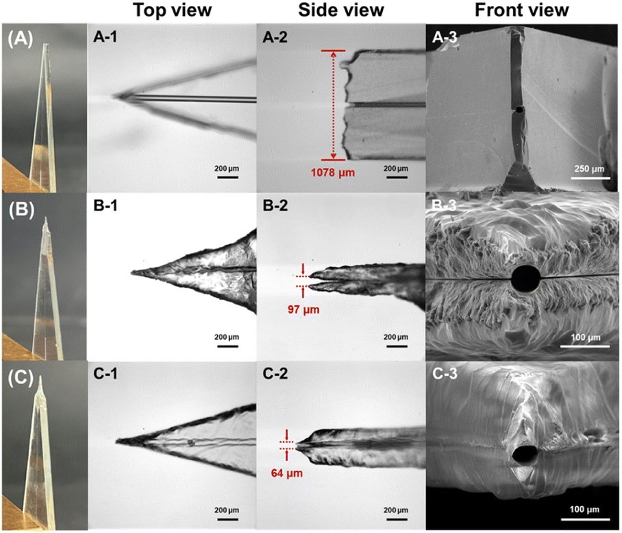 | ||
| Fig. 2 Photographs of 3D nESI emitters monolithically integrated on glass microfluidic chips (A) before etching and after etching for 15 min (B) without and (C) with continuous fluid. A-1, B-1 and C-1 are top views of nESI emitters; A-2, B-2 and C-2 are side views of nESI emitters; A-3, B-3 and C-3 are scanning electron microscopy (SEM) images of nESI emitter tips. | ||
To explore the protective mechanism of the continuous fluid-assisted etching strategy, numerical fluid dynamic simulation was carried out on the etching process. The simulation results (Fig. S4†) indicated that the continuous fluid prevented the etching solution from entering the interior of the glass chip channel. Additionally, due to the diffusive effect of flowing methanol, methanol greatly diluted the etching solution content near the tip, reducing the etching of the glass microfluidic chip tip, including the bonding interface. In order to verify the protective effect of the continuous fluid-assisted etching strategy, the same method was used to etch a glass microfluidic chip with a flat exit that was not cut to a sharp angle. As shown in Fig. S5,† a small tip was formed at the exit compared with that before etching, proving that the continuous fluid-assisted etching method had a protective effect on the vicinity of the exit. During the etching process, the good miscibility of methanol and water helped to maintain a uniform HF concentration near the tip under magnetic stirring, thereby ensuring a consistent etching rate. Other solvents with good miscibility with water, such as ethanol, acetonitrile, etc., may also be used as continuous fluid to prevent etching. Due to the different hydrophilicity of the solvents, the flow rate of the continuous fluid and the magnetic stirring speed need to be optimized accordingly to keep a uniform HF concentration near the tip.
Optimization of the etching conditions for nESI emitters
Magnetic stirring helps maintain uniform HF concentration near the tip, ensuring a consistent etching rate. A too-slow stirring speed would affect the uniformity of the etching solution and fail to quickly remove the reaction products at the etching site, resulting in poor uniformity of the emitter after etching. If the stirring speed was too fast, a large vortex would be formed, causing the chip to swing, resulting in poor repeatability of the etched emitters. Methanol with black watercolor paint was used as a continuous flow and water instead of an etching solution to explore the effect of the stirring speed (Fig. S6†). Therefore, 200 rpm was selected to ensure both the uniformity of the etchant and the stability of the tip.Since the HF concentration of the etching solution is a crucial factor affecting the etching process, the influence of different HF volume fractions (Vf) on the shape of nESI emitters is investigated. Fig. S7† shows the photomicrographs of etched nESI emitters exposed to etching solutions with 20%, 30%, and 40% Vf of HF for 15 min, and the flow rate of continuous fluid was 10 μL min−1. Fig. S7I† shows the relationship between the thickness of etched glass chips and etching time under different Vf of HF, which demonstrated that the thickness of etched glass chips decreased with an increase in the Vf of HF used in the etching solution. When the Vf of HF was 30% or 40%, it was favourable to form symmetrical streamlined tips for glass chips with a thickness between 200 and 400 μm. Additionally, at a high Vf of HF (40%), an excessive etching rate could affect the control of precision, resulting in significant variations in glass chip thicknesses. Therefore, 30% Vf of HF was chosen in the etching solution.
Optimization of the continuous fluid flow rate was carried out in the etching solution containing 30% Vf of HF. Fig. S8† shows the effect of the continuous fluid flow rate on the shape of etched nESI emitters. At a flow rate of 5 μL min−1, the nESI emitter was not as sharp as that at 10 μL min−1, and an excessive flow rate (15 μL min−1) led to asymmetry in the nESI emitter. The simulation results under different flow rates are shown in Fig. S4.† As the flow rate of continuous fluid increased, the protection range of the tip also increased. Comparing the etching experimental results at different flow rates, it can be seen that the overall length of the tip increases as the flow rate increases (the position marked in Fig. S8†). Therefore, a continuous fluid flow rate of 10 μL min−1 was used in our etching systems. Fig. S9† shows the photomicrographs of etched nESI emitters at different etching times when the flow rate of continuous fluid was 10 μL min−1 and the Vf of HF was 30%. As the etching time increased, the thickness of the glass chips gradually decreased. When the etching time reached 20 min, the chips became too thin (about 100 μm), and some channels had been penetrated. Therefore, it was necessary to control the etching time properly during the etching process to avoid over-etching and the optimized etching time was 15 min. Fig. S10† shows the reproducibility of the 3D nESI emitter size for five repeated experiments before etching, etching without continuous fluid, and etching with continuous fluid. The average chip thickness before etching was 1073.4 μm, and the RSD was 0.4%. Etching without continuous fluid resulted in an average size of 112.2 μm and an RSD of 24.7%. When performing continuous flow-assisted etching under optimized conditions, the average outer diameter of the nESI emitters is 62.4 μm, corresponding to an RSD of 5.1%. The results show that a continuous fluid-assisted etching strategy enables the fabrication of 3D nESI emitters with approximate microchannel dimensions and good repeatability.
Electrospray performance of the etched 3D nESI emitters
Acetylcholine (ACh) is a neurotransmitter that plays an important physiological role in humans and animals and is associated with many diseases. ACh with a concentration of 50 μmol L−1 was chosen as a molecular model to evaluate the electrospray performance of the etched 3D nESI emitters. The spray performance of an on-chip emitter before and after etching at a flow rate of 500 nL min−1 is shown in Fig. 3. Fig. 3A shows the electrospray plume formed by an unetched 2D emitter, and Fig. 3C displays the extracted ion chromatogram (EIC) of ACh (m/z 146.12), demonstrating that it was difficult to obtain stable electrospray from on-chip emitters that were not etched. This may be due to the hydrophilicity of the glass surface and the larger thickness of the unetched emitter, resulting in the solution flowing out of the emitter along the glass surface, which did not promote the formation of stable and small Taylor cones. Fig. 3B and D show the electrospray plume formed by an etched 3D emitter and EIC of ACh, respectively. After etching, the emitter had a sharp tip, which significantly reduced the size of the Taylor cone formed, achieving good stability with 4.5% RSD. In addition, the signal intensity of ACh generated by the etched 3D nESI emitter was two orders of magnitude higher than that produced by the unetched 2D emitter. These results demonstrate the feasibility of etched 3D nESI emitters in nESI-MS analysis. Further optimization was carried out on the electrospray voltage and sample injection flow rate of the established glass microfluidic chip-MS system. Fig. S11† shows the relationship between the signal intensity of ACh and the electrospray voltage. The signal intensity of ACh increased with the increase of voltage from 1.4 to 2.6 kV. When the voltage was increased from 2.6 to 4.0 kV, the signal intensity of ACh remained stable at about 2.2 × 10⁷ and began to decrease above 4.0 kV. The photographs of the electrospray plumes at 1.4, 3.4, 4.0, and 4.6 kV are shown in the insets in Fig. S11.† The ACh signal intensity was relatively high, the RSD of 2.6% was the smallest (detection time was 1 min), and the corresponding plume was homogeneous and had no residual droplets at 4.0 kV, so 4.0 kV was chosen for the subsequent experiments.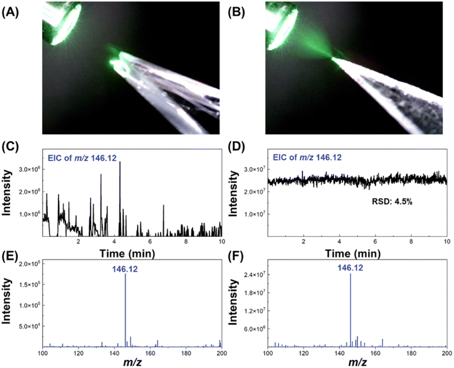 | ||
| Fig. 3 The electrospray plume of (A) an unetched 2D nESI emitter and (B) an etched 3D nESI emitter. The EIC of ACh (m/z 146.12) was obtained from (C) an unetched 2D nESI emitter and (D) an etched 3D nESI emitter. Mass spectra were obtained from (E) an unetched 2D nESI emitter and (F) an etched 3D nESI emitter. The solvent used was methanol–water 50:50 containing 1% formic acid (FA); the flow rate was 500 nL min−1; the applied nESI voltage was +4000 V. | ||
The mass spectral signal intensities of ACh at different injection flow rates are shown in Fig. S12.† As the flow rate increased from 62.5 nL min−1 to 500 nL min−1, the signal intensity of ACh increased, due to more samples being ionized by electrospray and detected by the mass spectrometer. Although the average signal intensity of ACh increased at a flow rate of 1000 nL min−1, its RSD also increased significantly. The EICs of ACh at flow rates of 62.5 nL min−1, 500 nL min−1, and 1000 nL min−1 are shown in the inset of Fig. S12.† It may be because the flow rate was too fast at 1000 nL min−1, and the sample reaching the emitter cannot be completely ionized by electrospray, resulting in an accumulation of excess sample at the tip of the emitter, which affected the stability of the electrospray ionization. Under the optimized parameters (4.0 kV and 500 nL min−1), the established glass microfluidic chip coupled with the mass spectrometry system could detect ACh with an RSD of 6.6% for 30 min (Fig. S13†), demonstrating that the system could perform stable electrospray mass spectrometric detection over a long period of time.
Detection of neurochemicals with the glass droplet microfluidic chip-MS system
The established glass microfluidic chip-MS system was used for detecting the content of ACh in aqueous droplets. Firstly, a glass microfluidic chip with a T-junction structure (Fig. S14†) was designed for droplet generation and the channel diameter of the bonded glass chip is 50 μm. Fig. 4A shows the schematic diagram of the glass droplet microfluidic chip-MS system. During the nESI MS detection of droplets, a Dino-lite microscope equipped with a digital camera was used to monitor the moving droplets to determine their size and frequency. QX200™ droplet generation oil was used as the oil phase, and an aqueous solution of ACh (50 μmol L−1 in 1% FA in methanol–water 50:50) was used as the aqueous phase. The microscope image of the generated droplets at 80 mbar for the oil phase and 80 mbar for the aqueous phase is shown in Fig. 4B, with a droplet size of about 220 pL and a droplet generation frequency of about 2.6 Hz. Fig. 4C shows the comparison between the droplet frequency recorded by the Dino-lite microscope and the correlated signal frequencies detected by MS. The results illustrated that the frequencies of the peaks observed in MS detection of droplets (TIC and EIC of ACh) were consistent with the signal sequences obtained by video recording. The results demonstrated that continuous fluid-assisted etched nESI emitters on the glass microfluidic chip-MS system enable the analysis of neurochemicals in every generated droplet.
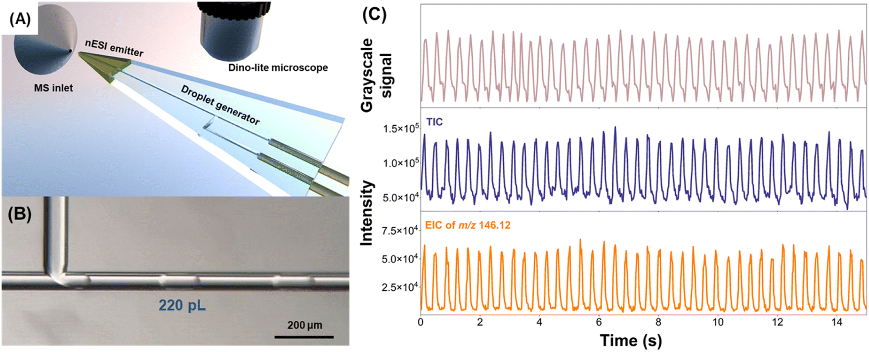 | ||
| Fig. 4 (A) Schematic diagram of the glass droplet microfluidic chip-MS system. (B) Microscope image of droplets produced by a microfluidic chip. (C) Grayscale signal obtained through the Dino-lite microscope, and total ion chromatogram (TIC) and EIC of ACh during droplet MS detection. | ||
Furthermore, the integration of monolithic emitters was compared with external nESI emitters on a glass microfluidic chip. Since both the glass microfluidic chip and the external emitter are rigid structures, there is inevitably a dead volume at the connection, which is different from the flexible structure of the PDMS chip. The wet etching method was used to etch the channels of the glass chip, which belonged to isotropic etching. At the connecting capillary channel, an arc-shaped void was formed, which could not guarantee a perfect fit between the external capillary and chip channel (Fig. S15A†). When using epoxy glue to fix the external emitter to the glass microfluidic chip channel, the dead volume at the connection is shown in Fig. S15.† The resulting dead volume would lead to the accumulation and coalescence of droplets. The commonly used capillary outer diameter is 360 μm, and the capillary connection channel on the microfluidic chip is about 400 μm. The volume of the area marked I in Fig. S15D† is calculated to be approximately 7 nL, and a rough calculation of the total dead volume at the junction exceeds 50 nL. For nanoliter samples, the dead volume may be negligible, but in this study, the droplet volume was approximately 200 pL. The dead volume is at least two orders of magnitude larger than the droplet volume, which affects the droplet passage and cannot be ignored.
The investigation of the effect of voltage on the signal intensity of ACh is shown in Fig. S16.† At 1100 V, the voltage was insufficient to produce stable electrospray, resulting in low signal intensity. At 2200 V, the voltage was too high and it was difficult to distinguish the EIC of ACh from those of individual droplets. At 1400 V, the signal intensity of ACh was high and relatively stable. Fig. S17† shows the effect of droplet size on MS signals. As the droplet size increased, both the MS intensity and the ACh EIC peak area of the droplet increased. In addition, the established glass droplet microfluidic chip-MS system was proven to have good stability. Fig. S18† shows that the RSD of the ACh signal intensity of 22369 droplets detected in approximately 180 min is 9.1%, and the RSD of the ACh EIC peak area of the droplet is 13.5%.
We explored the impact of the oil phase on the detection of molecules of interest in the aqueous phase. The main component of the oil phase we used was HFE7500, with a boiling point of 128 °C. As shown in Fig. S19,† the oil phase spray could enter the mass spectrometer. The temperature of the ion transfer tube was 350 °C, which would cause the oil phase to volatilize in the ion transfer tube. A low concentration of analyte (50 nmol L−1 ACh) was used to explore the impact of impurities in the oil on the detection (Fig. S20†). The intensity of 50 nmol L−1 ACh was about 2.04 × 10⁶ in the continuous phase and 1.65 × 10⁶ in the droplets, indicating that the signal intensity of the analyte in the droplet was slightly reduced, but it would not be seriously affected. There was a new peak at m/z 146.10 that may be an impurity peak in the oil phase, but if a high-resolution mass spectrometer was used, it would not affect the analysis of the results. The effect of ACh concentration on the signal intensity of droplets is shown in Fig. S21.† The concentrations of ACh detected were 25, 50, 100, 250 and 500 nmol L−1, and the results were linearly correlated with a correlation coefficient of 0.95.
Measuring the concentration dynamics of neurochemicals in vivo is an effective way to investigate brain function.44,45 Droplet-MS enables high temporal resolution monitoring of cerebrospinal fluid (CSF) in vivo by avoiding Taylor dispersion. To determine the potential of the established system for in vivo applications, rat CSF was used to test the performance of the established glass droplet microfluidic chip-MS system. A high-resolution mass spectrometer (Thermo Scientific Orbitrap Eclipse Tribrid) was used to detect CSF in the droplets, which helped identify its neurochemicals based on precise molecular weight and increased the sensitivity of the detection. Fig. 5A shows the TIC of CSF in the droplet microfluidics detected by MS, and Fig. 5B shows the mass spectrum of CSF in the droplet. Through accurate mass measurement in structural identification using tandem mass spectrometry (Fig. S22†), it was confirmed that ten neurochemicals, choline, acetylcholine, glutamine, serine, 3,4-dihydroxybenzeneacetic acid, tyrosine, histamine, 3-methoxy-tyramine, phenylalanine, and dopamine, were detected in the rat CSF (Table S1†). The above results indicated that the established glass droplet microfluidic chip-MS system can simultaneously detect multiple neurochemicals with high sensitivity in complex biological matrices.
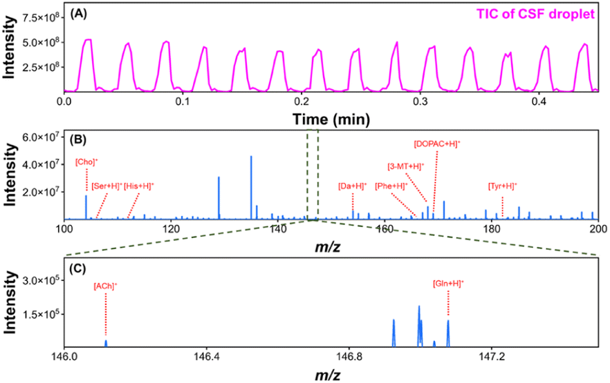 | ||
| Fig. 5 (A) TIC and (B) mass spectrum of a rat CSF droplet analyzed with the glass microfluidic chip-MS system. (C) A partially enlarged view of the rectangular marked area of (B). | ||
Conclusions
In summary, a simple and effective continuous fluid-assisted etching method was proposed in this study to fabricate monolithically integrated nESI emitters. Unlike the previous manual grinding technique, this method uses a standard etching process that allows for the mass production of integrated glass microfluidic chips with nESI emitters. The etched emitter can perform stable nESI detection over 30 min. The glass microfluidic chip integrates a T-junction droplet generator and an etched nESI emitter, which can effectively analyze neurochemicals in picoliter-volume aqueous droplets by nESI-MS. The system was successfully applied to detect ten neurochemicals in rat CSF droplets. The established glass droplet microfluidic chip-MS system has the potential to be widely used in various fields in the future, such as in vivo neurochemical monitoring, single cell analysis, and other fields in the future.Experimental section
Monolithic 3D nESI emitter fabrication
The ESI† contains detailed descriptions of chemicals, materials and instrumentations. The design and preparation of the glass microchip are described in the ESI.† The preparation of monolithic 3D nESI emitters was mainly divided into two parts: one was precision cutting and the other was fluid-assisted etching. In order to ensure that the tip was located in the center of the fluid channel after cutting, a dicing machine (Model 7120, ADT Ltd., Yokneam, Israel) with a blade thickness of 0.32 mm was used for precise cutting, and designed cutting lines (width of 20 μm) were used to assist in the precise positioning of cutting (Fig. S1†). The capillary fixed on the chip was connected to a syringe pump to drive methanol. A Teflon beaker was used as an etching reactor in which 30 mL hydrofluoric acid (HF) solution with various concentrations (20%, 30%, and 40%) was added. The syringe pump (Pump22, Harvard, USA) was run before etching to ensure that the chip channel was first filled with methanol and the chip tip was below the level of the HF solution, and then the magnetic stirrer was turned on (note: the hydrofluoric acid solution was covered with silicone oil to prevent HF evaporation. This experiment should be conducted in a fume hood). After etching, the chip tip was rinsed with a large amount of deionized (DI) water.Hydrophobic pretreatment of channels and conductive layer preparation
The hydrophobic modification of the glass chip internal channel was used of trichloro (1H,1H,2H,2H-perfluorooctyl) silane. The conductive layer of the 3D nESI emitter was prepared through a sputter coating process. In this experiment, a layer of metallic Ti was first sputtered on a glass substrate, and then Au was sputtered. Such a metal combination helps improve the adhesion of the Au layer on the glass surface and ensures the uniformity and density of the metal coating on the nESI emitter, thereby ensuring the stability of the electrospray (see the details in the ESI†).Droplet generation and MS detection
To control the flow rate of the continuous phase (QX200™ droplet generation oil) and dispersed phase, two pressure pumps (Flow-EZ, LUFEZ7000, Fluigent) were used. A mass spectrometer with a 50 Hz scanning speed (Bruker Maxis Impact) was used for the detection of ACh droplets. A mass spectrometer (Orbitrap Eclipse Tribrid, Thermo Scientific, USA) was used to detect cerebrospinal fluid in the droplets. See the ESI† for other details on the coupling mode between the microchip and the MS.Data availability
Supporting data are available upon request.Author contributions
X. W., G. G. and Yaoyao Z. conceived the study. X. W., Yaoyao Z., and Z. G. designed the chip and MS detection experiments. Z. G. and Yingqi Z. performed the chip fabrication. Z. G., and Yingqi Z. prepared the materials and performed the MS detection. Z. G., Yaoyao Z., and Y. C. performed the data analysis. Z. J. performed the simulations. X. W., Yaoyao Z., and Z. G. wrote the review and edited the manuscript. Yaoyao Z., G. G. and X. W. supervised the projects. All authors discussed the results and commented on the manuscript.Conflicts of interest
There are no conflicts to declare.Acknowledgements
This work was supported by the National Natural Science Foundation of China (No. 22204002 and 22127805) and the Beijing Outstanding Young Scientist Program (BJJWZYJH01201910005017).Notes and references
- L. Mazutis, J. Gilbert, W. L. Ung, D. A. Weitz, A. D. Griffiths and J. A. Heyman, Single-cell analysis and sorting using droplet-based microfluidics, Nat. Protoc., 2013, 8, 870–891 CrossRef CAS PubMed.
- C. I. D'Amico, D. A. Polasky, D. J. Steyer, B. T. Ruotolo and R. T. Kennedy, Ion mobility-mass spectrometry coupled to droplet microfluidics for rapid protein structure analysis and drug discovery, Anal. Chem., 2022, 94, 13084–13091 CrossRef PubMed.
- Y. Ding, P. D. Howes and A. J. deMello, Recent advances in droplet microfluidics, Anal. Chem., 2020, 92, 132–149 CrossRef CAS PubMed.
- F. Lan, B. Demaree, N. Ahmed and A. R. Abate, Single-cell genome sequencing at ultra-high-throughput with microfluidic droplet barcoding, Nat. Biotechnol., 2017, 35, 640–646 CrossRef CAS PubMed.
- M. R. Willner, K. S. McMillan, D. Graham, P. J. Vikesland and M. Zagnoni, Surface-enhanced raman scattering based microfluidics for single-cell analysis, Anal. Chem., 2018, 90, 12004–12010 CrossRef CAS PubMed.
- M. Schirmer, K. Wink, S. Ohla, D. Belder, A. Schmid and C. Dusny, Conversion efficiencies of a few living microbial cells detected at a high throughput by droplet-based ESI-MS, Anal. Chem., 2020, 92, 10700–10708 CrossRef CAS PubMed.
- Y. Wu, L. Zhao, Y. Chang, L. Zhao, G. Guo and X. Wang, Ultra-thin temperature controllable microwell array chip for continuous real-time high-resolution imaging of living single cells, Chin. Chem. Lett., 2021, 32, 3446–3449 CrossRef CAS.
- Y. Zhu and Q. Fang, Integrated droplet analysis system with electrospray ionization-mass spectrometry using a hydrophilic tongue-based droplet extraction interface, Anal. Chem., 2010, 82, 8361–8366 CrossRef CAS PubMed.
- C. M. Huang, Y. Zhu, D. Q. Jin, R. T. Kelly and Q. Fang, Direct surface and droplet microsampling for electrospray ionization mass spectrometry analysis with an integrated dual-probe microfluidic chip, Anal. Chem., 2017, 89, 9009–9016 CrossRef CAS PubMed.
- Y. Zhang, S. Kim, W. Shi, Y. Zhao, I. Park, C. Brenden, H. Iyer, P. Jha, R. Bashir, J. V. Sweedler and Y. Vlasov, Droplet-assisted electrospray phase separation using an integrated silicon microfluidic platform, Lab Chip, 2021, 22, 40–46 RSC.
- Y. Zhang, K. Li, Y. Zhao, W. Shi, H. Iyer, S. Kim, C. Brenden, J. V. Sweedler and Y. Vlasov, Attomole-level multiplexed detection of neurochemicals in picoliter droplets by on-chip nanoelectrospray ionization coupled to mass spectrometry, Anal. Chem., 2022, 94, 13804–13809 CrossRef CAS PubMed.
- N. Nordman, S. Lauren, T. Kotiaho, S. Franssila, R. Kostiainen and T. Sikanen, Interfacing microchip isoelectric focusing with on-chip electrospray ionization mass spectrometry, J. Chromatogr. A, 2015, 1398, 121–126 CrossRef CAS PubMed.
- C. Dietze, C. Hackl, R. Gerhardt, S. Seim and D. Belder, Chip-based electrochromatography coupled to ESI-MS detection, Electrophoresis, 2016, 37, 1345–1352 CrossRef CAS PubMed.
- S. M. Tahka, A. Bonabi, V. P. Jokinen and T. M. Sikanen, Aqueous and non-aqueous microchip electrophoresis with on-chip electrospray ionization mass spectrometry on replica-molded thiol-ene microfluidic devices, J. Chromatogr. A, 2017, 1496, 150–156 CrossRef CAS PubMed.
- C. Lotter, J. J. Heiland, S. Thurmann, L. Mauritz and D. Belder, HPLC-MS with glass chips featuring monolithically integrated electrospray emitters of different geometries, Anal. Chem., 2016, 88, 2856–2863 CrossRef CAS PubMed.
- C. Lotter, E. Poehler, J. J. Heiland, L. Mauritz and D. Belder, Enantioselective reaction monitoring utilizing two-dimensional heart-cut liquid chromatography on an integrated microfluidic chip, Lab Chip, 2016, 16, 4648–4652 RSC.
- C. Lotter, J. J. Heiland, V. Stein, M. Klimkait, M. Queisser and D. Belder, Evaluation of pressure stable chip-to-tube fittings enabling high-speed chip-HPLC with mass spectrometric detection, Anal. Chem., 2016, 88, 7481–7486 CrossRef CAS.
- N. T. Hartner, C. R. Raddatz, C. Thoben, S. K. Piendl, S. Zimmermann and D. Belder, On-line coupling of chip-electrochromatography and ion mobility spectrometry, Anal. Chem., 2020, 92, 15129–15136 CrossRef CAS.
- K. Wink, M. van der Loh, N. Hartner, M. Polack, C. Dusny, A. Schmid and D. Belder, Quantification of biocatalytic transformations by single microbial cells enabled by tailored integration of droplet microfluidics and mass spectrometry, Angew. Chem., Int. Ed., 2022, 61, e202204098 CrossRef CAS.
- R. J. Beulig, R. Warias, J. J. Heiland, S. Ohla, K. Zeitler and D. Belder, A droplet-chip/mass spectrometry approach to study organic synthesis at nanoliter scale, Lab Chip, 2017, 17, 1996–2002 RSC.
- A. Lashkaripour, C. Rodriguez, L. Ortiz and D. Densmore, Performance tuning of microfluidic flow-focusing droplet generators, Lab Chip, 2019, 19, 1041–1053 RSC.
- P. Zhu and L. Wang, Passive and active droplet generation with microfluidics: a review, Lab Chip, 2016, 17, 34–75 RSC.
- D. A. Vargas Medina, E. V. S. Maciel and F. M. Lanças, Miniaturization of liquid chromatography coupled to mass spectrometry. 3. achievements on chip-based LC–MS devices, TrAC, Trends Anal. Chem., 2020, 131, 116003 CrossRef CAS.
- H. Tavakoli, W. Zhou, L. Ma, S. Perez, A. Ibarra, F. Xu, S. Zhan and X. Li, Recent advances in microfluidic platforms for single-cell analysis in cancer biology, diagnosis and therapy, TrAC, Trends Anal. Chem., 2019, 117, 13–26 CrossRef CAS PubMed.
- S. Sohrabi, N. Kassir and M. Keshavarz Moraveji, Droplet microfluidics: fundamentals and its advanced applications, RSC Adv., 2020, 10, 27560–27574 RSC.
- X. Wang, L. Yi, N. Mukhitov, A. M. Schrell, R. Dhumpa and M. G. Roper, Microfluidics-to-mass spectrometry: a review of coupling methods and applications, J. Chromatogr. A, 2015, 1382, 98–116 CrossRef CAS PubMed.
- S. Geromanos, G. Freckleton and P. Tempst, Tuning of an electrospray ionization source for maximum peptide-ion transmission into a mass spectrometer, Anal. Chem., 2000, 72, 777–790 CrossRef CAS PubMed.
- T. C. Rohner, J. S. Rossier and H. H. Girault, Polymer microspray with an integrated thick-film microelectrode, Anal. Chem., 2001, 73, 5353–5357 CrossRef CAS PubMed.
- E. E. Kempa, C. A. Smith, X. Li, B. Bellina, K. Richardson, S. Pringle, J. L. Galman, N. J. Turner and P. E. Barran, Coupling droplet microfluidics with mass spectrometry for ultrahigh-throughput analysis of complex mixtures up to and above 30 Hz, Anal. Chem., 2020, 92, 12605–12612 CrossRef CAS PubMed.
- D. J. Steyer and R. T. Kennedy, High-throughput nanoelectrospray ionization-mass spectrometry analysis of microfluidic droplet samples, Anal. Chem., 2019, 91, 6645–6651 CrossRef CAS PubMed.
- L. Sainiemi, T. Sikanen and R. Kostiainen, Integration of fully microfabricated, three-dimensionally sharp electrospray ionization tips with microfluidic glass chips, Anal. Chem., 2012, 84, 8973–8979 CrossRef CAS PubMed.
- Y. Zhu, J.-Z. Pan, Y. Su, Q.-H. He and Q. Fang, Fabrication of low-melting-point alloy microelectrode and monolithic spray tip for integration of glass chip with electrospray ionization mass spectrometry, Talanta, 2010, 81, 1069–1075 CrossRef CAS PubMed.
- P. Hoffmann, M. Eschner, S. Fritzsche and D. Belder, Spray performance of microfluidic glass devices with integrated pulled nanoelectrospray emitters, Anal. Chem., 2009, 81, 7256–7261 CrossRef CAS PubMed.
- J. S. Mellors, V. Gorbounov, R. S. Ramsey and J. M. Ramsey, Fully integrated glass microfluidic device for performing high-efficiency capillary electrophoresis and electrospray ionization mass spectrometry, Anal. Chem., 2008, 80, 6881–6887 CrossRef CAS PubMed.
- A. G. Chambers and J. M. Ramsey, Microfluidic dual emitter electrospray ionization source for accurate mass measurements, Anal. Chem., 2012, 84, 1446–1451 CrossRef CAS.
- A. G. Chambers, J. S. Mellors, W. H. Henley and J. M. Ramsey, Monolithic integration of two-dimensional liquid chromatography-capillary electrophoresis and electrospray ionization on a microfluidic device, Anal. Chem., 2011, 83, 842–849 CrossRef CAS PubMed.
- P. Hoffmann, U. Hausig, P. Schulze and D. Belder, Microfluidic glass chips with an integrated nanospray emitter for coupling to a mass spectrometer, Angew. Chem., Int. Ed., 2007, 46, 4913–4916 CrossRef CAS PubMed.
- A. J. Peretzki, S. Schmidt, E. Flachowsky, A. Das, R. F. Gerhardt and D. Belder, How electrospray potentials can disrupt droplet microfluidics and how to prevent this, Lab Chip, 2020, 20, 4456–4465 RSC.
- S. Fritzsche, P. Hoffmann and D. Belder, Chip electrophoresis with mass spectrometric detection in record speed, Lab Chip, 2010, 10, 1227–1230 RSC.
- C. Benz, M. Boomhoff, J. Appun, C. Schneider and D. Belder, Chip-based free-flow electrophoresis with integrated nanospray mass-spectrometry, Angew. Chem., Int. Ed., 2015, 54, 2766–2770 CrossRef CAS.
- F. Schwarzkopf, T. Scholl, S. Ohla and D. Belder, Improving sensitivity in microchip electrophoresis coupled to ESI-MS/MS on the example of a cardiac drug mixture, Electrophoresis, 2014, 35, 1880–1886 CrossRef CAS PubMed.
- S. Fritzsche, S. Ohla, P. Glaser, D. S. Giera, M. Sickert, C. Schneider and D. Belder, Asymmetric organocatalysis and analysis on a single microfluidic nanospray chip, Angew. Chem., Int. Ed., 2011, 50, 9467–9470 CrossRef CAS PubMed.
- K. Takeuchi, F. W. Mu, Y. Matsumoto and T. Suga, Room temperature wafer bonding of glass using aluminum oxide intermediate layer, Adv. Mater. Interfaces, 2021, 8, 2001741 CrossRef CAS.
- P. Song, N. D. Hershey, O. S. Mabrouk, T. R. Slaney and R. T. Kennedy, Mass spectrometry “sensor” for in vivo acetylcholine monitoring, Anal. Chem., 2012, 84, 4659–4664 CrossRef CAS PubMed.
- G. Petit-Pierre, P. Colin, E. Laurer, J. Deglon, A. Bertsch, A. Thomas, B. L. Schneider and P. Renaud, In vivo neurochemical measurements in cerebral tissues using a droplet-based monitoring system, Nat. Commun., 2017, 8, 1239 CrossRef PubMed.
Footnote |
| † Electronic supplementary information (ESI) available. See DOI: https://doi.org/10.1039/d4sc01700e |
| This journal is © The Royal Society of Chemistry 2024 |