
 Open Access Article
 This Open Access Article is licensed under a Creative Commons Attribution-Non Commercial 3.0 Unported Licence
The effects of droplet stabilization by surfactants and nanoparticles on leakage, cross-talk, droplet stability, and cell adhesion†
Jorik Waeterschoot *a,
Emine Kayahana,
Jolien Breukersb,
Jeroen Lammertynb and
Xavier Casadevall i Solvas*a
*a,
Emine Kayahana,
Jolien Breukersb,
Jeroen Lammertynb and
Xavier Casadevall i Solvas*a
aBiomimetics Group, Divison of Mechatronics, Biostatistics and Sensors (MeBios), Department of Biosystems, KU Leuven, Willem de Croylaan 42, 3001 Leuven, Belgium. E-mail: jorik.waeterschoot@kuleuven.be; xevi.casadevall@kuleuven.be
bBiosensors Group, Divison of Mechatronics, Biostatistics and Sensors (MeBios), Department of Biosystems, KU Leuven, Willem de Croylaan 42, 3001 Heverlee, Belgium
First published on 1st August 2024
Abstract
Partially fluorinated nanoparticles (FNPs) have been proposed as a promising alternative for stabilising aqueous droplets in fluorinated oils. The exceptional energetic stability of FNPs at the droplet interface holds the potential for minimising leakage, enhancing stability, and promoting improved cell adhesion. However, their lower diffusion coefficient compared to surfactants presents challenges in achieving rapid droplet stabilisation, which is important in microfluidics applications. While several studies have focused on some of these aspects, a comprehensive study and direct comparison with conventional fluorosurfactants is still missing. In this manuscript, we undertake an examination and comparison of four crucial facets of both FNP- and surfactant-stabilised droplets: leakage of compounds, emulsion stability, droplet formation dynamics and cell adhesion. Contrary to what has previously been claimed, our findings demonstrate that FNPs only reduce leakage and cross-talk in very specific cases (e.g., resorufin), failing to provide enhanced compartmentalisation for highly hydrophobic dyes (e.g., rhodamine dyes). On the other hand, FNP-stabilised droplets indeed exhibit greater long-term stability compared to their surfactant-stabilised counterparts. Regarding the size of droplets generated via a diversity of microfluidic methods, no significant differences were observed between FNP-stabilised and surfactant-stabilised droplets. Finally, the previously reported improvements in cell adhesion and spreading on FNP-stabilised interfaces is limited to flat oil/water (o/w) interfaces and could not be observed within droplets. These comprehensive analyses shed light on the nuanced performance of FNPs and commercial fluorosurfactants as stabilising agents for aqueous droplets in fluorinated oils, contributing valuable insights for choosing the correct formulation for specific droplet-based microfluidics applications.
Droplet-based microfluidics is becoming a widely used emerging technology for the miniaturisation and automation of chemical and biological assays.1 In droplet-based microfluidics, an aqueous phase is encapsulated in micron-sized droplets that can be regarded as miniaturised reaction vessels which can be individually manipulated and analysed. These droplets are used for a wide variety of applications such as (combinatorial) drug screening,2,3 antibiotics screening,4 directed evolution,5 single cell analysis,6,7 studying interfacial dynamics,8 …. Droplet production is typically performed in microfluidic chips, with a wide diversity of droplet production geometries enabling droplet formation e.g., crossflow (or T-junction), flow focusing, co-flow, step-emulsification, ….9,10 Generally, an aqueous phase in which a (bio)chemical reaction is performed is segmented within an inert oil phase (typically fluorinated) which is used as carrier phase and in which a surfactant is added to stabilise the droplets against coalescence.1
To effectively utilise such droplets as individual reaction vessels, it is imperative to prevent the transfer of materials from one droplet to another and/or the loss of these materials into the surrounding carrier phase. Achieving this crucial encapsulation relies primarily on the selection of an appropriate system consisting of a carrier phase and a stabilising agent. Fluorinated oils, composed of perfluorocarbon compounds bearing highly polarised C–F bonds, have emerged as a pivotal component in this pursuit.11–13 These fluorinated oils exhibit notable characteristics that render them exceptionally suited for use in droplet-based microfluidics. Their inherently low hydrogen-bonding capacity11 and weak London dispersion forces12 result in minimal solubility of both polar and non-polar substances, effectively preventing loss of encapsulated compounds into the carrier phase. Remarkably, these oils also possess a high capacity for dissolving gases, thereby promoting the survival of enclosed biological entities.14 Furthermore, unlike certain other oils, fluorinated oils do not induce swelling in polydimethylsiloxane (PDMS) microfluidic devices.15 To prevent droplets from merging, though, stabilising reagents are typically needed. Traditionally, these have relied on fluorinated surfactants featuring perfluorinated carbon chains linked to hydrophilic groups. Surfactants with longer fluorocarbon tails, such as perfluoropolyethers (PFPE), have been shown to extend droplet stability.1,16–19
Notably, two prominent PFPE-based surfactants, ‘Krytox’ by DuPont and ‘RAN’ by RAN Biotechnologies (see Fig. 1), have gained widespread usage in droplet-based microfluidics. RAN, a PFPE-PEG-PFPE block copolymer, is well-documented for its ability to yield stable droplets with biocompatible interfaces that are also significantly robust against leakage of hydrophilic compounds,20–22 however for more hydrophobic compounds leakage remains problematic. In contrast, Krytox, a PFPE-carboxylic acid variant, offers cost-effectiveness but is susceptible to increased leakage due to interactions between the carboxylic acid moiety and encapsulated compounds.1
 | ||
| Fig. 1 Three different droplet stabilisers used in this paper. (A) RAN, (B) Krytox, (C) FNPs. | ||
Despite the remarkable attributes of fluorinated oil-surfactant systems in droplet-based microfluidics, challenges persist in preventing the leakage of certain compounds into the carrier phase or mitigating cross-talk between droplets.23 It is important to delineate between two distinct phenomena in this context: ‘cross-talk’ and ‘leakage’. ‘Cross-talk’ refers to the transfer of compounds between droplets, whereas ‘leakage’ pertains to the undesired loss of droplet contents into the surrounding oil phase. These two effects arise from a diversity of mechanisms which include diffusion-driven partitioning, micellar-induced transport and surfactant–compound interactions.4,23,24
Previous investigations have delved into the phenomenon of leakage from droplets stabilised by surfactants, focusing on twelve distinct water-soluble dyes.23 These studies sought to elucidate the influence of surfactant concentration, geometry and molecular weight of surfactants on the propensity for dye leakage. In the pursuit of comprehensive insights, distribution coefficients (log![[thin space (1/6-em)]](https://www.rsc.org/images/entities/char_2009.gif) D) were calculated for all fluorophores, wherein the logD represents the ratio of a compound's concentration in two immiscible liquids at equilibrium. This parameter encompasses the solubilities of all ionised and non-ionised species of the compound, with negative logD values signifying hydrophilic dyes and positive values indicating hydrophobic ones. The findings revealed that hydrophilic dyes with negative logD values exhibited stable retention within droplets, irrespective of the buffer medium. However, exceptions were observed among hydrophobic fluorophores, particularly those characterised by low molecular weight and planar molecular structures.23 This systematic exploration significantly contributed to our understanding of leakage phenomena from droplets into the surrounding oil phase.
D) were calculated for all fluorophores, wherein the logD represents the ratio of a compound's concentration in two immiscible liquids at equilibrium. This parameter encompasses the solubilities of all ionised and non-ionised species of the compound, with negative logD values signifying hydrophilic dyes and positive values indicating hydrophobic ones. The findings revealed that hydrophilic dyes with negative logD values exhibited stable retention within droplets, irrespective of the buffer medium. However, exceptions were observed among hydrophobic fluorophores, particularly those characterised by low molecular weight and planar molecular structures.23 This systematic exploration significantly contributed to our understanding of leakage phenomena from droplets into the surrounding oil phase.
In contrast to the conventional approach of modifying molecular surfactants to address leakage concerns, Pan et al. proposed a novel strategy employing fluorinated silica nanoparticles (FNPs) as stabilising agents for droplets (i.e., Pickering emulsions).25–28 In their reports, FNPs are claimed to become more energetically trapped at the droplet interface compared to surfactant molecules, leading to reduced mobility.29 Crucially, they eliminate the potential for micelle formation, resulting in droplets characterised by lower leakage rates. For instance, in their experiments they provide evidence that resorufin (a slightly hydrophobic dye) remains confined within FNP-stabilised droplets, while leakage occurs in surfactant-stabilised counterparts.30 Still, a thorough study investigating the behaviour of different dyes in different carrier systems has, so far, been lacking.
In addition to reducing cross-talk and leakage, FNP-stabilised droplets may offer enhanced stability compared to their surfactant-stabilised counterparts, potentially enabling extended storage periods.28,30 Such effects, though, have not yet been investigated in depth to date. Furthermore, previous studies have hinted at the potential of FNPs to serve as substrates for cell adhesion and growth within microfluidic droplets,25,31 but research in this domain has remained limited to illustrative demonstrations.
Despite their postulated advantages, the production of FNP-stabilised droplets presents its own set of intricacies. Due to their larger size and associated lower diffusion rates compared to surfactant molecules, the time required for droplet stabilisation with FNPs is typically extended. Consequently, specialised microfluidic chip designs are needed to facilitate stable droplet formation. Typically, these consist of elongated serpentine channels that afford sufficient time for FNPs to diffuse over the droplet interface before droplets become in contact with each other.27,32 Alternatively, microfluidic chips featuring additional inlets are operated to enable the deposition of highly concentrated particle solutions in close proximity to the droplet interface.32 All these approaches, though, focus on droplet generation via flow-focusing strategies and a comparative study for other droplet production strategies (e.g., step-emulsification) is still missing.
In view of the significant knowledge gaps on our understanding of the performance of FNPs for droplet-based microfluidic applications, we carried out a comprehensive exploration of several important features of these stabilising agents in these systems. First, leakage and cross-talk phenomena were analysed and compared to two surfactants (Krytox and RAN) typically used to stabilise droplets, which was not yet done in previous research. To do this, we introduced a statistical methodology to rigorously investigate and quantify these phenomena. Notably, this study marks the first systematic comparison of leakage and cross-talk behaviours between droplets stabilised with surfactants and FNPs. To examine this phenomena, the behaviour of 15 different dyes encapsulated within droplets was examined for four different buffer conditions by combining these with empty droplets and monitoring fluorescence on day zero and day one. Additionally, we explored different microfluidic strategies for droplet production and stabilisation, encompassing three distinct flow-focusing configurations, a T-junction, a combination of step-emulsification and flow focusing and two step-emulsification devices. Furthermore, we assessed the validity of the assumption that FNPs are energetically more favourably trapped at the droplet interface than surfactants, comparatively reducing droplet coalescence. To evaluate this aspect, we subjected droplets to various stress conditions, including PCR thermocycling and incubation at room temperature, in a refrigerator and in an incubator for extended periods of time, whereupon droplet size was monitored over time to discern any trends in polydispersity. Finally, we investigated the potential enhancement in adhesion of anchorage-dependant cells on FNP-stabilised interfaces when compared to surfactants.
These comprehensive analyses of four important functionalities in the field of droplet-based microfluidics address some of the most relevant knowledge gaps currently present in the utilisation of FNPs as droplet stabilisers and allow us to provide an assessment of the advantages and disadvantages associated with their use in this field.
1. Materials and methods
Dulbecco's phosphate-buffered saline (DPBS) and Dulbecco's modified eagle medium (DMEM) two cell mediums used in the leakage and cell adhesion assays, fetal bovine serum (FBS) and 0.05% trypsin-EDTA for cell culture, 0.56 × 1.07 mm PTFE microbore tubing and sterican G23 × 1 1/4 needles for microfluidic chip operation, Nalgene Oak Ridge High-Speed PPCO Centrifuge Tubes for FNP washing are all acquired from Thermofisher. Epidermal growth factor (EGF) and hydrocortisone for cell culture were obtained from Bio-Techné and Sigma Aldrich, respectively. CellCarrier-96 Ultra Microplates, tissue culture treated were purchased from PerkinElmer. Tetraethyl orthosilicate (TEOS), 28% ammonia and 99.8% absolute ethanol for particle production, propylene glycol monomethyl ether acetate (PGMEA), trichloro(1H,1H,2H,2H-perfluorooctyl)silane), corning 75 mm × 25 mm glass microscopy slides for microfluidic chip fabrication, tris(hydroxymethyl)aminomethane (Tris) and bovine serum albumine (BSA) compounds of the buffer solutions were purchased from Sigma. 3 inch Si wafers as base for the master wafer were purchased from MicroChemicals GmbH. The chip material, Sylgard 184 PDMS was obtained from Farnell. 1 mm biopsy punchers and 1 mL plastic syringes essential for chip operation were purchased from VWR. Fast read cell counting slides used for droplet imaging were obtained from Novolab and SU8 2002, SU8 2015, SU8 2075 from Kayaku Advanced Materials. Photoplots were produced by Microlitho (UK). The fluorinated oil HFE 7500 was purchased Fluorochem, Uranyl acetate from Electron Microscopy Sciences. RAN 008 was obtained from RAN Biotechnologies and Krytox 157 FSH from Costenoble.15 different dyes were compared in the droplet leakage assay: fluorescein sodium salt (Fl), 8-hydroxypyrene-1,3,6-trisulfonic acid trisodium salt (Pyr), sulforhodamine 101 (SulfRhod), rhodamine 101 (Rhod101), rhodamine B (RhodB), rhodamine 6G (Rhod6G), resorufin (Res) and alizarin red (AZ) were purchased from Sigma Aldrich. Nile red (NR), 4′,6-diamidino-2-phenylindole dihydrochloride (DAPI), eosin-5-maleimide (EMA), Alexa fluor 350 (AF350), Alexa Fluor 488 (AF488), Alexa Fluor 568 (AF568) were obtained from Thermofisher. Sulfo-cy5 NHS ester (Cy5) was acquired from fluoroProbes and sulfo-cyanine 7 NHS ester (Cy7) from LumiProbe. 10 mM stock solutions were prepared in DMSO which were diluted 100× upon use for droplet production in the correct aqueous solution. Chemical structures of each dye are depicted in Fig. S2 and S3.†
The distribution coefficients were calculated with Marvin Sketch 23.8 by using ChemAxon and can be retrieved in Table 2. The distribution coefficient is defined as the expected ratio of the sum of concentrations of all forms of the fluorophore (ionized plus unionized) in water and in a non polar solvent (in this case octanol) and gives a good indication of the hydrophobicity of a molecule.23 All tautomers and resonance structures of the dyes were taken into account during the calculations. The electrolyte concentrations and pH values were based on the solutions as shown in Table 1.
| DPBS | DMEM | MiliQ | Tris | |
|---|---|---|---|---|
| pH | 7.4 | 7.4 | 7.0 | 7.5 |
| Cl− ion concentration (mol dm−3) | 0.14 | 0.12 | 0.00 | 0.02 |
| Na+ and K+ ion concentration (mol dm−3) | 0.16 | 0.16 | 0.00 | 0.00 |
1.1 FNP production and characterization
100 nm silica NPs were produced via the Stöber method.33 In short 3.8 mL of TEOS was added dropwise to 114 mL ethanol and 5.7 mL of 28 w/w% ammonium hydroxide. The solution was stirred overnight. Next, 10 mL of this particle solutions was further functionalised with 7.58 × 10⁻³ mol FAS per g NPs which was added dropwise to the solution and left shaking overnight. Afterwards particle solutions were transferred to oakridge centrifuge tubes and spinned down for 30 min at 15000g. Particles were resuspend in ethanol by 10 min sonication. This cleaning process was repeated two more times. In the final wash the ethanol was replaced by HFE 7500. To remove the small amounts of leftover ethanol the particles were desiccated for at least an hour. The final concentration of NPs was chosen to be 0.1 g mL−1. The FNPs were used in this concentration unless stated otherwise.
Dynamic light scattering (DLS) was performed with the zetasizer Nano ZSP (Malvern Panalytical, UK) for analysis of (F)NP size distribution. DLS samples were transferred to a quartz cuvette (ZEN 2112) at 173° (25 °C). Each sample was measured three times with the following material properties: EtOH (refractive index: 1.287, dynamic viscosity: 1.074 cP, dielectric cte: 25.3), HFE 7500 (refractive index: 1.290, dynamic viscosity: 1.240 cP, dielectric cte: 5.8), silica particles (refractive index: 1.540).
Transmission electron microscopy (TEM) was utilised as an additional tool for particle size analysis. For the TEM a 300 mesh copper grid was glow discharged for 15 s. Next 3.5 μL sample was transferred to the grid and incubated for 5 min. After blotting samples were imaged.
Energy dispersive X-ray (EDX) composition analysis allowed for analysing successful fluorination of the silica NPs. Here the samples were oven dried at 70 °C overnight and then transferred to carbon tape. Afterwards samples were imaged with the Quanta 200 ESEM FEG (FEI, USA) with EDX system.
1.2 Microwell plate partitioning
Each of the 15 different fluorophores in DMSO was diluted up to 10 μM in a DPBS solution (5 mg mL−1 BSA). 300 μL of this solution was layered on top of a 300 μL HFE oil phase containing either an extra 10 μL of 2 w/w% RAN solution, 10 μL of 2 w/w% Krytox solution, 10 μL of 0.1 g mL−1 FNPs or an extra 10 μL of HFE (samples were prepared in triplicate). These solutions were left for incubation overnight in an eppendorf tube. Next, 150 μL of each sample solution was transferred to a 96 well plate. Fluorescence emission of the oil phases was measured with the Spectramax Id3 (Molecular Devices, USA). Samples with RAN, Krytox or FNPs were statistically compared with a one-sided Student's t-test (after background subtraction) with the hypothesis that the samples with HFE 7500 oil with no surfactant contained less fluorophores compared to the samples carrying surface reactive reagents.1.3 Microfluidic chip production
As base for the master moulds, a 3′′ Si wafer was first prepared by cleaning it with acetone and dehydrating for 10 min at 120 °C. Depending on the designs, different layer heights were produced according to the SU8 data sheet from Kayaku advanced materials (see ESI† for full protocol34–36). For an overview of all designs utilised in the droplet production tests see Fig. S1.† Three different flow focusing designs were each produced with at least two different orifice widths. Additionally, a chip combining a flow focusing with a step emulsification droplet production architecture, as well as a chip with a T-junction design and two chips with different step emulsification designs were utilised in this work. For the cell encapsulation experiments, a flow focusing design was used with a channel width, channel height and orifice width of 100, 70, and 40 μM, respectively.After master fabrication, microfluidic chips were produced by first mixing PDMS monomer and crosslinker in a 10:1 ratio. This was followed by 30 min of desiccation for air bubble removal. The mixture was poured on top of the master and cured for 2 h at 70 °C. Chips were removed from the master and 1 mm inlets/outlets were punched. Next the PDMS slabs were bonded to a glass slide after exposure to an air plasma for 90 s (18 W RF power), after which they were heated on a hotplate at 100 °C for 15 min and silanised with a 5 v/v% trichlorosilane solution and heated for 2 h at 70 °C.
1.4 Materials and imaging conditions for droplets
A total of 15 different dyes were encapsulated at a concentration of 0.01 mM in droplets stabilised by RAN, Krytox or FNPs. These experiments were performed for four different buffer conditions: DPBS, DMEM, Tris buffer (30 mM Tris, ph: 7.5, 10 mM MgCl2) and MiliQ, containing 5 mg mL−1 BSA solution essential for rapid stabilisation of droplets with FNPs. Droplets were produced with chip design 1 (20 μM thick, see Fig. S1†) with 5 μL min−1 (aqueous phase) and 10 μL min−1 oil flow rate.A volume of 10 μL of droplets containing only buffer was combined with another 10 μL of dye-encapsulating droplets. Droplet populations were imaged directly after combination and after one day of incubation by transferring 4 μL of droplet solution inside a cell-counting chamber from which brightfield and epifluorescence micrographs were captured with a Nikon Ti2 microscope.
For the on-chip leakage fluorescence imaging three dyes were selected: AF488 (a well retained dye), sulford (a moderately leaky dye), Rhod6G (a strongly leaky dye). These were imaged on the Nikon Ti2. Chip design 1 (20 μM thick, see Fig. S1†) with 1 μL min−1 (aqueous phase) and 2 μL min−1 oil flow rate utilised for droplet generation.
1.5 Determination of fluorophore leakage and cross-talk
Two populations of droplets were combined in an eppendorf tube one population with encapsulated dye and one population with only buffer solution. To asses leakage and cross-talk, fluorescence images (Nikon Ti2) were taken directly after combination of the populations (day 0) and after one day (day 1). In the absence of leakage, these two different droplet populations result in two normally-distributed populations of fluorescence intensity values: one of high fluorescence intensity and another of very dim intensity (due to light scattering effects only). This data could be fitted to a bimodal normal distributions, in which two normal distributions were weighted and summed up. The probability density distribution (pdf) of a bimodal normal distribution is given in eqn (1).
 | (1) |
With this fitting, the medians and standard deviations of two different normal distributions and the mixing parameter were calculated. If the mixing parameter was close to zero or one, the bimodal normal distribution approaches a normal distribution with only one bell-shaped curve. That indicates that there is only one droplet population instead of two indicating transfer of dye from the droplets encapsulating dye to the empty droplets. However, this parameter is not a perfect indicator of cross-talk on its own: if the medians of two bell-shaped curves are close to each other (in the case of cross-talk with two overlapping populations), the mixing parameter can still be close to 0.5. For this reason a calculation of the intersection area was used, since it provides a more accurate indication of the occurrence of cross-talk (e.g., the intersection area corresponds to the percentage of droplets that cannot be differentiated into two distinct populations). In the absence of cross-talk, the intersection area was close to zero. Based on our analysis and our experimental observations, an intersection of 10% was chosen for identifying cross-talk. For a few experiments, though, the bimodal distribution fitting was unreliable (e.g., R2 < 70), likely due to some variability in the experimental conditions at different time points. In these rare cases, the final classification was made based on the visual inspection of the data and the observations made during the experiments.
To obtain the data for the fitting images were analysed with a custom Phyton script. The location and size of the droplets were detected on the brightfield images through a Hough circle transform. The fluorescence intensities at these location were measured and averaged across each droplet. The background was detected by measuring the intensities at three different locations outside of the droplets (image background) and in pure buffer solution (buffer background). The droplet size distribution and fluorescence data were extracted from the Phyton pipeline. Then, this data was fed to a MATLAB R2023a (statistics and machine learning toolbox) to form the histograms and do further statistical analysis by fitting the data to probability distributions as described above.
To check for the leakage of fluorophores from the droplets, the percentage of droplets with an average intensity value below the background value (image background) was detected. If more then 10% of the droplets had an intensity below the background the sample was categorised as very leaky (category 4, see below). To calculate the cross-talk between the droplets, buffer background was subtracted from the fluorescence data of droplets and the resulting data were normalised between 0 and 100. This scaling provided a more suitable way for comparing different populations. The data was fitted to a bimodal normal distribution with the function “fitgmdist” with two components to represent two normal distributions. Then, a probability density between 0 and 100 was calculated based on the predicted median, standard deviation and mixing parameter, and drawn as a linear curve. In order to check for cross-talk, the intersection area of the two normal distributions was calculated by “cumtrapz” function. This function calculates the integral of the minimum values of the two probability densities by trapezoidal numerical integration. Then, histograms were generated with a hundred bins based on the raw normalised data, finally the intersection area was calculated. Based on the calculation above dye leakage and cross-talk was divided into four categories (see Fig. 4 for a visual overview).
• Category 1: more than 10% of the droplets show a lower average fluorescence intensity than the background value on day 0 indicating severe leakage of the dye into the oil phase.
• Category 2: less than 10% of the droplets show a lower average fluorescence intensity than the background value on day 0 and the bimodal distribution shows a minimal overlap of 10% on day 0 and 1. These droplets show limited leakage and severe cross-talk.
• Category 3: less than 10% of the droplets show a lower average fluorescence intensity than the background value on day 0 and the bimodal distribution shows a minimal overlap of 10% only on day 1. These droplets show limited leakage and mild cross-talk.
• Category 4: less than 10% of the droplets show a lower average fluorescence intensity than the background value on day 0 and the bimodal distribution shows an overlap of less than 10% on day 0 and 1. The droplets show limited leakage and cross-talk in this category.
1.6 Droplet storage and stability
DPBS droplets (5 mg mL−1 BSA) were generated with a diameter around 60 μM on a microfluidic chip with a flow focusing design (design 1, 20 μM height, see Fig. S1†). Droplets were stabilised by 2 w/w% RAN, 2 w/w% Krytox or 0.1 g mL−1 FNPs. These droplets were exposed to different conditions: storage at 4 °C, storage at room temperature (RT), storage in a incubator (37 °C, 5% CO2) and a PCR temperature cycle using a thermocycler (TProfessional Basic, Biometra Ltd.) were droplets were exposed to 95 °C for 5 min followed by 40 cycles of 5 s at 95 °C and 30 s at 60 °C. 5 repeats were performed for each stabilising reagent and temperature condition (100 μL sample in 0.5 μL eppendorf tube). Samples were monitored at day 0 and day 1 after 1 week and after 2 weeks and PCR samples were imaged directly after cycling. Droplet size was analysed with the phyton script described in the previous section.1.7 Cell adhesion and encapsulation
MCF-7 and MCF-10A cells were purchased from the American Tissue Culture Collection (ATCC). MCF-7 cells were cultured in DMEM/F-12 (GlutaMAX™ supplement) with 10% FBS. MCF-10A cells were cultured in DMEM (high glucose, GlutaMAX™ supplement, pyruvate) with 10% FBS, 10 ng mL−1 EGF and 0.5 μg mL−1 hydrocortisone. Cells were detached using 0.05% trypsin-EDTA, rinsed and resuspended in the corresponding cell medium at 50000 cells per mL. To study cell adhesion on different oil phases, wells of a 96-well plate were filled with 100 μL of HFE 7500, 2 w/w% Krytox in HFE 7500, 2 w/w% RAN in HFE 7500 and 0.025 g mL−1 FNPs in HFE 7500. For the latter, a FNP concentration of 0.025 g mL−1 was used to enable bright-field imaging through the oil layer. For both cell types, a cell suspension of 200 μL was added on top of each oil phase and in empty wells. Experiments were performed in triplicate. Bright-field images at 20× magnification were taken 0 h, 24 h and 48 h after cell seeding. In between measurements, the plate was placed in an incubator (37 °C, 5% CO2). To study cell adhesion in droplets, droplets were generated for HFE 7500 supplemented with RAN (2 w/w%), Krytox (2 w/w%), and FNPs (0.025 g mL−1). The droplets were generated by flow focusing using pressure pumps and flow sensors (Fluigent LineUp series) at flow rates of 10 μL min−1 for the oil phase and 5 μL min−1 for the cell suspension. Droplets were captured in an eppendorf, sealed with parafilm and placed in an incubator (37 °C, 5% CO2). The droplets were imaged in bright field at 20× magnification at 0 h, 24 h and 48 h after cell encapsulation.
2. Results and discussion
2.1 FNP characterisation
Silica particles were first produced via a Stöber process and the diameter was determined via DLS and TEM. Both methods confirmed a particle diameter around 100 nm (see Fig. 2A and C). Both measurements were repeated after fluorination, from which it was concluded that fluorination did not alter the size of the particles. Fluorination of the particles itself was confirmed with EDX which clearly showed a F Kα peak not present in non-fluorinated particle samples. This type of partially fluorinated particles have the ability to stabilise aqueous droplets in a fluorinated oil as previously shown25–28 and were, therefore, used in our experiments to stabilise droplets on a microfluidic chip.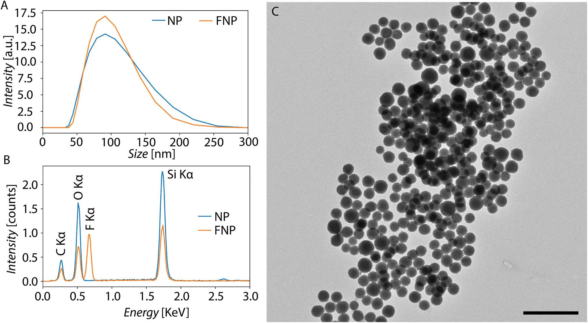 | ||
| Fig. 2 A) DLS data of 100 nm (F) NPs. (B): EDX spectrum of (F) NPs. (C): TEM images of FNPs (scale bar 500 nm). | ||
2.2 Fluorophore retention and leakage
| Dye | DPBS | DMEM | MiliQ | Tris | Charge (pH: 7.4) |
|---|---|---|---|---|---|
| Rhod 6 G | 5.65 | 5.65 | 5.64 | 5.65 | 0 |
| NR | 4.62 | 4.62 | 4.62 | 4.62 | 0 |
| Rhod101 | 4.18 | 4.07 | −2.85 | −0.13 | 0 |
| RhodB | 3.01 | 2.89 | −4.29 | −1.39 | 0 |
| EMA | 2.71 | 2.61 | 0.97 | 0.39 | −1 |
| Cy7 | 2.45 | 2.34 | −1.68 | 1.22 | −1 |
| Res | 0.63 | 0.63 | 0.63 | 0.63 | 0 |
| AZ | −0.31 | −0.31 | −0.29 | −0.31 | −1 |
| Sulford | −0.85 | −0.96 | −4.98 | −2.08 | −1 |
| Fl | −1.34 | −1.34 | −1.07 | −2.00 | −2 |
| Cy5 | −2.27 | −2.38 | −6.4 | −3.5 | −2 |
| DAPI | −3.24 | −3.46 | −7.93 | −5.5 | +2 |
| AF350 | −5.92 | −5.92 | −5.66 | −6.16 | −2 |
| Pyr | −6.33 | −6.33 | −6.31 | −6.34 | −3 |
| AF488 | −7.13 | −7.13 | −7.03 | −7.53 | −3 |
| AF568 | −7.20 | −7.31 | −13.64 | −11.6 | −3 |
 | ||
| Fig. 3 Comparison of dye partitioning from aqueous phase into oil phase (HFE 7500) containing RAN, Krytox or FNPs. Samples were compared with one-sided t-test assuming variance and normal distribution. Colours were given according to p-values green for p-value > 0.01 red for p-value < 0.01. Dyes were sorted based on the distribution coefficients in DPBS. | ||
For NR no significant enhancement of dye leakage was measured compared to the HFE samples, this results from the strong partitioning of the dye into the oil phase.42 If the majority of the dye already leaks in the pure HFE case, additional surfactant will not be able to induce any additional leakage.
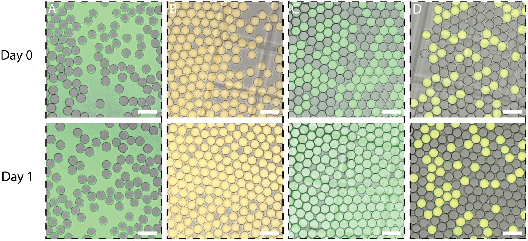 | ||
| Fig. 4 Examples of the 4 different leakage categories. (A) Category 1: RhodB in DPBS with Krytox, strong leakage of dye. (B) Category 2: Rhod6G in DPBS with RAN, retention of the dye but strong cross-talk. (C) Category 3: Fl in DPBS with Krytox, retention of the dye but cross-talk over time. (D) Category 4: Cy5 in DPBS with RAN, retention of the dye, no cross-talk after 1 day (100 μM scale bar). | ||
A colour-coded overview of the leakage categories in which all the different conditions tested were classified is presented in Fig. 5. A first important observation that can be made from these results is that cross-talk was minimally influenced by the buffer solutions in which the dyes were dissolved, in line with previous observations by Janiesch et al.23 Another clear trend that can be inferred is that, for all these conditions, the more hydrophobic a dye was, the more leakage observed.
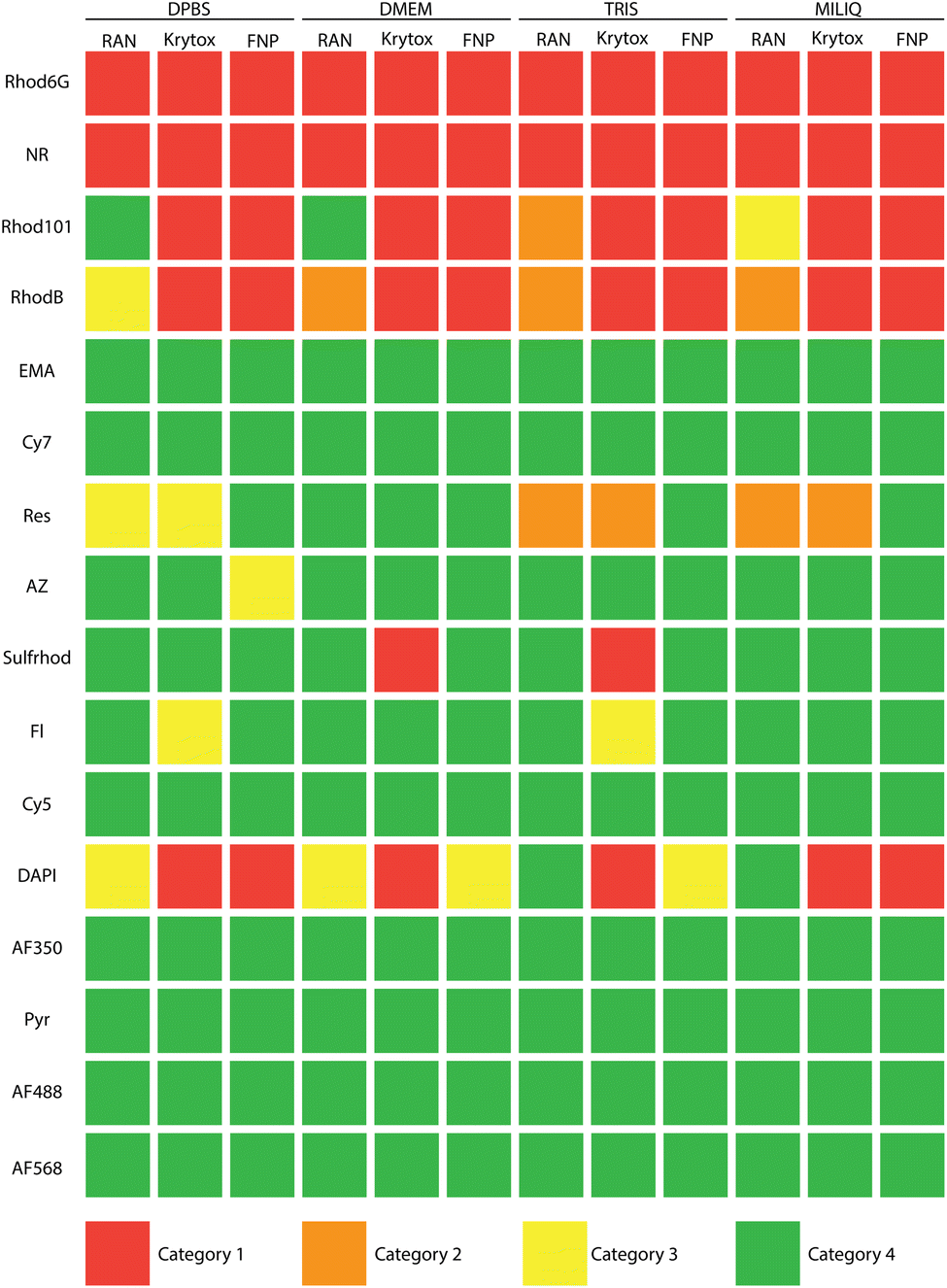 | ||
| Fig. 5 Colour coded overview of leakage between droplet. Dyes are sorted based on distribution coefficient in DPBS (at the top the most hydrophobic dyes and at the bottom the more hydrophilic ones). | ||
Perhaps the most striking result from our experiments is that, while it was previously reported that FNPs in fluorinated Pickering emulsions create a protective shell around droplets that effectively deters leakage,25 our observations clearly contradict these claims: our FNP-stabilised droplets indeed exhibited significant degrees of leakage. This phenomenon was particularly pronounced for highly hydrophobic dyes (typically also neutrally charged), which in all cases surpassed the leakage levels observed with commercially-available RAN surfactant. There was a single, notable exception to this trend, namely for the Res dye, which leaked out from RAN- and Krytox-stabilised droplets but not from FNP-stabilised samples. This exceptional behaviour might be the result of the neutral charge of resorufin, in combination with its intermediate distribution coefficient and small size. As explained in the previous section, leakage from FNP-stabilised droplets can be explained by a combination of dye-particle interactions with a consequent change in the surface energy of these FNPs.
The leakage of DAPI from Krytox- and FNP-stabilised droplets possibly results from the electrostatic interaction between the Krytox and FNPs charged groups and the many amine groups present in the DAPI molecules, providing it with a positive charge. Additionally,23 showed that low molecular dyes with planar structures can cross the droplet barrier more easily, which could potentially further explain the higher leakage observed for the DAPI, Fl and Res dyes. The UV-vis plate experiments and the observation of leakage in droplets do show some difference. This can be attributed due to the higher sensitivity of the plate assay compared to the droplet experiments.
Finally, it also needs to be noted that the low leakage of RAN-stabilised droplets could be partially explained by the use of BSA in our inner aqueous media, which was previously shown to reduce leakage by adsorbing to the o/w interface.42 We chose to perform these experiments with BSA since BSA was essential for the rapid stabilisation of droplets with FNPs. To allow comparison the same buffer conditions were used for Krytox and RAN, although here BSA was not necessary for droplet stabilisation.
2.3 On chip leakage
To assess the dynamics of the leakage process, three different droplet systems, each stabilised by all three assessed reagents, were generated and immediately imaged with a fluorescence high-speed camera. The three systems encapsulated: a well retained dye (AF488), a moderately-leaking dye (sulford) and a strongly-leaking dye (Rhod6G) respectively. Fig. 6 illustrates the results of these experiments. In case of the AF488 dye, no leakage could be observed on-chip for any of the stabilising agents, as expected. For sulford, some leakage was already noticeable at this early stage when the Krytox surfactant was used as a stabiliser. For the strongly-leaking Rhod6G dye, this leakage was immediately observed already from the point of droplet production in all conditions. Notably, in the FNP condition this early leakage was less pronounced compared to the two surfactants, which is likely the result of the lower mobility of the relatively larger FNPs. | ||
| Fig. 6 On chip droplet production for three different dyes and three different surfactant, imaged with Nikon Ti2 (100 μM scale bar). | ||
2.4 Droplet stability
Another claim that has traditionally been made is that FNP-stabilised emulsions are more stable (less prone to collapse) respect to surfactants.41 To verify if this feature also holds for FNP-stabilised droplets, these systems were produced and compared to surfactant-stabilised droplets after subjecting them to different environmental conditions. Concretely, five samples of droplets stabilised by the three different reagents were prepared and subsequently exposed to a PCR-like thermocycling process (as described in the Methods section), upon which they were imaged to assess their stability. Furthermore, the same conditions and amount of repeats were used to test droplets for long-term stability upon storing them under three different conditions for a period of 14 days: in the fridge (4 °C), at room temperature (21 °C) and in an incubator (37 °C).The assessment of droplet stability upon PCR-like thermocycling is presented in terms of the evolution of the coefficient of variance (CV) values of the droplets' diameter before and after this treatment, and is depicted in Fig. 7. The most striking outcome of this process occurred in droplets stabilised with Krytox, which acquired irregular, non-circular shapes (and were, therefore, not analysed for their diameter and CV after the thermocycling process). Remarkably, these droplets were still quite stable: no fusion events were observed during the imaging process when droplets collided with each other. The effects of temperature on surfactant solutions were previously studied with molecular dynamics simulations, which concluded that as the temperature increases, thermophoresis of water molecules causes the hydrogen bonding between water and surfactant molecules to fracture and reconnect.43,44 As mentioned previously, Krytox is composed of a PFPE chain functionalized with a carboxylic acid group.1,20–22 To explain these results, we hypothesise that the carboxylic acid groups of Krytox molecules are fracturing their hydrogen bonds with water molecules and reforming them with carboxylic acids of neighbouring surfactant molecules, a phenomenon that has previously been observed in carboxylated PFPEs.45 In these interfacial conditions, this reaction possibly leads to the formation of some form of hydrogen-bonded (fluoro)organic framework46 at the droplet interface that behaves more like a gel and, therefore, can sustain deformations and support the non-circular shape of such droplets.
 | ||
| Fig. 7 A) Boxplot of CV values of droplet diameters measured before and after a PCR-like thermocycling process. (B) Representative images of the same droplets (scale bar 100 μM). | ||
For the other two stabilisation systems exposed to a PCR-like thermocycling, the original droplet size was around 60 μM with a CV below 5%. After thermocycling, the CV of RAN-stabilised droplets became three times larger, indicating that a significant portion of the droplets stabilised with this reagent fused under these conditions. On the other hand, FNP-stabilised droplets remained relatively stable with only a limited increase in their CV as was shown in previous research.47 The lower stability of RAN droplets can be attributed to the thermoresponsive nature of the PEG molecules in this triblock copolymer, which potentially destabilises droplets during temperature changes.48–50 Additionally, the production of RAN does not result in a perfectly pure product, with traces of precursors, ionically-coupled surfactant and diblock copolymers still present. As previously suggested, this small amount of contaminating species might decrease the stability of RAN droplets.17,50
With regards to the long-term stability upon storage in different conditions, as illustrated by the CV values of the diameters of droplets (see Fig. 8), these always increased over time for RAN-stabilised droplets but for Krytox-stabilised droplets a CV increase was only seen after storage in the incubator. Conversely, for FNP-stabilised droplets, CV values remained constant in all storage conditions.
 | ||
| Fig. 8 Long term stability of droplets stabilized by different reagents under three different storage conditions: in the fridge, at room temperature and in an incubator. CV values and standard deviations of droplet diameters are plotted over a time period of two weeks. | ||
From the results of the above treatment and storage conditions, we can conclude that FNP-stabilised droplets have a superior stability compared to surfactant-stabilised droplets. This can be explained by the higher energetic stability of the particles at the droplet interface.41
2.5 Droplet production
In order to assess the versatility of the different stabilising reagents tested, different microfluidic droplet production strategies were tested (see Methods section) and their effectiveness in producing stable, monodisperse droplet populations was assessed. This assessment is important since robust stabilisation of droplets with FNPs has been reported to occur more slowly than with surfactants, which is problematic for the adequate performance of droplet-based microfluidic assays.For all cases the aqueous phase consisted of DPBS with 5 mg mL−1 BSA. As it was shown in previous papers, BSA promotes a more rapid stabilisation of droplets.30 Alternatively, a long serpentine channel could have been added to the end of the design to specifically allow FNPs sufficient time to adsorb at the droplet interface. We did not make use of this strategy since for the creation of small droplets this results in a large increase in hydraulic resistance and the consequent increase in pressure to drive flow usually leads to the delamination of the PDMS chip from its sealing glass substrate and failure of the device.
Resulting graphs for the three different flow focusing designs are plotted in Fig. 9. For the 20 μM flow focusing designs, Krytox- and RAN-stabilised droplet production behaved in a similar fashion. Similar flow rate ratios resulted in a similar droplet size. The FNP-stabilised droplets tended to be smaller for design 1 but in case of the other two designs droplet size was similar to that of the droplets stabilised by surfactants. In all of the above cases, the standard deviations are comparable, indicating a robust production of monodisperse and stable droplets in all systems.
 | ||
| Fig. 9 Droplet size in function of the flow rate ratio (flow rate of the oil phase/flow rate of the aqueous phase) for three different flow focusing designs with 2% Krytox, 2% RAN and FNPs. | ||
For the 10 μM designs, production of RAN- and Krytox-stabilised droplets remained again relatively similar. For FNP stabiliser, though, droplets were slightly larger for the second and the third designs. In all cases the standard deviation are slightly higher compared to the 20 μM design, which could arise as a result of a higher sensitivity to pressure fluctuations of the pumps for devices with smaller channel sizes.
In the T-junction device, droplets could be produced for all three droplet stabilisers. The trend shows that the higher the flow rate ratio was, the smaller the droplets were, starting at around 35 μM for a flow rate ratio of 1 decreasing to around 20 μM for a flow rate ratio of 8, this can be expected upon inspection of the literature.51 No significant differences between droplet size and monodispersity, as well as stability, could be observed for the three different stabilisers after these experiments.
With the two different step-emulsification designs droplets could be produced with 45 and 15 μM in diameter (see Fig. 10). Interestingly, when BSA was added to DPBS, no droplets could be produced with FNPs as stabilising agents. In these conditions, the droplets did not pinch-off as expected and only very large, polydisperse droplets were formed. When utilising MiliQ water without BSA, though, droplet pinch-off did effectively happen. This indicates that the compounds present in the aqueous solution that one attempts to encapsulate in droplets can critically influence droplet formation when FNPs are used as droplet stabilisers.
 | ||
| Fig. 10 Droplet size in function of the flow rate ratio (flow rate of the oil phase/flow rate of the aqueous phase) for three different flow focusing designs with 2% Krytox, 2% RAN and FNPs. | ||
The diverse influence that BSA exerts on the production of droplets in these different droplet-generation systems can be explained due to the attraction between the positively-charged amino acids in BSA and the negative charges on these silica-based FNPs. For the flow focusing designs (if no long serpentine channel is present) BSA may play an essential role in promoting a rapid particle accumulation (i.e. beyond their diffusion-limited rate) at the droplet interface. Additionally, hydrophobic–hydrophobic interaction between the fluorocarbon chains and the BSA molecules could also facilitate this more rapid stabilisation.30 In the case of the step emulsification devices, since droplet formation is a relatively slower process as it is not dependant on high shear energy as in flow focusing devices,52 there appears to be no need for the use of a stabilisation enhancer. In these circumstances, BSA seemed to actually negatively impact droplet formation, possibly by affecting the droplet necking and pinch-off processes due to its exertion of dynamic, localised changes in surface tension, which is a critical parameter regulating droplet formation in these systems.52–54
Finally, in the device combining flow focusing with step emulsification, droplet production resulted in droplets of about 10 μM in size for all three different droplet stabilisers. Here, solutions both with and without BSA could be utilised without any detrimental effects in droplet monodispersity and stability.
In general droplet size and polydispersity was very similar for all the different stabilisers. For the use of FNPs for droplet stabilisation, though, it is important to highlight some important differences with respect to surfactants. During our experiments, we noticed that a good modification of the surface of the devices (i.e., with fluorinated silanes) is of paramount importance for all designs except for the step emulsification ones. In flow focusing chips that were silanised more than two days before droplet production, some of the droplets readily wetted parts of the channel where, presumable, the fluorosilane layer had become deteriorated. These wetting issues resulted in droplet fusion and splitting events that led to a final polydisperse droplet population. Secondly, FNPs aggregated when in direct contact with the silanising agent (probably due to the high reactivity of the silanising agent with silanol groups), resulting in channel obstruction. This could be avoided by immediately rinsing the devices with pure HFE 7500 upon finalisation of the silanisation treatment.
2.6 Cell adhesion
The adhesion of MCF-7 and MCF-10A cells to oil phases stabilised with 2% Krytox, 2% RAN and FNPs was investigated. Since the cell medium reacted to the Krytox-stabilised oil (Fig. S4†), we focus on oil phases stabilised with RAN and FNPs. First, as was performed by Pan et al.25 we investigated cellular adhesion in 96-well plates by first pipetting 200 μL of the oil phase in the plate, followed by adding 100 μL of cell suspension. As a control, non-stabilised HFE 7500 and 96-well plate for adherent cell culture were included. For both cell types, no cell adhesion was observed for oil stabilised with RAN surfactant, as only free-floating cells and mammosphere-like colonies could be observed (see Fig. 11). In contrast, for both cell types, cell adhesion was observed for both FNP-containing oil and HFE 7500. Similar to the results found by Pan et al.25 adhering cells as well as free-floating mammosphere-like cells were observed for FNP-stabilised oil. Pan et al. hypothesised that the FNPs form rigid-like structures for cells to adhere. Although this is one possible explanation, the observations of cell adhesion to non-stabilised HFE 7500 in our work and to HFE 7500 supplemented with the surfactant pentafluorobenzoyl chloride in previous research55 illustrate that additional mechanisms might be in play as well such as the formation of rigid protein films by adsorption of cell medium proteins to the FNP stabilised o/w interface.55,56 Therefore, further research on the nature of the interaction between the cells and the oil phases is required to elucidate the cellular adhesion mechanism to FNP stabilised oil. | ||
| Fig. 11 Cell adhesion investigated in 96 well plate for MCF-7 and MCF-10A cells on a tissue-culture treated plate, on HFE 7500, on HFE 7500 with RAN surfactant and with FNP after 48 h of incubation (scale bar 100 μM). | ||
In another study by Lin et al.31 it was observed that MCF-7 cells could adhere to the droplet border when encapsulated in droplets stabilised by FNPs. Given the observed adhesion in the plate-based experiment, both cell types were encapsulated in droplets of approximately 100 μM in diameter, which were stabilised by 2% Krytox, 2% RAN and FNPs (see Fig. 12). Once more, since there was an interaction between the cell medium and Krytox (ESI S4†), only results of RAN and FNP stabilised droplets are discussed. After an incubation of 24 h and 48 h, it was observed that when imaging droplets stabilised with RAN, all cells were in the same focal plane, while when imaging droplets stabilised with FNPs, cells were in different focal planes. Although these results indicate adhesion of the cells to the droplet edge, the typical morphology of spreading cells (i.e. when cells flatten and extend their membranes after adhering to a surface), could not be observed at the droplet interface, which might indicate that the adhesion is non-specific or that the adhesion does not result in spreading due to the high curvature of the droplets. Given the different results obtained here and in the work of Lin et al.31 where spreading was observed, future research is needed to investigate different parameters that might influence cellular adhesion to the FNP stabilised droplets, such as droplet size, FNP concentration, FNP fabrication, FNP characteristics, etc.
 | ||
| Fig. 12 Cells (MCF-7 and MCF-10A) encapsulated in microfluidic droplets stabilised by RAN surfactant and FNPs. Representative image after 24 h of incubation (scale bar 100 μM). | ||
3. Conclusion
In summary, our investigation show that despite the robust adsorption of FNPs at the droplet interface, the prevention of leakage remains challenging, particularly in the case of hydrophobic dyes. However, some specific dyes, such as resorufin, exhibit improved protection against leakage when stabilised by FNPs compared to RAN or Krytox. The experiments presented in this manuscript primarily focused on fluorophore leakage. Further investigations are necessary to explore the leakage of other hydrophobic compounds, such as antibiotics, as discussed in.4The process of droplet production exhibits strong similarity between FNPs, RAN, and Krytox for droplets generated by flow focusing. Initially we hypothesised that the slow diffusion of the particles to the droplet interface might prove problematic for droplet formation. However, this can be effectively addressed by the addition of BSA to the inner buffer solution, with the exception of step-emulsification devices, where BSA appears to impede the droplet pinch-off process. Encouragingly, FNPs demonstrate superior droplet stability under all examined storage conditions when compared to RAN and Krytox-stabilised droplets. Finally the adhesion of anchorage dependant cell is enhanced in a plate-based assay but could not be observed inside the droplets.
Looking ahead, further modifications of silica particles through silane chemistry hold the promise of providing droplets with more functionally tailored surfaces that can interact in specific manners with the droplet contents. Currently, the absence of commercially available fluorinated particles presents an opportunity for future advancements in the field, potentially leading to greater reproducibility and facilitating broader applications within microfluidics.
This study provides a comparison between FNPs, Krytox and RAN, comparing droplet leakage, cross-talk, stability, production and the adhesion of anchorage dependant cells. The findings shown in this manuscript can help in the choice of the most suitable surfactant for the right applications, driving further microfluidic innovations.
Conflicts of interest
There are no conflicts to declare.Acknowledgements
The authors would like to acknowledge the help of the VIB bioimaging core for assisting with TEM imaging, and the help of Emiel De Rieck for assisting with cell culture. This research has received funding from the Research Foundation Flanders with grant No. 1S43521N. Additionally this work received funding from the European Union's Horizon Europe research and innovation programme EIC grant agreement No. 101095606 (PCR-4-ALL) and EIC grant agreement No. 101046894 (SynEry). Views and opinions expressed are however those of the author(s) only and do not necessarily reflect those of the European Union or the granting authority European Union's Horizon Europe research and innovation programme. Neither the European Union nor the granting authority can be held responsible for them.Notes and references
- P. Gruner, B. Riechers, L. A. Chacòn Orellana, Q. Brosseau, F. Maes, T. Beneyton, D. Pekin and J. C. Baret, Curr. Opin. Colloid Interface Sci., 2015, 20, 183–191 CrossRef CAS.
- A. Kulesa, J. Kehe, J. E. Hurtado, P. Tawde and P. C. Blainey, Proc. Natl. Acad. Sci. U. S. A., 2018, 115, 6685–6690 CrossRef PubMed.
- O. J. Miller, A. E. Harrak, T. Mangeat, J.-C. Baret, L. Frenz, B. E. Debs, E. Mayot, M. L. Samuels, E. K. Rooney, P. Dieu, M. Galvan, D. R. Link and A. D. Griffiths, Proc. Natl. Acad. Sci. U. S. A., 2012, 109, 378–383 CrossRef CAS PubMed.
- A. Ruszczak, P. Jankowski, S. K. Vasantham, O. Scheler and P. Garstecki, Anal. Chem., 2023, 95, 1574–1581 CAS.
- J. J. Agresti, E. Antipov, A. R. Abate, K. Ahn, A. C. Rowat, J.-C. Baret, M. Marquez, A. M. Klibanov, A. D. Griffiths and D. A. Weitz, Proc. Natl. Acad. Sci. U. S. A., 2010, 107, 4004–4009 CrossRef CAS PubMed.
- H. N. Joensson and H. Andersson Svahn, Angew. Chem., Int. Ed. Engl., 2012, 51, 12176–12192 CrossRef CAS PubMed.
- K. Matuła, F. Rivello and W. T. S. Huck, Adv. Biosyst., 2020, 4, 1900188 CrossRef PubMed.
- J.-C. Baret, Lab Chip, 2012, 12, 422–433 RSC.
- P. Zhu and L. Wang, Lab Chip, 2017, 17, 34–75 RSC.
- L. Amirifar, M. Besanjideh, R. Nasiri, A. Shamloo, F. Nasrollahi, N. R. de Barros, E. Davoodi, A. Erdem, M. Mahmoodi, V. Hosseini, H. Montazerian, J. Jahangiry, M. A. Darabi, R. Haghniaz, M. R. Dokmeci, N. Annabi, S. Ahadian and A. Khademhosseini, Biofabrication, 2022, 14(2), 022001 CrossRef PubMed.
- D. O'Hagan, Chem. Soc. Rev., 2008, 37, 308–319 RSC.
- D. M. Lemal, J. Org. Chem., 2004, 69, 1–11 CrossRef CAS PubMed.
- R. L. Scott, J. Am. Chem. Soc., 1948, 70, 4090–4093 CrossRef CAS PubMed.
- J. Clausell-Tormos, D. Lieber, J.-C. Baret, A. El-Harrak, O. J. Miller, L. Frenz, J. Blouwolff, K. J. Humphry, S. Köster, H. Duan, C. Holtze, D. A. Weitz, A. D. Griffiths and C. A. Merten, Chem. Biol., 2008, 15, 427–437 CrossRef CAS PubMed.
- J. N. Lee, C. Park and G. M. Whitesides, Anal. Chem., 2003, 75, 6544–6554 CrossRef CAS PubMed.
- R. Scanga, R. Nassar, B. Miller, H. Gang, X. Li and J. B. Hutchison, Polym. Prepr., 2009, 50, 148 CAS.
- C. Holtze, A. C. Rowat, J. J. Agresti, J. B. Hutchison, F. E. Angilè, C. H. J. Schmitz, S. Köster, H. Duan, K. J. Humphry, R. A. Scanga, J. S. Johnson, D. Pisignano and D. A. Weitz, Lab Chip, 2008, 8, 1632–1639 RSC.
- D. J. Holt, R. J. Payne, W. Y. Chow and C. Abell, J. Colloid Interface Sci., 2010, 350, 205–211 CrossRef CAS PubMed.
- W. L. Matochko, S. Ng, M. R. Jafari, J. Romaniuk, S. K. Y. Tang and R. Derda, Methods, 2012, 58, 18–27 CrossRef CAS PubMed.
- T. D. Rane, H. C. Zec and T.-H. Wang, Anal. Chem., 2015, 87, 1950–1956 CrossRef CAS PubMed.
- C. M. Ackerman, C. Myhrvold, S. G. Thakku, C. A. Freije, H. C. Metsky, D. K. Yang, S. H. Ye, C. K. Boehm, T.-S. F. Kosoko-Thoroddsen, J. Kehe, T. G. Nguyen, A. Carter, A. Kulesa, J. R. Barnes, V. G. Dugan, D. T. Hung, P. C. Blainey and P. C. Sabeti, Nature, 2020, 582, 277–282 CrossRef CAS PubMed.
- K. F. Tjhung, S. Burnham, H. Anany, M. W. Griffiths and R. Derda, Anal. Chem., 2014, 86, 5642–5648 CrossRef CAS PubMed.
- J. W. Janiesch, M. Weiss, G. Kannenberg, J. Hannabuss, T. Surrey, I. Platzman and J. P. Spatz, Anal. Chem., 2015, 87, 2063–2067 CrossRef CAS PubMed.
- Y. Skhiri, P. Gruner, B. Semin, Q. Brosseau, D. Pekin, L. Mazutis, V. Goust, F. Kleinschmidt, A. El Harrak, J. B. Hutchison, E. Mayot, J.-F. Bartolo, A. D. Griffiths, V. Taly and J.-C. Baret, Soft Matter, 2012, 8, 10618–10627 RSC.
- M. Pan, L. Rosenfeld, M. Kim and S. K. Tang, 18th International Conference on Miniaturized Systems for Chemistry and Life Sciences, MicroTAS 2014, 2014, pp. 76–78 Search PubMed.
- M. Pan, F. Lyu and S. K. Y. Tang, Anal. Chem., 2015, 87, 7938–7943 CrossRef CAS PubMed.
- M. Pan, M. Kim, L. Blauch and S. K. Tang, RSC Adv., 2016, 6, 39926–39932 RSC.
- M. Pan, F. Lyu and S. K. Tang, Anal. Methods, 2017, 9, 4622–4629 RSC.
- Y. Chevalier and M.-A. Bolzinger, Colloids Surf., A, 2013, 439, 23–34 CrossRef CAS.
- J. Liu, X. Lyu, Z. Zhou, L. Yang, J. Zeng, Y. Yang, Z. Zhao, R. Chen, X. Tong, J. Li, H. Liu and Y. Zou, Appl. Mater. Interfaces, 2023, 15(13), 17324–17334 CrossRef CAS PubMed.
- X. Lin, W. Qiu, G. D. Suarez and S. Nagl, Extracellular pH Monitoring of Live Single Cells in Microdroplets Using Dual-Labelled Fluorinated Silica Nanoparticles and Time-Domain Dual Lifetime Referencing, 2022 Search PubMed.
- L. A. ChaconOrellana and J.-C. Baret, ChemSystemsChem, 2019, 1, 16–24 CrossRef CAS.
- V. Mahalingam, S. Onclin, M. Péter, B. J. Ravoo, J. Huskens and D. N. Reinhoudt, Langmuir, 2004, 20, 11756–11762 CrossRef CAS PubMed.
- Kayaku Advanced Materials, SU82002, https://kayakuam.com/wp-content/uploads/2019/09/SU-82000DataSheet2000_5thru2015Ver4.pdf Search PubMed.
- Kayaku Advance Materials, SU82005-2015, https://kayakuam.com/wp-content/uploads/2019/09/SU-82000DataSheet2000_5thru2015Ver4.pdf Search PubMed.
- Kayaku Advanced Materials, SU82025-2075, https://kayakuam.com/wp-content/uploads/2019/09/SU-82000DataSheet2025thru2075Ver4-3.pdf Search PubMed.
- P. Gruner, B. Riechers, B. Semin, J. Lim, A. Johnston, K. Short and J.-C. Baret, Nat. Commun., 2016, 7, 10392 CrossRef CAS PubMed.
- C. J. DeJournette, J. Kim, H. Medlen, X. Li, L. J. Vincent and C. J. Easley, Anal. Chem., 2013, 85, 10556–10564 CrossRef CAS PubMed.
- A. M. Khan, F. Shafiq, S. A. Khan, S. Ali, B. Ismail, A. S. Hakeem, A. Rahdar, M. F. Nazar, M. Sayed and A. R. Khan, J. Mol. Liq., 2019, 274, 673–680 CrossRef CAS.
- J. Mecinović, P. W. Snyder, K. A. Mirica, S. Bai, E. T. Mack, R. L. Kwant, D. T. Moustakas, A. Héroux and G. M. Whitesides, J. Am. Chem. Soc., 2011, 133, 14017–14026 CrossRef PubMed.
- J. Wu and G.-H. Ma, Small, 2016, 12, 4633–4648 CrossRef CAS PubMed.
- F. Courtois, L. F. Olguin, G. Whyte, A. B. Theberge, W. T. S. Huck, F. Hollfelder and C. Abell, Anal. Chem., 2009, 81, 3008–3016 CrossRef CAS PubMed.
- P. Feng and L. Wang, J. Phys.: Conf. Ser., 2022, 2194, 012037 CrossRef.
- A. A. Ivanova, A. N. Cheremisin, A. Barifcani, S. Iglauer and C. Phan, J. Mol. Liq., 2020, 299, 112104 CrossRef CAS.
- V. Doan, R. Köppe and P. H. Kasai, J. Am. Chem. Soc., 1997, 119, 9810–9815 CrossRef CAS.
- P. Li, M. R. Ryder and J. F. Stoddart, Accounts Mater. Res., 2020, 1, 77–87 CrossRef CAS.
- K. Yin, X. Zeng, W. Liu, Y. Xue, X. Li, W. Wang, Y. Song, Z. Zhu and C. Yang, Anal. Chem., 2019, 91, 6003–6011 CrossRef CAS PubMed.
- N. Kameta, J. Dong and H. Yui, Small, 2018, 14, 1800030 CrossRef PubMed.
- N. Badi, Prog. Polym. Sci., 2017, 66, 54–79 CrossRef CAS.
- M. S. Chowdhury, W. Zheng, S. Kumari, J. Heyman, X. Zhang, P. Dey, D. A. Weitz and R. Haag, Nat. Commun., 2019, 10, 4546 CrossRef PubMed.
- S. K. Jena, T. Srivastava, S. S. Bahga and S. Kondaraju, Phys. Fluids, 2023, 35, 22107 CrossRef CAS.
- L. Liu, N. Xiang, Z. Ni, X. Huang, J. Zheng, Y. Wang and X. Zhang, Biotechniques, 2020, 68, 114–116 CrossRef CAS PubMed.
- D. R. Absolom, C. J. Van Oss, W. Zingg and A. W. Neumann, Biochim. Biophys. Acta, 1981, 670, 74–78 CrossRef CAS PubMed.
- M. Campana, S. L. Hosking, J. T. Petkov, I. M. Tucker, J. R. P. Webster, A. Zarbakhsh and J. R. Lu, Langmuir, 2015, 31, 5614–5622 CrossRef CAS PubMed.
- D. Kong, K. D. Q. Nguyen, W. Megone, L. Peng and J. E. Gautrot, Faraday Discuss., 2017, 204, 367–381 RSC.
- C. R. Keese and I. Giaever, Proc. Natl. Acad. Sci. U. S. A., 1983, 80, 5622–5626 CrossRef CAS PubMed.
Footnote |
| † Electronic supplementary information (ESI) available. See DOI: https://doi.org/10.1039/d4ra04298k |
| This journal is © The Royal Society of Chemistry 2024 |