
 Open Access Article
 This Open Access Article is licensed under a
 Creative Commons Attribution 3.0 Unported Licence
Cycling of potassium–carbonate co-substituted hydroxyapatite compositions for improved carbon dioxide capture at 500 °C†
Duncan A.
Nowicki
 *a,
Iain R.
Gibson
ab and
Janet M. S.
Skakle
ac
*a,
Iain R.
Gibson
ab and
Janet M. S.
Skakle
ac
aDepartment of Chemistry, University of Aberdeen, Meston Walk, Aberdeen AB24 3UE, UK. E-mail: duncan.nowicki@gmail.com; i.r.gibson@abdn.ac.uk; j.skakle@abdn.ac.uk
bInstitute of Medical Sciences, University of Aberdeen, Foresterhill, Aberdeen AB25 2ZD, UK
cDepartment of Physics, University of Aberdeen, Meston Walk, Aberdeen AB24 3UE, UK
First published on 22nd November 2023
Abstract
There is an immediate need to reduce CO2 emissions if the impacts of climate change are to be mitigated. Whilst carbon capture & storage offers such a route, costs associated with this technology necessitate that more efficient means of capture be developed—including studying materials that may have improved performance and/or end-use application as functional materials post-capture. Stoichiometric hydroxyapatite and potassium–carbonate co-substituted apatites were subjected to carbonation–regeneration cycles at 500 °C to explore their applicability for carbon capture, with chemical characterisation performed after each carbonation/regeneration. The CO2 carrying capacity increased alongside the degree of co-substitution; the material with the highest as-prepared potassium/carbonate content exhibited a carrying capacity of 0.57 mmol g−1 sorbent. This was more than seven times that of stoichiometric hydroxyapatite (0.08 mmol g−1 sorbent) and is the first demonstration showing that the CO2 carrying capacity can be increased via ionic substitution mechanisms. It was hypothesised that this improved performance was due to co-substitution having generated additional structural sites for interchange with CO2. In an extended study, the CO2 carrying capacity of one composition was observed to improve following an initial drop after the first cycle. This is significant when compared to calcium oxide, whose reactivity towards CO2 declined by 42% between the first and second cycles alone. FTIR spectroscopy suggested that the apatite material functioned by way of the simultaneous substitution of carbonate ions onto hydroxyl and phosphate sites during carbonation followed by the subsequent loss of these ions when the material was heated in air. Data from this study supports the concept that these materials could play a role as CO2 sorbents for industrial carbon capture and justifies further studies in more complex systems that could evaluate real-world application.
1. Introduction
The Intergovernmental Panel on Climate Change (IPCC) has projected that if current trends were to continue unabated, greenhouse gases such as CO2 could become so concentrated in the atmosphere that by the year 2100 the global mean surface temperature of the Earth could be more than 4 °C warmer than it was during the pre-industrial era. This would greatly disrupt the Earth's climate system1 and therefore it is essential that drastic action is taken to reduce the magnitude of anthropogenic greenhouse gas emissions.Fossil fuel power stations represent one of the largest sources of anthropogenic carbon dioxide emissions.2 These applications combust fossil fuels to produce electrical energy, and emit CO2 as part of the flue gas mixture. Whilst the ideal solution would be to immediately replace these installations with alternatives like solar and wind power, such technologies are not yet in a position to fulfil this role.3 Therefore, carbon capture & storage (CCS)—the process of capturing, transporting and permanently storing CO2 in a site such as a geological formation or the ocean—is necessary to reduce the emission of CO2. At present however, the additional costs associated with installation and operation inhibit the wide-scale deployment of CCS in fossil fuel power stations2 and although incentive schemes have been introduced there is still a need to improve the foundational economics.
In particular, improved means of CO2 capture are required. Chemical absorption of CO2 with organic solvents is currently the most mature capture technique, having been successfully applied on a small scale.4 Here, CO2 is absorbed by an aqueous amine solution, with this CO2-rich solution then heated at 100–200 °C to release the captured CO2 and regenerate the absorbent for further capture. Although this amine scrubbing technique is well understood, there are significant inherent drawbacks: (i) the amine solution is typically quite dilute and regeneration thus incurs a large energy penalty; (ii) improper disposal of process waste can cause environmental damage; and (iii) several common amines are corrosive to process equipment.5,6
In recent years, solid sorbents have received a great deal of attention. These materials separate CO2via adsorption processes and possess several advantages over aqueous amine sorbents. For example, solid sorbents can be used over a wider temperature range, can usually be disposed of without excessive environmental precautions and typically require less energy for sorbent regeneration.7 Nakagawa and Ohashi8 observed that the ceramic lithium zirconate (Li2ZrO3) reacts with CO2 to form lithium carbonate (Li2CO3) at 450–550 °C and that this reaction could be reversed at temperatures above 650 °C. Whilst this material has a large theoretical CO2 carrying capacity (6.53 mmol of CO2 per gram of sorbent), slow CO2 adsorption kinetics limit its practical application.8 Similarly, lithium orthosilicate (Li4SiO4) can adsorb CO2 in the temperature range 450–600 °C and desorb at temperatures above 700 °C. Not only does this material possess a larger theoretical CO2 carrying capacity (8.34 mmol g−1 sorbent) than lithium zirconate, it can also adsorb CO2 at a faster rate than Li2ZrO3;9 Kato et al.10 reported that Li4SiO4 adsorbed CO2 at 500 °C approximately thirty times faster than lithium zirconate even in low CO2 concentrations. Calcium oxide is probably the most widely studied solid sorbent for carbon capture at approximately 600–950 °C.11 Although there are several advantages inherent to CaO including a large theoretical CO2 carrying capacity (17.8 mmol g−1 sorbent) and a low cost,12 its ability to adsorb CO2 tends to decrease rapidly with multi-cycling. It has been reported that the sorbent's conversion will decrease dramatically in the first twenty cycles and eventually settle to 7–8% of its original value after ∼50 cycles.13 This loss of reactivity has been attributed to sintering of the sorbent, primarily during regeneration, which reduces porosity and thus the surface area available for reaction.14,15 It is possible to reactivate spent sorbent,16–19 but this will complicate process design. From these mixed results, further research in this field is required.
Thanks in part to its relatively high thermal stability and the fact that CO2 can be incorporated onto both hydroxyl and phosphate sites as CO32− ions (termed A-type and B-type carbonate substitution respectively), the calcium phosphate hydroxyapatite (HA, Ca10(PO4)6(OH)2) has been posited as a potential high-temperature (>400 °C) solid CO2 sorbent. Landi et al.20 prepared porous hydroxyapatite macrogranules (with granule sizes ranging from 400–600 μm) and tested their potential for carbon capture by subjecting them to a number of carbonation–regeneration cycles at 900, 1000, 1100 and 1200 °C in a thermogravimetric analyser. Carbonation was performed in a 50/50 CO2/Ar atmosphere whilst regeneration was performed in pure Ar; each step used a flowrate of 40 ml min−1 and lasted for one hour. Before these experiments, the apatite macrogranules were calcined in argon at 850 °C. The authors reported that the macrogranules repeatedly adsorbed and desorbed CO2 at each investigated temperature, with the weight gain upon carbonation at 1000 °C (2.1–2.3%) greater than at 900, 1100 and 1200 °C, where gains of 0.8–1.4, 2.1 and 1.0% respectively were seen. However, the authors also observed that total conversion was achieved after one hour only at 1200 °C. In a similar study, Ojeda-Niño et al.21 investigated the utility of hydroxyapatite derived from red tilapia fish scales as a solid CO2 sorbent. 10 mg of the apatite material (particle size <200 μm) was subjected to 15 carbonation–regeneration cycles in a thermogravimetric analyser. A cycle consisted of fifteen minutes of carbonation at 650 °C in CO2 gas followed by ten minutes of regeneration at 800 °C in nitrogen. Both steps used a flowrate of 50 ml min−1 and a heating/cooling rate of 10 °C min−1. Prior to these cycles, the material was heated at 800 °C in N2 to ensure complete decarbonation. The authors reported that although the CO2 carrying capacity of the material was quite low (approximately 0.06–0.07 mmol g−1 sorbent), its reactivity was relatively stable over the 15 cycles. Whilst these are positive results, there are still significant gaps in the literature that must be filled.
This study explores for the first time the applicability of hydroxyapatite for carbon capture at 500 °C, as well as the influence of ionic substitution on sorbent performance, by subjecting stoichiometric hydroxyapatite and potassium–carbonate (K/CO3) co-substituted apatites to repeated carbonation–regeneration cycles. We hypothesised that substituting carbonate ions into the hydroxyapatite lattice would allow for larger CO2 carrying capacities to be achieved and so a short study was first performed which investigated the relation between the degree of potassium/carbonate co-substitution in the material and the CO2 carrying capacity over three carbonation–regeneration cycles. The obtained results were compared with calcium oxide tested under similar cycling conditions. Subsequently, one of the apatites was studied in more detail by extending the number of cycles to fifteen to gain a better understanding of the functionality and stability of the material during repeated cycling.
Room temperature aqueous precipitation reactions between calcium hydroxide, phosphoric acid and potassium carbonate, very similar to those of our previous work,22 were used to prepare the K/CO3 co-substituted hydroxyapatite compositions. This choice was motivated by several factors. Firstly, it allowed for single-phase apatites with high degrees (up to approximately 16.9 wt% CO32−) of carbonation to be prepared. Secondly, the flexibility of the process could allow for egg/mollusc shells to be used as the calcium source,25,26 offering an opportunity to upgrade these low-value food wastes into valuable products. Finally, with no impurities produced alongside the apatitic phase, spent sorbent could find application as a high-quality solid agricultural fertiliser23,24 without posing acute risks to the environment.
2. Materials and methods
2.1. Synthesis of samples
Stoichiometric HA and K/CO3 co-substituted apatites were synthesised at room temperature in ambient atmosphere by aqueous precipitation reaction. This reaction was adapted from an established precipitation route27 and involved adding a phosphoric acid (H3PO4) solution dropwise to an aqueous suspension of calcium hydroxide (Ca(OH)2) and potassium carbonate (K2CO3). Each synthesis produced ∼10 g of material. The quantities of the reactants were calculated in accordance with the design composition formula Ca10−xKx(PO4)6−x(CO3)x(OH)2, where x = 0 (i.e. stoichiometric HA), 0.5, 1.0, 2.0 and 2.5, and are presented in Table S1 of the attached ESI.† Larger design substitution values were not explored, as we observed that x = 2.5 was close to the substitution limit for this synthesis route,22 above which secondary impurity phases precipitated.A basic suspension was prepared by dissolving K2CO3 (≥99% assay, Sigma-Aldrich, UK), if appropriate, followed by dispersing Ca(OH)2 (98% assay, VWR, UK) in approximately 150 ml of distilled water. 30 ml of aqueous NH3 solution (30–33% NH3 in water, Honeywell, UK) was added to the x = 0 suspension to ensure that the pH did not fall below pH 9 upon the introduction of the H3PO4 solution and thus avoid the formation of calcium-deficient impurity phases.28,29 However, the high Ca/P molar ratio of the reactants meant that the pH of the other suspensions did not require adjusting with ammonia solution. The H3PO4 solution was then prepared by diluting phosphoric acid (85% solution in water, Merck, UK) with 150 ml of distilled water and was then poured into a dropping funnel. The H3PO4 solution was added dropwise to the basic suspension (which was continuously stirred using a magnetic stirrer to avoid the build-up of local acidic environments) over a period of about 2 hours. This long timescale also prevented any significant heat being produced through exothermic reaction. After the addition of the H3PO4 solution was complete, the reaction mixture was stirred for a further two hours and was then left to age unstirred overnight. The reaction mixture was filtered under vacuum, thoroughly rinsed with distilled water and the resultant filter-cake dried in air in an oven at 90 °C overnight. The dried filter cake was then ground to a fine powder using a mortar and pestle. Subsequently, the powder was subjected to a heat treatment in air to remove synthesis residuals such as absorbed water; this heat treatment did not markedly affect the chemical composition of samples. Aliquots (c. 0.5 g) were heated in air from ambient to 300 °C in a muffle furnace (Carbolite Gero Ltd, UK) at a heating rate of 5 °C min−1, held there for one hour and then cooled back to room temperature at the same rate. Powders obtained after this heat treatment were labelled ‘as-prepared’ or ‘AP’.
2.2. Carbonation–regeneration experiments
To assess their potential for carbon dioxide capture, the prepared materials were then subjected to carbonation–regeneration cycles. These cycles were split into discrete steps so a detailed understanding of the processes taking place could be obtained by characterising the materials at each interval (i.e. after each individual carbonation/regeneration). Carbonation was performed in a tube furnace (Carbolite Gero Ltd, UK) under a dry CO2 gas flow of approximately 0.5 dm3 per minute. Whilst they would never operate in pure CO2 in an industrial setting, the relative novelty of these materials for this application necessitated these studies be performed first in the abstract rather than a more ‘real-world’ scenario. Regeneration was achieved by heating the materials in static air in a muffle furnace (Carbolite Gero Ltd, UK). In each case, the temperature was ramped from ambient up to 500 °C at a rate of 5 °C min−1, held there for one hour and then cooled back to room temperature at the same rate. Aliquots were collected at each interval after the material had cooled. Calcium oxide (CaO) obtained from commercial ACS grade calcium carbonate (Sigma Aldrich, UK) was also subjected to several cycles, with carbonation and regeneration performed using the same apparatus. During carbonation however, the temperature in the furnace was ramped from room temperature up to 650 °C at 5 °C min−1, held there for five minutes and then cooled to ambient at the same rate. For regeneration, the temperature was ramped from ambient up to 900 °C at a rate of 5 °C min−1, held there for one hour and then cooled back to room temperature at the same rate. These temperatures were chosen based on previous studies of CaO for carbon capture.11,30,31 The commercial CaCO3 powder was first calcined in air for one hour at 900 °C to decompose the material to CaO.2.3. Sample characterisation
Powder X-ray diffraction (XRD) patterns were collected to assess the phase composition of samples using an X’Pert Pro diffractometer (PANalytical Ltd, UK), operating at 45 kV and 40 mA with Cu Kα radiation (λ = 1.5406 Å). Data were collected between 15–65° 2θ with a step size of 0.013° and a count time of 96 s per step. Crystalline phases present were identified by comparing obtained patterns with PDF files from the ICDD database. Average crystallite sizes of samples were calculated using the Scherrer equation, with the (002) reflection at approximately 25.8° 2θ and k = 0.9. A highly crystalline quartz standard with peak at ∼28.48° 2θ was used to compute the instrumental line broadening. Lattice parameters were determined by simple Rietveld refinement of collected XRD data using the PANalytical software package ‘HighScore Plus’.32 Refinements were carried out in the hexagonal space group P63/m, with the hydroxyapatite crystal structure reported by Sudarsanan and Young33 serving as the initial structural model. In each case, only the background function, scale factor, unit cell parameters and peak shape functions were refined. The carbonate contents of samples were determined using a LECO CS744 carbon/sulphur analyser (LECO Instruments UK Ltd, UK). For each sample, duplicate measurements were made and the mean value reported alongside the standard deviation. It was assumed that all of the carbon detected by the equipment existed as CO2, a reasonable assumption as the equipment flooded the combustion chamber with oxygen during operation and also passed the combustion products through an oxidation catalyst. FTIR spectra were obtained using a Diamond/ZnSe ATR attached to a Spectrum Two™ spectrometer (PerkinElmer, UK). Absorbance spectra were collected at a 2 cm−1 resolution between 4000 and 400 cm−1, averaging 7 scans per sample. Where applicable, XRD and FTIR data was normalised by dividing each value of the dataset by the sets maximum value. Peak deconvolution of the carbonate ν2 (890–845 cm−1) region of FTIR spectra was performed by fitting Gaussian distributions, based on peak assignment described elsewhere, using the Solver extension in Excel.34 A linear background was subtracted prior to deconvolution.3. Results and discussion
3.1. Influence of potassium/carbonate substitution on CO2 carrying capacity
Prior to the cycling experiments, each as-prepared material was characterised using XRD and FTIR spectroscopy and had their carbonate contents determined by combustion analysis. This revealed that each was a phase-pure apatite and suggested that the chemical compositions of the co-substituted apatites were very similar to those prepared in our previous work,22 despite the fact that NH4OH solution was not used for pH adjustment in the present study. For brevity, this analysis was included as part of the ESI† (Fig. S1, S2 & Table S2).X-ray diffraction patterns of the x = 2.5 material as-prepared and at each interval over the three carbonation–regeneration cycles are shown in Fig. 1. XRD patterns of each of the other materials (x = 0, 0.5, 1.0 and 2.0) are shown in Fig. S3–S6 (ESI†) respectively. The diffraction peaks in all these patterns could be indexed on the ICDD standard35 for hydroxyapatite, with no extraneous reflections attributable to crystalline impurity phases such as calcium oxide (CaO) or calcium carbonate (CaCO3) present. This indicated that neither carbonation nor regeneration at 500 °C resulted in phase decomposition of the apatites at any point over the course of these cycles. It was not surprising that carbonation did not give rise to any secondary phases, as we observed previously in similar samples22 that impurity phases were not produced when an as-prepared x = 2.5 sample was heated in dry CO2 at temperatures up to 600 °C.
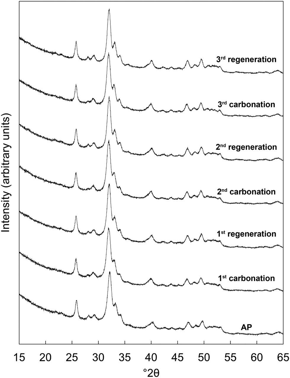 | ||
| Fig. 1 Normalised (Imax = 100) XRD patterns of the x = 2.5 apatite as-prepared (AP) and over three carbonation–regeneration cycles at 500 °C in dry CO2 and air respectively. | ||
Fig. 2 shows the measured carbonate content of each apatite material as-prepared and at each interval over the three cycles. Each was a functional reversible CO2 sorbent at 500 °C, with increases in the carbonate content of the materials apparent upon carbonation and decreases with regeneration. The CO2 carrying capacity (calculated from the results of Fig. 2 and shown in Table 1) increased proportionally to x; the apatite with the highest degree of K/CO3 co-substitution (x = 2.5) exhibited an average CO2 carrying capacity of 0.57 mmol g−1 sorbent, more than seven times larger than that seen for stoichiometric HA, x = 0 (0.08 mmol g−1 sorbent), and the greatest carrying capacity reported for such a material to date. Importantly, this is the first demonstration that the carrying capacity of these apatite materials can be improved via ionic substitution mechanisms. More broadly, the other K/CO3 co-substituted apatite compositions could still be effective for carbon capture despite their lower CO2 carrying capacities. For example, as they are likely to possess greater degrees of thermal stability than the x = 2.5 material, it is feasible that they could be good CO2 sorbents at slightly higher temperatures. It is well established that carbonate ions can substitute onto and be lost from both the hydroxyl and phosphate sites of HA during heating.36 Therefore, it seemed that the improved performance with increasing x was a result of the co-substitution of K+/CO32− ions having generated additional sites for interchange of carbon dioxide. Whilst this small number of cycles was not enough to be conclusive, it appeared that the carrying capacity of the materials was relatively constant after the first cycle, as was the case for stoichiometric HA in previous studies.20,21 The significance of these stable reactivities can be observed by contrasting the apatites with calcium oxide. Despite the higher CO2 carrying capacity (Table 1 and Fig. S7, ESI†), the reactivity of CaO with respect to CO2 declined by 42% between the first and second cycles and continued to diminish with further cycling. Another interesting observation is the fact that the x = 0 apatite only achieved a carbonate content of 2.57 wt%, far from that of a fully substituted A-type CHA of chemical composition Ca10(PO4)6CO3 (5.82 wt%). Whilst this was not surprising as temperatures of 900–1000 °C are typically required to prepare a fully-substituted A-type CHA,37–39 it was nevertheless interesting that CO2 was incorporated onto at most only 44% of the hydroxyl sites. This may also have been true for the other samples, but additional studies would be required to determine if this were so.
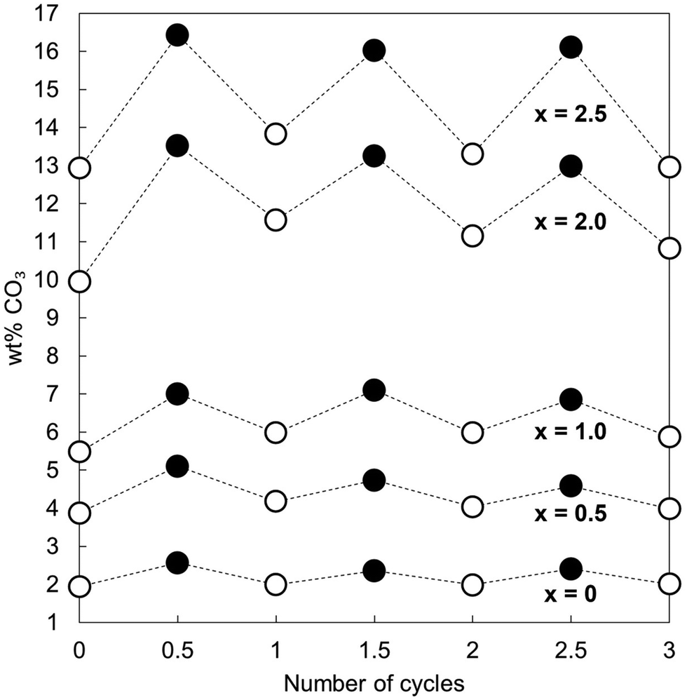 | ||
| Fig. 2 Measured carbonate content of each apatite material as-prepared (i.e. when the number of cycles = 0) and over three carbonation–regeneration cycles. Carbonated samples are represented by filled markers whilst as-prepared and samples heated in air are denoted using open markers. | ||
| Cycle | x = 0 | x = 0.5 | x = 1.0 | x = 2.0 | x = 2.5 | CaO |
|---|---|---|---|---|---|---|
| 1 | 0.11 | 0.22 | 0.27 | 0.69 | 0.70 | 17.01 |
| 2 | 0.06 | 0.10 | 0.20 | 0.33 | 0.44 | 9.83 |
| 3 | 0.07 | 0.10 | 0.16 | 0.36 | 0.56 | 6.67 |
| Average | 0.08 | 0.14 | 0.21 | 0.46 | 0.57 | 11.17 |
3.2 Extended study of 15 carbonation–regeneration cycles
Based on the initial results that showed that the x = 2.5 potassium/carbonate co-substituted apatite was the most promising of the studied materials, it was subjected to an extended study of 15 carbonation–regeneration cycles. Another batch of this composition was prepared for this larger study; characterisation of the as-prepared powder (x = 2.5 B) can be found in the ESI† alongside those described earlier (Fig. S1, S2 and Table S2).XRD patterns of the as-prepared apatite and at several points over the course of these 15 cycles are shown in Fig. 3. Each of these patterns was comparable to the ICDD standard35 for hydroxyapatite and therefore it is evident that the material remained as a phase-pure apatite even after being subjected to the extended number of cycles. The resolution of the three intense peaks between 30–35° 2θ improved with cycling, which might imply an increasing crystalline fraction.40 Analysis using the Scherrer equation (Table 2) did not show a marked increase in the size of the primary particles due to the low temperatures at which the material was heated, perhaps significant when one considers that the rapid loss of reactivity characteristic of CaO has been assigned to a large decrease in surface area from sintering of the sorbent.14,15,41 Disruption caused by the coronavirus pandemic meant that it was not possible to determine the textural characteristics of the apatite material over these cycles, a key limitation of this study as a sorbents viability for carbon capture is often very dependent on these features.42–44
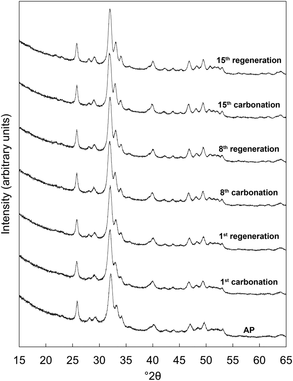 | ||
| Fig. 3 Normalised (Imax = 100) X-ray diffraction patterns of the x = 2.5 apatite as-prepared (AP) and at several intervals over 15 cycles at 500 °C in dry CO2 and air respectively. | ||
| Interval | AP | 1st car. | 1st reg. | 8th car. | 8th reg. | 15th car. | 15th reg. |
|---|---|---|---|---|---|---|---|
| τ (nm) | 20 ± 1 | 17 ± 1 | 19 ± 1 | 20 ± 1 | 20 ± 1 | 21 ± 1 | 20 ± 1 |
The carbonate content of the material as-prepared and at each interval over the 15 cycles is shown in Fig. 4 alongside the calculated CO2 carrying capacity. Rather than remain relatively constant following a significant drop after the first cycle as might have been expected from Table 1, the CO2 carrying capacity actually increased with repeated cycling (Fig. 4(B)), rising from a low of 0.37 mmol g−1 sorbent (cycle 2) to 0.54 mmol g−1 sorbent in the final cycle. It is worth noting that the average carrying capacity of this sample was 0.45 mmol g−1 sorbent, smaller than the value of 0.57 mmol g−1 sorbent seen for the x = 2.5 apatite in the initial study, Table 1. This was likely due to small differences in the composition of the two precipitate batches, an inherent characteristic of the aqueous precipitation synthesis route used in this study (Fig. S1, S2 and Table S2, ESI†). Although the carbonate content of the material upon both carbonation and regeneration decreased as the number of cycles to which the material was subjected increased, the decay in the CO32− content of the regenerated samples was much larger than that seen in the carbonated samples. Therefore, it would seem logical that this increased CO2 carrying capacity was primarily a result of the heat treatment in air resulting in a greater portion of available sites for reaction, whether those additional sites were hydroxyl, phosphate or a combination of both.
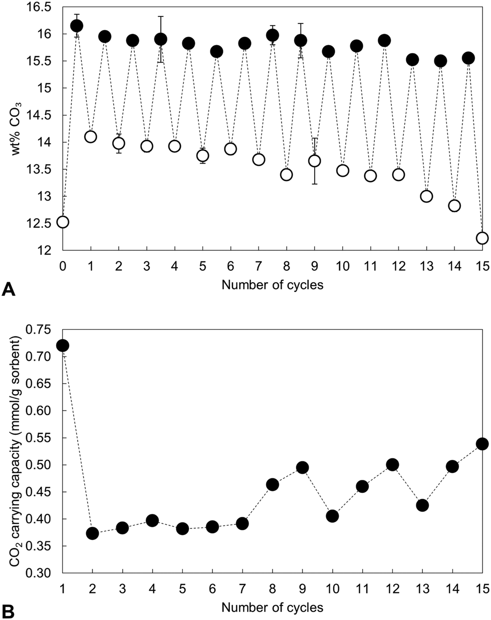 | ||
| Fig. 4 (A) Measured carbonate content of the x = 2.5 apatite as-prepared and over 15 cycles at 500 °C. Filled markers represent samples heated in dry CO2 whereas open markers denote samples heated in air. (B) The carrying capacity of the material over these cycles, defined as the quantity of CO2 absorbed during each carbonation. | ||
Nevertheless, over these cycles, the carrying capacity never again reached the initial value of 0.72 mmol g−1 sorbent, due to an inability to fully regenerate the sorbent. Carbonate release from HA during heating is known to increase with increasing temperature and so various carbonated samples were heated in air at 600 °C as a regeneration step to investigate whether this would change the carrying capacity. The XRD patterns presented in Fig. 5 however demonstrated that this higher regeneration temperature produced impurity phases of calcium oxide and/or calcite. It should be noted that in these experiments only the last regeneration was performed at 600 °C, with each of the previous steps performed at 500 °C. For example, the ‘6th cycle’ sample shown in Fig. 5 was cycled 5 times at 500 °C, carbonated at 500 °C and then regenerated at 600 °C. Even so, there are techniques that were not investigated in this work that may facilitate complete sorbent regeneration. Extending the timescale that regeneration was performed at 500 °C could remove more carbonate without causing phase decomposition, although this might make the apatite material impractical for carbon capture. Also, carbonate release from the material may be improved by carrying out regeneration in an atmosphere such as flowing nitrogen or argon gas rather than static air. Additionally, it would have been useful to have extended this study further as the results of the 15th cycle might suggest that several cycles are required to first ‘condition’ the sorbent, after which the carrying capacity returns closer to the initial value or perhaps even exceeds it.
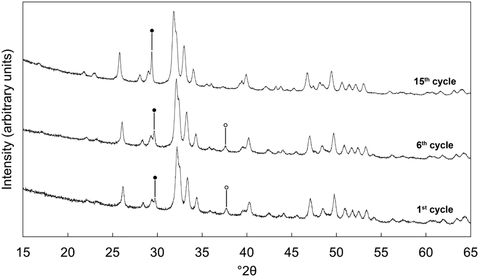 | ||
| Fig. 5 Normalised (Imax = 100) XRD patterns of the x = 2.5 apatite after being cycled multiple times (1, 6 or 15 carbonation/regeneration steps at 500 °C), with the final decarbonation for each performed at 600 °C. Intense reflections corresponding to secondary phases of calcite and calcium oxide are marked using ● and ○ respectively. | ||
Fig. 6 shows FTIR absorbance spectra of the x = 2.5 material across the first and last (15th) cycles. ν2 (890–845 cm−1) and ν3 (1600–1300 cm−1) carbonate bands were seen in each of these spectra, with these increasing in intensity (data are normalised) after the apatite had been heated in CO2 and subsequently diminishing when the material was heated in air. Moreover, whilst the ν2 band remained quite broad in each case, distinct contributions corresponding to A and B-type carbonate substitution respectively,45 could be seen in each carbonated sample at approximately 1480 and 1415 cm−1. This behaviour was representative of each of the cycles and therefore it appeared that the material functioned by way of the simultaneous substitution of carbonate ions onto both hydroxyl and phosphate sites during carbonation and their subsequent loss during regeneration. It is known that the distribution of carbonate ions over A and B sites in carbonate-substituted apatites can be approximated by comparing the intensities or peak areas of the carbonate peaks present in the ν2 region.46,47 Therefore, this carbonate region was deconvoluted to try to better understand the substitution of carbonate ions during cycling. In our previous work,22 we deconvoluted this region into four distinct peaks, two each for A-type and B-type carbonate, although a reasonable fit could be achieved using 3 peaks. Here, we found that more reasonable fits could be achieved by fitting only one peak assigned to B-type carbonate substitution between 870–869 cm−1 alongside two peaks assigned to A-type carbonate at 879–877 cm−1 (labelled A1) and 861–858 cm−1 (A2) respectively. An example of the peak deconvolution over the first cycle is shown in Fig. 7, with the peak positions and areas for the first and last cycles presented in Table 3. The B/A ratio (i.e. the ratio B/(A1 + A2)) is also shown in Table 3. The increasing B/A ratio upon carbonation suggested that significantly more carbonate substituted onto and were subsequently lost from B-sites relative to A-sites. This would support the hypothesis that the increased CO2 carrying capacity with K+/CO32− co-substitution was due to additional sites (i.e. phosphate sites) having been made available for exchange with carbon dioxide. However, this could not be confirmed as the heating temperatures were not high enough to produce samples sufficiently crystalline to allow for full Rietveld refinement (i.e. site occupancies, thermal parameters etc.) of diffraction data to be carried out.
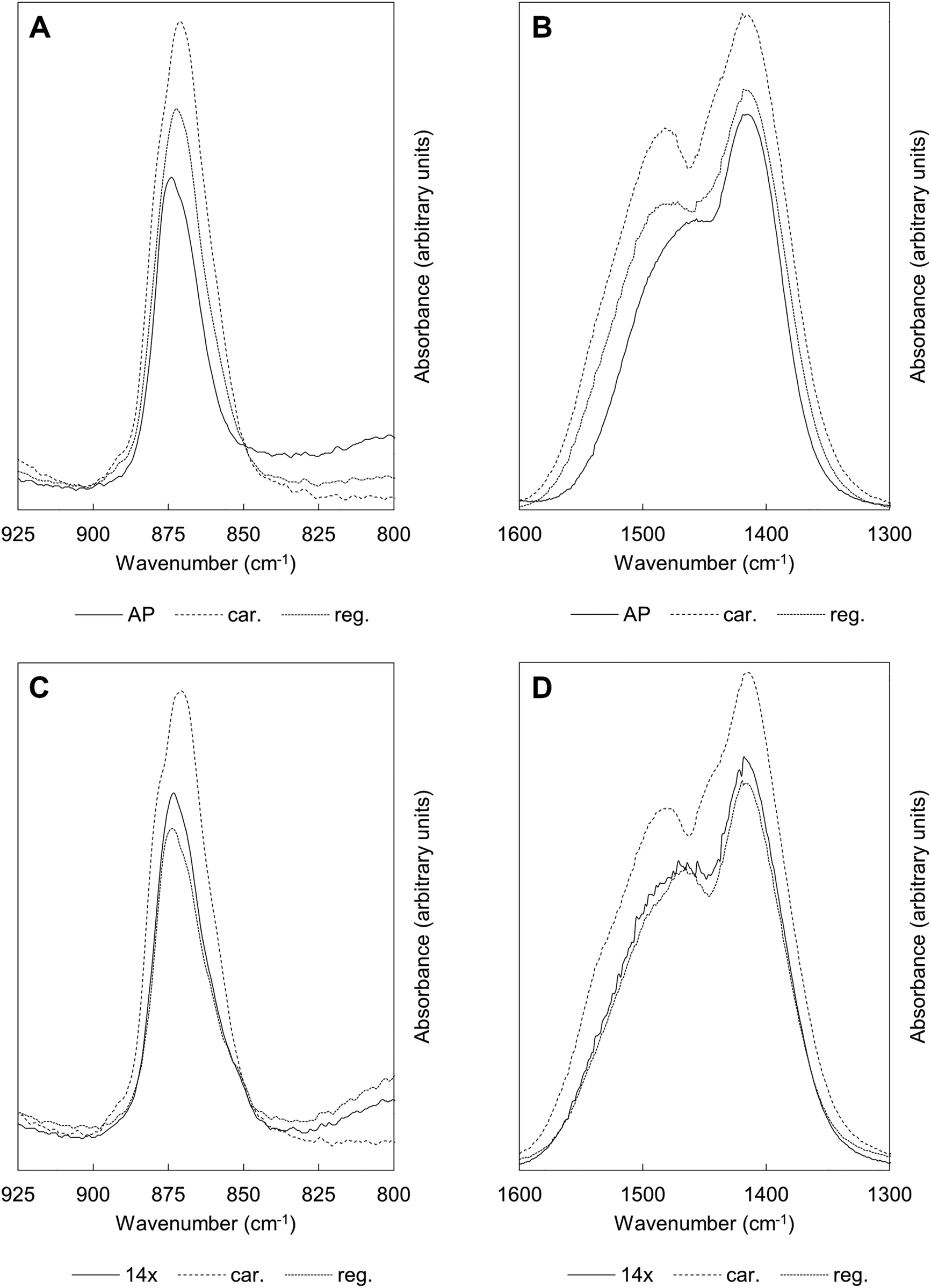 | ||
| Fig. 6 Normalised (Amax = 100) FTIR absorbance spectra showing the ν2 (925–800 cm−1) and ν3 (1600–1300 cm−1) carbonate bands of the apatite over the course of the (A), (B) 1st and (C), (D) 15th cycles. ‘14×’ corresponds to the material that had been subjected to 14 cycles, used as a benchmark to study the behaviour of these bands over the last carbonation/regeneration cycle. Carbonated samples are represented by ‘car.’ whilst ‘reg.’ denotes regenerated samples heated in air. | ||
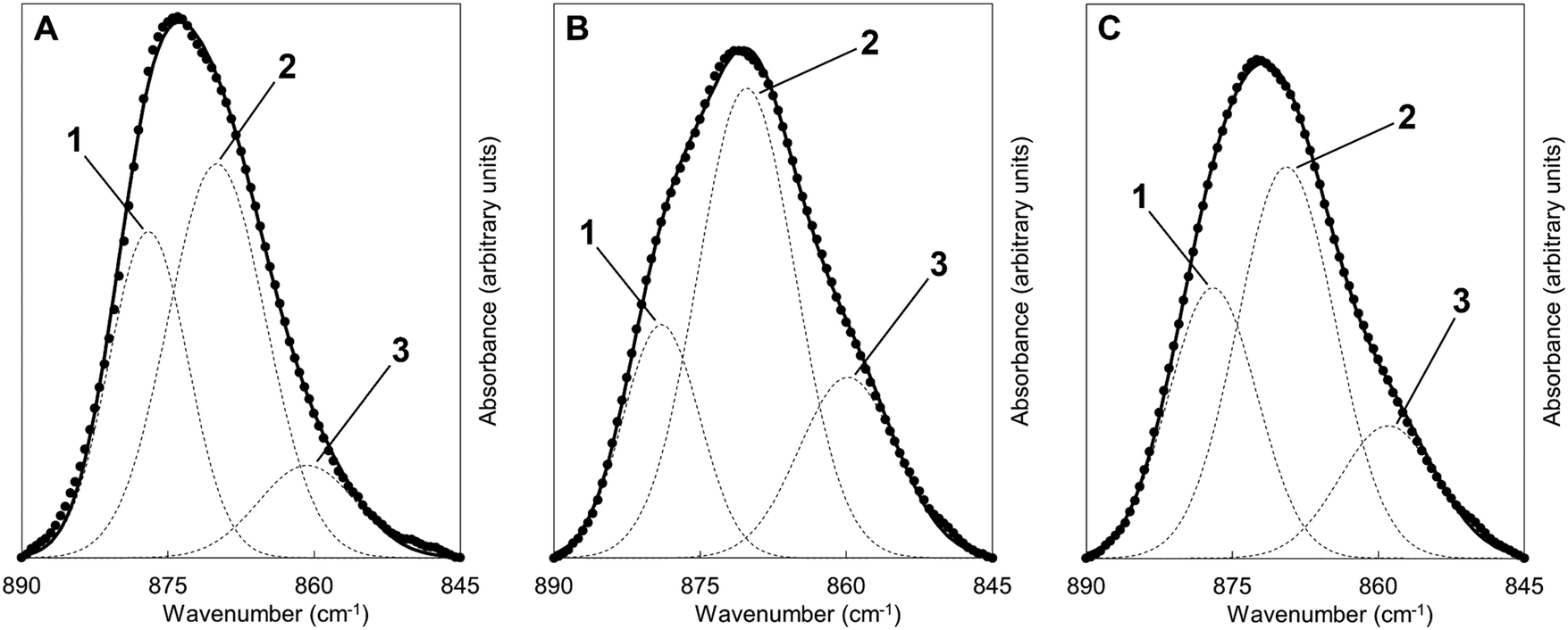 | ||
| Fig. 7 Deconvolution of the carbonate ν2 region of the FTIR spectra of the x = 2.5 apatite (A) at the start of the first cycle i.e. the AP sample, (B) after carbonation and (C) after sorbent regeneration. Dashed lines correspond to the individual fitted peaks and the solid line the corresponding model spectra; the raw data is presented as isolated data points. The y-axis was plotted using an arbitrary scale. | ||
| Peak position (cm−1) and area (%) | ||||||
|---|---|---|---|---|---|---|
| 1st cycle | 15th cycle | |||||
| AP | 1st car | 1st reg. | 14× | 15th car. | 15th reg. | |
| Peak 1 – A1 | 877 (35%) | 879 (22%) | 877 (32%) | 877 (32%) | 879 (23%) | 877 (32%) |
| Peak 2 – B | 870 (53%) | 870 (56%) | 869 (51%) | 869 (50%) | 870 (55%) | 869 (50%) |
| Peak 3 – A2 | 861 (12%) | 860 (22%) | 859 (17%) | 858 (18%) | 859 (21%) | 858 (18%) |
| B/A ratio | 1.11 | 1.29 | 1.04 | 1.00 | 1.25 | 1.00 |
The calculated lattice parameters of the apatite as-prepared and at each carbonation and regeneration interval are presented as a function of the number of carbonation–regeneration cycles in Fig. 8. Although the c unit cell parameter did not exhibit a significant change during cycling, the a lattice parameter expanded upon carbonation and decreased when the material was heated in air. A-type carbonate substitution is known to bring about an expansion in the a-axis and a contraction in the c-axis, whilst B-type carbonate substitution has the opposite effects on the lattice parameters of hydroxyapatite.45 Therefore, these trends can be used as evidence that the substitution of carbonate ions on hydroxyl sites during carbonation and the loss of these ions during regeneration had more of an impact on the crystal structure, and thus the unit cell parameters, of the material than did the substitution and subsequent loss of carbonate ions onto/from phosphate sites. The unit cell volume also expanded with cycling, which one would expect when carbonate ions substitute for the relatively smaller hydroxyl ions according to Vegard's law.48
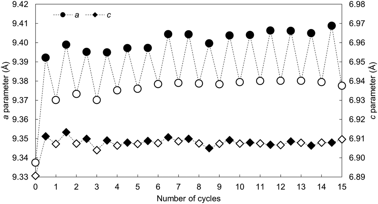 | ||
| Fig. 8 The a and c lattice parameters of the x = 2.5 apatite as-prepared and over 15 carbonation–regeneration cycles. Filled markers represent carbonated samples whereas the open markers represent the as-prepared sample and samples regenerated in air. | ||
4. Conclusions
In this study, stoichiometric hydroxyapatite and several potassium–carbonate co-substituted apatites were subjected to carbonation–regeneration cycles in order to explore their applicability for carbon capture at 500 °C. Whilst all the materials were functional at this temperature (with the carbonate contents rising and falling upon carbonation and regeneration respectively), the CO2 carrying capacity rose alongside the degree of K+/CO32− co-substitution. In fact, the x = 2.5 composition exhibited a carrying capacity more than seven times larger than stoichiometric HA—the first demonstration of the ability to improve the carrying capacity of these sorbents via ionic substitution mechanisms. This improved performance was attributed to the co-substitution having generated additional structural sites for interchange with CO2. In an extended study, the CO2 carrying capacity of one of the compositions was observed to increase slightly on subsequent carbonation/regeneration cycles following an initial drop. This is another significant result when one compares the behaviour of the material to calcium oxide, a widely studied solid sorbent which suffers from a catastrophic loss of reactivity with respect to CO2 after only a few cycles. FTIR spectroscopy suggested that the apatite material functioned by way of the simultaneous substitution of carbonate ions onto hydroxyl and phosphate sites during carbonation followed by the subsequent loss of these ions when the material was heated in air. Whilst this study represents a positive step in the development of apatite materials for carbon capture further work is required, particularly focussed on the testing of these materials in a more ‘real-world’ scenario. For example, the materials must be tested in an environment where the partial pressure of CO2 is low (e.g. a flue gas mixture). Additionally, the potential effect of water vapour should be investigated as this may negatively impact the structural integrity of the materials whilst also reducing the efficiency of capture due to competition between CO2 and H2O for adsorption sites.Author contributions
Duncan A. Nowicki: conceptualization; methodology; investigation; data curation; formal analysis; writing – original draft; writing – review & editing. Iain R. Gibson: conceptualization; formal analysis; funding acquisition; writing – review & editing. Janet M. S. Skakle: conceptualization; writing – review & editing.Conflicts of interest
The authors have no conflicts to declare related to this study.Acknowledgements
The authors would like to acknowledge the University of Aberdeen and the Royal Commission for the Exhibition of 1851 for providing financial support as well as Mr Colin Taylor of the University of Aberdeen for his assistance in collecting some of the experimental data presented here.References
- IPCC. Climate Change 2014: Synthesis Report. Contribution of Working Groups I, II and III to the Fifth Assessment Report of the Intergovernmental Panel on Climate Change. IPCC, Geneva, Switzerland; 2014.
- IPCC. IPCC Special Report on Carbon Dioxide Capture and Storage. Prepared by Working Group III of the Intergovernmental Panel on Climate Change. Cambridge, United Kingdom and New York, NY, USA: Cambridge University Press; 2005.
- Renewable Energy Policy Network for the 21st Century. Renewables 2018 Global Status Report. 2018.
- G. T. Rochelle, Amine Scrubbing for CO2 Capture, Science, 2009, 325, 1652–1654, DOI:10.1126/science.1176731.
- M. A. Scibioh and B. Viswanathan, Chapter 3 – CO2—Capture and Storage, Carbon Dioxide to Chemicals and Fuels, 2018, pp.61–130. DOI:10.1016/B978-0-444-63996-7.00003-1.
- J. Pires, F. Martins, M. Alvim-Ferraz and M. Simões, Recent Developments on Carbon Capture and Storage: An Overview, Chem. Eng. Res. Des., 2011, 89, 1446–1460 CrossRef CAS.
- J. Wang, L. Huang, R. Yang, Z. Zhang, J. Wu and Y. Gao, et al., Recent Advances in Solid Sorbents for CO2 Capture and New Development Trends, Energy Environ. Sci., 2014, 7, 3478–3518 RSC.
- K. Nakagawa and T. Ohashi, A Novel Method of CO2 Capture From High Temperature Gases, J. Electrochem. Soc., 1998, 145, 1344–1346 CrossRef CAS.
- K. G. Lakshminarayana Bhatta, S. Seetharamu and S. Olivera, Lithium Ceramics for High Temperature CO2 Capture: A Review, J. CPRI, 2014, 10, 395–408 Search PubMed.
- M. Kato, S. Yoshikawa and K. Nakagawa, Carbon Dioxide Absorption by Lithium Orthosilicate in a Wide Range of Temperature and Carbon Dioxide Concentrations, J. Mater. Sci. Lett., 2002, 21, 485–487 CrossRef CAS.
- M. Erans, V. Manovic and E. J. Anthony, Calcium Looping Sorbents for CO2 Capture, Appl. Energy, 2016, 180, 722–742, DOI:10.1016/j.apenergy.2016.07.074.
- S. Choi, J. H. Drese and C. W. Jones, Adsorbent Materials for Carbon Dioxide Capture From Large Anthropogenic Point Sources, ChemSusChem, 2009, 2, 796–854 CrossRef CAS PubMed.
- G. S. Grasa and J. C. Abanades, CO2 Capture Capacity of CaO in Long Series of Carbonation/Calcination Cycles, Ind. Eng. Chem. Res., 2006, 45, 8846–8851 CrossRef CAS.
- C. C. Dean, J. Blamey, N. H. Florin, M. J. Al-Jeboori and P. S. Fennell, The Calcium Looping Cycle for CO2 Capture from Power Generation, Cement Manufacture and Hydrogen Production, Chem. Eng. Res. Des., 2011, 89, 836–855 CrossRef CAS.
- R. H. Borgwardt, Sintering of Nascent Calcium Oxide, Chem. Eng. Sci., 1989, 44, 53–60, DOI:10.1016/0009-2509(89)85232-7.
- A. Coppola, P. Salatino, F. Montagnaro and F. Scala, Hydration-Induced Reactivation of Spent Sorbents for Fluidized Bed Calcium Looping (Double Looping), Fuel Process. Technol., 2014, 120, 71–78 CrossRef CAS.
- D. Beruto, G. Spinolo, L. Barco, U. A. Tamburini and G. Belleri, On the Nature of the Crystallographic Disorder in Submicrometer Particles of Ca(OH)2 Produced by Vapour Phase Hydration, Ceram. Int., 1983, 9, 22–25 CrossRef CAS.
- F.-C. Yu, N. Phalak, Z. Sun and L.-S. Fan, Activation Strategies for Calcium-Based Sorbents for CO2 Capture: A Perspective, Ind. Eng. Chem. Res., 2011, 51, 2133–2142 CrossRef.
- P. Sun, C. J. Lim and J. R. Grace, Cyclic CO2 Capture by Limestone-Derived Sorbent During Prolonged Calcination/Carbonation Cycling, AIChE J., 2008, 54, 1668–1677 CrossRef CAS.
- E. Landi, S. Riccobelli, N. Sangiorgi, A. Sanson, F. Doghieri and F. Miccio, Porous Apatites as Novel High Temperature Sorbents for Carbon Dioxide, Chem. Eng. J., 2014, 254, 586–596, DOI:10.1016/j.cej.2014.05.070.
- O. H. Ojeda-Niño, C. Blanco and C. E. Daza, High Temperature CO2 Capture of Hydroxyapatite Extracted From Tilapia Scales, Univ. Sci., 2017, 22, 215–236 CrossRef.
- D. A. Nowicki, J. M. S. Skakle and I. R. Gibson, Potassium–Carbonate Co-substituted Hydroxyapatite Compositions: Maximising the Level of Carbonate Uptake for Potential CO2 Utilisation Options, Mater. Adv., 2022, 3, 1713–1728 RSC.
- R. Liu and L. Rattan, Synthetic Apatite Nanoparticles as a Phosphorus Fertilizer for Soybean (Glycine Max), Sci. Rep., 2014, 4, 5686 CrossRef CAS.
- D. Montalvo, M. J. McLaughlin and F. Degryse, Efficacy of Hydroxyapatite Nanoparticles as Phosphorus Fertilizer in Andisols and Oxisols, Soil Sci. Soc. Am. J., 2015, 79, 551–558 CrossRef CAS.
- S.-L. Bee and Z. A. A. Hamid, Hydroxyapatite Derived From Food Industry Bio-wastes: Syntheses, Properties and its Potential Multifunctional Applications, Ceram. Int., 2020, 46, 17149–17175 CrossRef CAS.
- P. Kamalanathan, S. Ramesh, L. T. Bang, A. Niakan, C. Y. Tan and J. Purbolaksono, et al., Synthesis and Sintering of Hydroxyapatite Derived From Eggshells as a Calcium Precursor, Ceram. Int., 2014, 40, 16349–16359, DOI:10.1016/j.ceramint.2014.07.074.
- M. Akao, H. Aoki and K. Kato, Mechanical Properties of Sintered Hydroxyapatite for Prosthetic Applications, J. Mater. Sci., 1981, 16, 809–812 CrossRef CAS.
- A. Jillavenkatesa and R. A. Condrate Sr., Sol–gel processing of hydroxyapatite, J. Mater. Sci., 1998, 33, 4111–4119 CrossRef CAS.
- A. Afshar, M. Ghorbani, N. Ehsani, M. R. Saeri and C. C. Sorrell, Some Important Factors in the Wet Precipitation Process of Hydroxyapatite, Mater. Des., 2003, 24, 197–202, DOI:10.1016/S0261-3069(03)00003-7.
- D. Alvarez and J. Carlos Abanades, Determination of the Critical Product Layer Thickness in the Reaction of CaO with CO2, Ind. Eng. Chem. Res., 2005, 44, 5608–5615, DOI:10.1021/ie050305s.
- J. Blamey, E. J. Anthony, J. Wang and P. S. Fennell, The Calcium Looping Cycle for Large-Scale CO2 Capture, Prog. Energy Combust. Sci., 2010, 36, 260–279, DOI:10.1016/j.pecs.2009.10.001.
- T. Degen, M. Sadki, E. Bron, U. König and G. Nénert, The HighScore Suite, Powder Diffr., 2014, 29, S13–S18 CrossRef CAS.
- K. Sudarsanan and R. A. Young, Significant Precision in Crystal Structure Details: Holly Springs Hydroxyapatite, Acta Crystallogr., 1969, B25, 1534–1543 CrossRef.
- J. S. O. Evans and I. R. Evans, Structure Analysis from Powder Diffraction Data: Rietveld Refinement in Excel, J. Chem. Educ., 2021, 98, 495–505 CrossRef CAS.
- ICDD. PDF Card No. 9-432. Newton Square, Pennsylvania, USA n.d.
- Gibson IR. Personal Communication with Duncan Alexander Nowicki, 14th December 2018.
- D. A. Nowicki, J. M. Skakle and I. R. Gibson, Faster Synthesis of A-type Carbonated Hydroxyapatite Powders Prepared by High-Temperature Reaction, Adv. Powder Technol., 2020, 31, 3318–3327 CrossRef CAS.
- T. Tonegawa, T. Ikoma, T. Yoshioka, N. Hanagata and J. Tanaka, Crystal Structure Refinement of A-type Carbonate Apatite by X-ray Powder Diffraction, J. Mater. Sci., 2010, 45, 2419–2426 CrossRef CAS.
- T. Tonegawa, T. Ikoma, Y. Suetsugu, N. Igawa, Y. Matsushita and T. Yoshioka, et al., Thermal Expansion of Type A Carbonate Apatite, Mater. Sci. Eng., B, 2010, 173, 171–175 CrossRef CAS.
- Y. X. Pang and X. Bao, Influence of Temperature, Ripening Time and Calcination on the Morphology and Crystallinity of Hydroxyapatite Nanoparticles, J. Eur. Ceram. Soc., 2003, 23, 1697–1704, DOI:10.1016/S0955-2219(02)00413-2.
- J. Valverde, P. Sanchez-Jimenez and L. Perez-Maqueda, Calcium-Looping for Post-combustion CO2 Capture. On the Adverse Effect of Sorbent Regeneration Under CO2, Appl. Energy, 2014, 126, 161–171 CrossRef CAS.
- J. Bai, J. Huang, Q. Jiang, W. Jiang, M. Demir and M. Kilic, et al., Synthesis and Characterization of Polyphenylene Sulfide Resin-derived S-Doped Porous Carbons for Efficient CO2 Capture, Colloids Surf., A, 2023, 131916 CrossRef CAS.
- J. Bai, J. Huang, Q. Yu, M. Demir, E. Akgul and B. N. Altay, et al., Fabrication of Coconut Shell-Derived Porous Carbons for CO2 Adsorption Application, Front. Chem. Sci. Eng., 2023, 1–9 CAS.
- T. Lu, J. Bai, J. Huang, Q. Yu, M. Demir and M. Kilic, et al., Self-Activating Approach for Synthesis of 2,6-Naphthalene Disulfonate Acid Disodium Salt-Derived Porous Carbon and CO2 Capture Performance, Energy Fuels, 2023, 37, 3886–3893 CrossRef CAS.
- R. Z. LeGeros, O. R. Trautz, E. Klein and J. P. Legeros, Two Types of Carbonate Substitution in the Apatite Structure, Experientia, 1969, 25, 5–7 CrossRef CAS PubMed.
- M. E. Fleet, Infrared Spectra of Carbonate Apatites: ν2-Region Bands, Biomaterials, 2009, 30, 1473–1481, DOI:10.1016/j.biomaterials.2008.12.007.
- C. Rey, V. Renugopalakrishnan, M. Shimizu, B. Collins and M. J. Glimcher, A Resolution-Enhanced Fourier Transform Infrared Spectroscopic Study of the Environment of the CO32− Ion in the Mineral Phase of Enamel During its Formation and Maturation, Calcif. Tissue Int., 1991, 49, 259–268, DOI:10.1007/BF02556215.
- A. R. West, Solid State Chemistry and its Applications: Student Edition, John Wiley & Sons, 2nd edn, 2014 Search PubMed.
Footnote |
| † Electronic supplementary information (ESI) available. See DOI: https://doi.org/10.1039/d3ma00909b |
| This journal is © The Royal Society of Chemistry 2024 |