
Theoretical and experimental investigation of Al3+ ion-suppressed phase-separation structures in rare-earth-doped high-phosphorus silica glasses†
He-He
Dong
ab,
Jin-Jun
Ren
a,
Ying-Gang
Chen
ab,
Fan
Wang
a,
Dan-Ping
Chen
 a,
Lu
Deng
a,
Chong-Yun
Shao
a,
Shi-Kai
Wang
*a,
Chun-Lei
Yu
*ac and
Li-Li
Hu
*ac
a,
Lu
Deng
a,
Chong-Yun
Shao
a,
Shi-Kai
Wang
*a,
Chun-Lei
Yu
*ac and
Li-Li
Hu
*ac
aKey Laboratory of Materials for High Power Laser, Shanghai Institute of Optics and Fine Mechanics, Chinese Academy of Sciences, Shanghai 201800, People's Republic of China. E-mail: woshiwsk@163.com; sdycllcy@163.com; hulili@siom.ac.cn
bCentre of Materials Science and Optoelectronics Engineering, University of Chinese Academy of Sciences, Beijing 100049, People's Republic of China
cHangzhou Institute for Advanced Study, University of Chinese Academy of Sciences, Hangzhou 310024, People's Republic of China
First published on 20th December 2023
Abstract
Rare-earth-doped silica-based composite glasses (Re-SCGs) are widely used as high-quality laser gain media in defense, aerospace, energy, power, and medical applications. The variable regional chemical environments of Re-SCGs can induce new photoluminescence properties of rare-earth ions but can cause the selective aggregation of rare-earth ions, limiting the application of Re-SCGs in the field of high-power lasers. Here, topological engineering is proposed to adjust the degree of cross-linking of phase-separation network chains in Re-SCGs. A combination of experimental and theoretical characterization techniques suggested that the selective aggregation of rare-earth ions originates from the formation of phase-separated structures in glasses. The decomposition of nanoscale phase separation structures to the sub-nanometer scale, enabled by incorporating Al3+ ions, not only maintains the high luminescence efficiency of rare earth ions but also increases light transmittance and reduces light scattering. Furthermore, our investigation encompassed the exploration of the inhibitory mechanism of Al3+ ions on phase-separation structures, as well as their influence on the spectral characteristics of Re-SCGs. This work provides a new design concept for composite glass materials doped with rare-earth ions and could broaden their application in the field of high-power lasers.
1. Introduction
As the core gain medium of fiber lasers, rare-earth (RE)-doped silica-based glasses play an important role in improving the conversion efficiency and output power.1–6 Currently, to reduce the influence of the fluorescence quenching effect, mainstream RE-doped silica-based glasses usually introduce low levels of co-dopants (e.g. Al, Al–P, F, etc.) to increase the solubility of RE ions, which improves the gain efficiency.7–10 However, with the rapid development of high-power fiber lasers, it has become difficult for low-concentration co-doped silica-based glasses to meet the requirements of high-power operation.11–14In recent years, RE-doped silica-based composite glasses (Re-SCGs) have attracted considerable attention due to their high gain efficiencies, tunable crystal-field environments, and unique thermodynamic properties.15–17 As is known, the luminescence efficiency of RE ions is closely related to their chemical state and the surrounding chemical environment provided by the host glass.18 Appropriate doping, heat treatment, or deliberate topology design can be employed to make RE ions occupy sites with very different chemical environments, which have been shown to induce new photoluminescence features such as ultra-broadband and enhanced up/down conversion emission.6,19–21 However, achieving a stable and homogeneous distribution of RE ions at sites where the chemical environment changes significantly remains a major challenge, especially in composite glasses assembled using two or more different glass network formers. Previous studies have shown that in composite glass networks assembled using two or more network formers, one of the glass network formers does still dominate.17,22 For example, in boron-phosphorus composite glasses and boron–silicon composite glasses, although certain moderate-scale B–O–P and B–O–Si associations exist, they are still dominated by [BO3] trihedral and [SiO4] tetrahedral structures, respectively.22–25 In such composite glasses, most of the RE ions are confined to a specific glass network. This local enrichment of RE ions may cause severe non-linear effects and even concentration quenching effects.
Highly phosphorus doped silica-based composite glasses are a key research area for high power gain fibers owing to their high solubility for RE ions and excellent anti-photon darkening capability.26–30 In recent years, an increasing number of studies have been devoted to modulating the degree of constraint of the phosphate network on RE ions in order to achieve a balance between high luminescence efficiency and high doping homogeneity.30–33 Likhachev et al. prepared high-quality phosphorus–silica composite glass fibers by using the multilayer modified chemical vapor deposition (MCVD) technique.26,27 This multilayer deposition and interdiffusion method improved the doping homogeneity of RE ions to some extent. However, owing to the limitations of the MCVD preparation technique, some missing element depressions in the core regions of the fibers remained. Zhang et al. used a new method called “melt-in-melt” to prepare bulk phosphorus–silica composite glass; this method facilitated effective mixing of arbitrary phosphorus and silicon ratios but was still severely plagued by uneven doping of the elements and the lack of high transmittance of the glass.21
Here, we traced the origin of selective aggregation of RE ions in highly phosphorus-doped silica-based composite glasses and confirmed that it results from the formation of phase-separated structures. We report a new strategy based on topological engineering: using in situ embedding of aluminum ions, the interaction between Al and P ions during vitrification induces Al atoms to cut the P–O–P linkages and generate Al–O–P linkages, thus inducing the breakage and rearrangement of the phase-separated structure. To verify the superiority of this strategy in suppressing the phase separation structures, erbium (Er) and ytterbium (Yb) ions were introduced as indicators in silica-based high-phosphorus composite glasses (hereafter referred to as Er–Yb co-doped high-phosphorus silica-based glasses). Advanced techniques such as classical molecular dynamics simulations, high-resolution transmission electron microscopy (HRTEM), solid-state nuclear magnetic resonance (NMR), and advanced pulse electron paramagnetic resonance (EPR) combined with spectroscopic information were used to characterize the mechanism of phase separation structure evolution and suppression in Er–Yb co-doped high-phosphorus silica-based glasses. This strategy proved successful in inducing the decomposition of nanoscale phase-separated structures to sub-nanoscale, which both perpetuates the high luminescence efficiency of RE ions and increases transmittance and reduces light scattering.
2. Results and discussion
2.1. Material design and preparation
Phosphate and silicate glass networks, as separate glass network formers, are poorly soluble in each other.34 In addition, high-P silica-based glasses are highly viscous at high temperatures, rendering conventional mechanical stirring almost impossible. In addition, elemental phosphorus exhibits typical irregular volatilization properties at high temperatures. Therefore, obtaining high-phosphorus silica-based glasses with stable compositions and homogeneous structures is a major challenge in this field.35In Er–Yb co-doped high-phosphorus silica-based glasses, the enrichment of phosphorus elements is usually accompanied by the aggregation of RE ions, which is also considered to be a precursor to glass crystallization, which is undoubtedly detrimental for high-power fiber laser materials.30,33 To solve this problem, we started using active precursor powders to promote the homogeneous mixing of each doping element at the molecular level, ensuring that the local enrichment of phosphorus elements can occur homogeneously throughout the glass network during vitrification. At this point, the Al3+ ions latent in the precursor powder can continuously trim the degree of cross-linking of the phosphate glass network during the vitrification process to achieve homogeneous trimming of the large phosphorus-rich areas into numerous small phosphorus-rich areas, thereby achieving a homogeneous distribution of the phosphate network throughout the glass network. Fig. S1 (ESI†) illustrates the X-ray diffraction (XRD) results of the dried gel particles obtained from the heat-treated EYP10 and EYPA10 samples, demonstrating their amorphous nature without any indication of crystallization.
The EYP10 (0.04Er2O3–0.44Yb2O3–10P2O5–89.52SiO2, mol%) and EYPA10 (0.04Er2O3–0.44Yb2O3–10P2O5–1Al2O3–88.52SiO2, mol%) glasses were prepared using a sol–gel method combined with high-temperature sintering of the nanopowders (see Fig. 1).35,36 The tested compositions of the two glasses are shown in Fig. 2a, where the loss of phosphorus was fixed at approximately 10%. These data were obtained via inductively coupled plasma atomic emission spectrometry (ICPAES, Thermo iCAP 6300). Fig. 2b shows the X-ray diffraction (XRD) data for both glasses, which indicate that both glasses have an amorphous structure with no obvious appearance of crystallization. Fig. 2c shows the photographs of both glasses, and Fig. 2d shows their transmittance curves in the ultraviolet-visible spectroscopic range (200–800 nm), where the thickness of the test glasses is limited to 2 mm. The transmittance of the EYP10 glass is significantly lower than that of the EYPA10 glass. Initially, we assumed that inhomogeneous doping of the elements was the main cause of this discrepancy. However, the results of the cross-sectional electron probe microanalysis (EPMA) mapping of the EYP10 glass hardly support this view (see Fig. S2, ESI†). Therefore, we speculate that the evolution of the microtopology within the glass may be the main cause of this phenomenon.
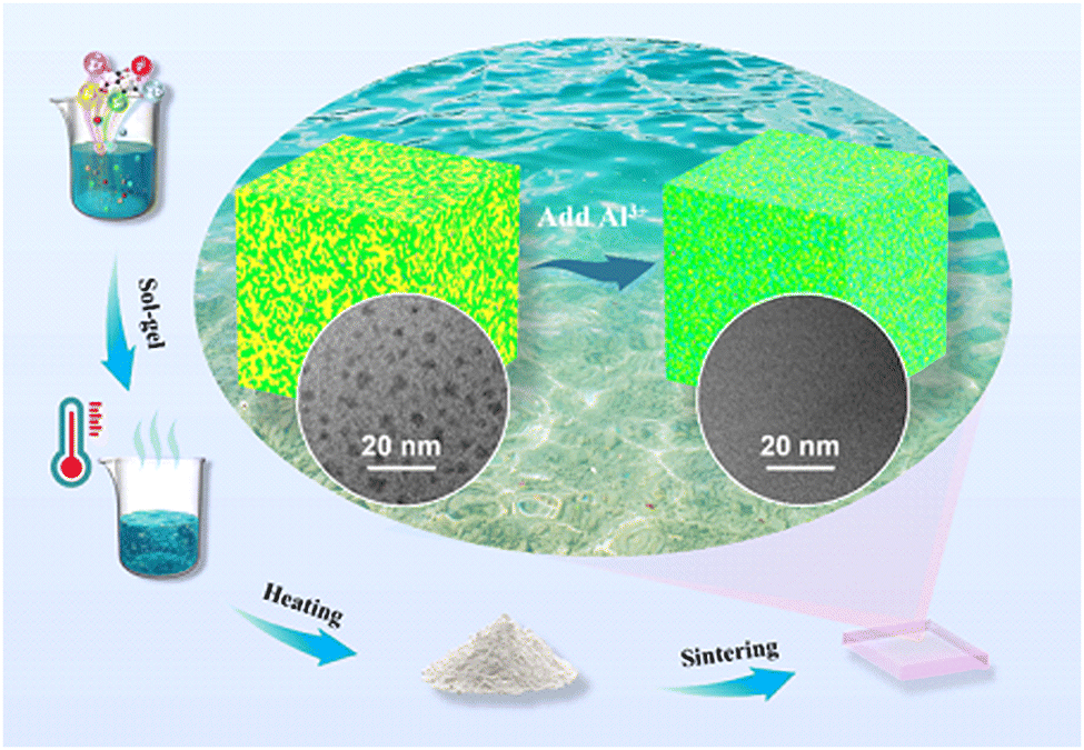 | ||
| Fig. 1 Schematic diagram of the glass preparation process; the inset shows the suppression process of the glass phase separation structure. | ||
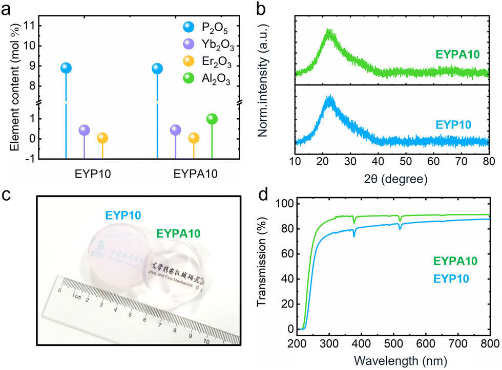 | ||
| Fig. 2 (a) Measured compositions, (b) XRD data, (c) real photographs of EYP10 and EYPA10 glasses, and (d) transmittance curves in the ultraviolet-visible spectral range (200–800 nm) for EYP10 and EYPA10 glasses. | ||
2.2. Emergence and suppression of phase separation
Fig. 3a–d show the transmission electron microscopy (TEM) and HRTEM images of the EYP10 glass. A typical phase separation phenomenon (black teardrop-like structure), which is diffusely distributed throughout the glass matrix, is clearly observed in Fig. 3b. The particle size of the droplet-shaped second-phase particles is approximately 6–14 nm, which is based on the statistical distribution of the particle sizes of all second-phase particles presented in Fig. 3b. In addition, irregular crystal lattice stripes are observed in the HRTEM images of the EYP10 glass in Fig. 3d. Similar irregular lattice streaks were observed in other second-phase particles of the EYP10 glass, which we consider to be the transitional stage of crystallization, i.e., the pre-crystalline phase. The transmittance curve of the EYP10 glass has a larger background slope than that of the EYPA10 glass in the range of 300–800 nm (see Fig. 2d), which is mainly due to the obvious phase separation and pre-crystallization phenomenon in the EYP10 glass, which triggers the light scattering phenomenon and causes its background intensity to gradually increase as the wavelength decreases.37 Although the electron diffraction data of this area showed that its local structure was amorphous, the appearance of irregular crystal lattice stripes was sufficient to prove that nanocrystals appeared in the local area of the EYP10 glass. The appearance of such nanocrystals is guided by a strong phase separation phenomenon.17,22 To further determine the chemical composition of the second-phase particles in the EYP10 glass, the area containing the second-phase particles shown in Fig. 3e was selected for an energy-dispersive spectrometer (EDS) line scan. The results of the line scan are shown in Fig. 3f. The main chemical components of the second-phase particles are phosphorus and ytterbium. It should be noted that continuous irradiation of thin glass with a high-energy electron beam leads to a gradual increase in the size of the second-phase particles, although this does not affect our determination of the chemical composition of the second-phase particles. However, the characteristic signals of erbium ions were not effectively monitored. We attribute this phenomenon to the following reasons: 1 the doping content of the erbium ions was too low to reach the detection limit of the instrument: 2 the weak characteristic signals of the low-content erbium ions were reabsorbed in the detector window, resulting in the ineffective monitoring of their characteristic signals. However, this does not affect our judgment about the chemical composition of the second-phase particles because erbium and ytterbium ions have approximately the same atomic structure and very similar ionic radii, and we have enough reasons to believe that the second-phase particles are actually aggregates of RE ions (erbium and ytterbium ions) and phosphorus elements. Furthermore, an EDS line scan was used to monitor the characteristic signal of elemental Si in the second-phase particles. Interestingly, its characteristic signal did not show an obvious depression or bulge in the second-phase particle region but showed a gentle fluctuation throughout the scan region. There are two main explanations for this phenomenon: 1 the presence of a large number of silicon elements around the second-phase particles, resulting in signal interference or signal superposition of silicon elements; 2 the surface of the second-phase particles remained as a thin layer of silica after the glass sample was sheared thin by argon ions. | ||
| Fig. 3 TEM bright-field images of the EYP10 glass at different scales: (a) 500 nm, (b) 50 nm, where the inset shows the particle size distribution statistics of the second phase particles, and (c) 20 nm. (d) HRTEM image of the EYPA10 glass; the inset shows the SAED image. (e) and (f) TEM dark-field image representing the position of the EDS line scan and a spectrum of representative second phase particles. TEM bright-field images of the EYPA10 glass at different scales: (g) 500 nm, (h) 50 nm, and (i) 20 nm. (j) HRTEM image of the EYPA10 glass; the inset shows the SAED image. (k) TEM bright-field image and EDS analysis of the EYPA10 glass. All glasses were pretreated by ion thinning before TEM testing. | ||
Fig. 3g–j show the TEM and HRTEM images of the EYPA10 glass. To facilitate a valid comparison between the TEM and HRTEM images of the EYP10 glass, the two glasses were kept strictly consistent in terms of the sample preparation process, test environment, and test parameter settings. Surprisingly, we could hardly find any significant local lining difference in the TEM images of the EYPA10 glass (Fig. 3h and i), which indicates that there was almost no phase separation in the EYPA10 glass. In addition, no obvious crystal lattice streaks are observed in the HRTEM images of the EYPA10 glass, and the selected area electron diffraction (SAED) image in this region indicates that the local structure is amorphous. Furthermore, the energy-dispersive X-ray spectroscopy (EDS) surface scan data (Fig. 3k) confirm that the distribution of elements is more homogeneous and that phase separation is significantly suppressed in the EYPA10 glass. A comparison of the TEM and HRTEM images of EYP10 and EYPA10 glasses, combined with their EDS scan results, confirms the remarkable effect of our new strategy in suppressing phase separation and mitigating RE ion aggregation in Er–Yb co-doped high-phosphorus silica-based glasses.
2.3. Evolution of the local microstructure
To theoretically reveal the evolution of interesting topologies in the EYP10 and EYPA10 glasses, MD simulations were performed separately for these two glasses, and snapshots are shown in Fig. 4a–d. Fig. 4a shows the MD-simulated structural snapshot of the EYP10 glass, where the typical phase-separation structure of the P atoms can be clearly observed, which is diffusely distributed throughout the framework of the glass structure. This result is consistent with the TEM and HRTEM images of the EYP10 glass in Fig. 3a–d. For the EYP10 glass, the introduction of a large amount of phosphorus caused massive damage to the silicon–oxygen framework. This resulted in the intertwining of the phosphorus phase with the silicon–oxygen phase, creating an interpenetrating phase-separated glass structure. A magnified view of the phase separation region in Fig. 4a is shown in Fig. 4b. Si-rich and P-rich regions can be clearly observed, with the glass framework in the Si-rich region comprising SiO4 units and that in the P-rich region comprising PO4 units. RE ions were more inclined to be present in the network gaps of the P-rich region, and this result is consistent with the results of the EDS line scan of the EYP10 glass in Fig. 3e and f. Thus, the state of phase separation determines the main distribution regions of P ions and indirectly regulates the distribution of RE ions in the glass structural framework, a phenomenon known as the phase separation confinement effect.17 The introduction of a large amount of P5+ ions can increase the solubility of RE3+ ions and improve the dispersion of RE3+ ions in the glass matrix.35 In the phosphorus-rich region, energy transfer between RE ions can easily occur because of the short distance between RE–RE ions.30,33 In addition, the P![[double bond, length as m-dash]](https://www.rsc.org/images/entities/char_e001.gif) O double bonds, which are widely present in the P-rich region, have a high phonon energy, which is favorable for suppressing the reverse energy transfer from the excited state of Er3+ ions to Yb3+ ions, thus substantially improving the efficiency of energy transfer from Yb3+ ions to Er3+ ions.30,33 However, the short distance between Re ions increases the possibility of RE ion clustering.38 Therefore, it has always been challenging to ensure the distribution of RE ions around the P5+ ions while avoiding the aggregation of RE ions.
O double bonds, which are widely present in the P-rich region, have a high phonon energy, which is favorable for suppressing the reverse energy transfer from the excited state of Er3+ ions to Yb3+ ions, thus substantially improving the efficiency of energy transfer from Yb3+ ions to Er3+ ions.30,33 However, the short distance between Re ions increases the possibility of RE ion clustering.38 Therefore, it has always been challenging to ensure the distribution of RE ions around the P5+ ions while avoiding the aggregation of RE ions.
 | ||
| Fig. 4 Snapshots of the MD simulated structures of (a) and (b) EYP10 glass and (c) and (d) EYPA10 glass, where (c) and (d) are enlarged views of the local structures at the corresponding locations in (a) and (b), respectively. | ||
Fig. 4c presents an MD-simulated structure snapshot of the EYPA10 glass, which is significantly different from that of the EYP10 glass in Fig. 4a. The phase separation structure is substantially suppressed in the EYPA10 glass, which is consistent with our design expectation. An enlarged view of the local region in Fig. 4c is shown in Fig. 4d, which reveals that the original phosphorus-rich regions are divided by the AlO4 units, and the Al atoms trim the large phosphorus-rich regions as chemical scissors to reduce the regions and evenly disperse them in the glass structural framework. Moreover, it can also be seen from Fig. 4d that the aggregation of RE ions in the phosphorus-rich region is well suppressed by continuous trimming by Al atoms in the phosphorus-rich region. This result is consistent with those shown in Fig. 3g–k.
Fig. 5a shows the normalized Raman spectra of the EYP10 and EYPA10 glasses (with the intensity of the vibrational peak at 800 cm−1 as the benchmark). We can see that the Raman spectra of both glasses are mainly composed of vibrational peaks at 430, 480, 615, 720, 808, 1170 and 1320 cm−1.28,39 Among these, 480 cm−1 and 615 cm−1 are attributed to the Si–O–Si planar quaternary rings and planar ternary rings, respectively.28,40 The bands at 430 cm−1 and 808 cm−1 are attributed to the bending vibration and symmetric stretching vibration of the Si–O–Si bond, respectively; the band near 720 cm−1 is related to the bending vibration of OP–O; the vibrations near 1170 cm−1 are usually considered to be the ensemble of Si–O–Si, P–O–Al, Al–O–Si, Al–O–P, and P–O–Si bond vibrations; and the vibrations at 1320 cm−1 are mainly from the PO double bond.28,39,41 In Fig. 5a, the vibrational peaks of the EYP10 glass at 720 cm−1 and 1320 cm−1 are significantly higher than those of the EYPA10 glass, and these two vibrational peaks can be attributed to the terminal PO groups of the P(3) unit.28,39,42 The structure of the various P(n) units is depicted schematically in Fig. S3 (ESI†). The enhanced signal of the terminal PO groups of the P(3) unit implies the presence of more mutually independent phosphate glass network structures in the EYP10 glass, which also indicates an obvious enrichment of elemental phosphorus in the EYP10 glass.
 | ||
| Fig. 5 (a) Normalized Raman spectra of EYP10 and EYPA10 glasses. (b) Deconvolutions of the reduced Raman spectra of EYP10 and EYPA10 glasses into Gaussian curves. (c) Relative areas of the deconvoluted curves considering only the spectral region displayed in (b). (d) 31P MAS NMR spectra (blue and green) and 1D-refocused INADEQUATE spectra (purple) of EYP10 and EYPA10 glasses. (e) CT-DRENAR-POST-C7 data curves for EYP10 and EYPA10 glasses. The solid curves represent the corresponding effective two-spin simulations. (f) 27Al{31P}-compensated REDOR dephasing curve of the EYPA10 glass; the inset shows the 27Al MAS NMR spectrum of the EYPA10 glass. | ||
To explain the relationship between the higher frequency Raman vibration spectra and the glass structure, the Raman vibration spectra in the range of 900–1450 cm−1 were deconvoluted into various Gaussian components and plotted in Fig. 5b. Based on the quantum chemical model of the phosphosilicate system, the Raman vibrational peak near 1320 cm−1 can be decomposed into two sub-vibrational peaks: sub-vibrational peak e (∼1345 cm−1) and sub-vibrational peak d (∼1327 cm−1), which are attributed to the stretching of the PO bond in the double OP–O–PO center and the single P(3) center (not bound to other P units), respectively.28,39 The vibrational peak near 1170 cm−1 was decomposed into three sub-vibrational peaks, namely sub-vibrational peak c (1240 cm−1), sub-vibrational peak b (1150 cm−1) and sub-vibrational peak a (1025 cm−1). The sub-vibrational peak c near 1240 cm−1 is mainly attributed to the antisymmetric stretching vibration of the Si–O bond, the sub-vibrational peak b near 1150 cm−1 is mainly attributed to the P–O–P linkage, and the sub-vibrational peak at approximately 1025 cm−1 is mainly attributed to the P–O–Si and Si–O–Si linkages.28,39Fig. 5c shows the relative areas of the inverse convolution curves of each sub-vibrational peak; sub-vibrational peaks b and e of the EYPA10 glass are lower than those of the EYP10 glass, while sub-vibrational peak d is higher than that of the EYP10 glass. This means that the number of P–O–P connections and double OP–O–PO centers in the EYPA glass is significantly reduced compared to that in the EYP10 glass, while the number of PO bonds in single P(3) centers not bonded to other P units. This indicates that the introduction of Al effectively reduced the degree of cross-linking in the phosphate glass network, significantly suppressed the enrichment of elemental phosphorus, and enhanced the antiphase separation and anticrystallization abilities of the glass.
Fig. 5d shows the 31P magic angle spinning (MAS) NMR spectra and the 1D refocused INADEQUATE spectra of the EYP10 and EYPA10 glasses. The 1D-refocused INADEQUATE experiment enables a facile distinction between those phosphate species that engage in P−O−P linking and those devoid of any P−O−P linkages.43,44 As depicted in Fig. 5d, the 31P MAS NMR spectra of the EYP10 and EYPA10 glasses show a strong similarity to their 1D-refocused INADEQUATE spectra, indicating that among all the P atoms present in these two glasses, there is at least one P–O–P link, and the P(0) units are not present in either of these glasses.45
Fig. 5e shows the CT-DRENAR-POST-C7 decay curves for the EYP10 and EYPA10 glasses under the same conditions. This experiment can effectively detect the intensity of dipole–dipole coupling between 31P and 31P in the glass.46 The sum of the squares of the experimental dipolar coupling constant,  , can be obtained using eqn (1) to characterize the average strength of the homonuclear dipole–dipole coupling between nucleus k and observed spin j.47
 | (1) |
 for the EYPA10 glass (∼4.2) is approximately half of the value of
  for the EYP10 glass (∼8.1). According to the literature, the value of
 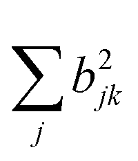 for the AlPO4 glass is approximately 3.3 × 10⁵ Hz, whereas the value of
  for both EYP10 and EYPA10 glasses is larger than 3.3 × 10⁵ Hz.40 This indicates that P–O–P linkages are present in both glasses, but the number of P–O–P linkages in the EYPA10 glass is much smaller than that in the EYP10 glass; this is consistent with the results obtained from the Raman spectrum. This result also demonstrates that the introduction of Al3+ can effectively reduce the cross-linking of the phosphate network.
The 27Al{31P} rotational-echo double resonance (REDOR) experiment was used to examine the distribution of 31P around 27Al in the EYPA10 glass using the standard REDOR pulse sequence proposed by Gullion and Schaefer, supplemented by a compensation scheme.48,49 To determine the bipolar second-moment, M2SI, a parabolic analysis of the initial part of the experimental REDOR curve (S/S0 ≤ 0.2) was performed using eqn (2):
 | (2) |
A normalized difference signal, ΔS/So = (So − S)/So, was measured in the absence (intensity So) and presence (intensity S) of the dipolar interactions between observed nuclei S and interacting nuclei I. The dependence of ΔS/So values on the systematic variation in the number of rotor cycles (N) yields the REDOR curve.50 The inset in Fig. 5f shows the 27Al MAS NMR spectrum of the EYPA10 glass. Three distinct signal peaks are observed in the 27Al MAS NMR spectrum of the EYPA10 glass at 42.0, 7.4, and −15.6 ppm, which are attributed to the four-coordinated aluminum unit (Al(IV)), five-coordinated aluminum unit (Al(V)), and six-coordinated aluminum unit (Al(VI)), respectively.45 To obtain the corresponding individual ΔS/S values of 27Al{31P}REDOR for different aluminum species, the 27Al signals of Al(IV), Al(V), and Al(VI) were integrated separately, and the detailed integration results are plotted in Fig. 5f. The average value of M2 for all three Al species is approximately 4.8 × 10⁶ rad2 s−2, which is higher than the calibrated value of M2 for AlPO4 crystals (4.6 × 10⁶ rad2 s−2), indicating that all Al atoms are exclusively bound by phosphorus–oxygen tetrahedra.40,45 Almost all the Al atoms combine with P atoms to form Al–O–P linkages, which effectively relieve the local aggregation of phosphorus elements and substantially increase the ability of the EYPA10 glass to suppress phase separation. This is consistent with the results of the EYPA10 glass in the MD-simulated structures and TEM and HRTEM images.
Fig. 6 shows the two-dimensional (2-D) hyperfine sublevel correlation (HYSCORE) spectra recorded under a magnetic field of 350 mT for the EYP10 and EYPA10 glasses. The diagonal peak located around 6.0 MHz corresponds to the Larmor frequency of the 31P (I = 1/2, abundance = 100%) nuclide.51 These correlation peaks provide direct evidence of the preference of RE ions (Er3+, Yb3+) in phosphorus-rich regions, indicating a clear confinement effect of the phase separation structure on RE ions. Furthermore, no significant difference exists between the 2D HYSCORE spectrum of the EYPA10 glass and that of the EYP10 glass, indicating that the introduction of small amounts of Al does not significantly alter the topology of the RE ions.
 | ||
| Fig. 6 2D HYSCORE spectra measured at 4K and recorded at a magnetic field strength of 350 mT for the (a) EYP10 and (b) EYPA10 glasses. | ||
Collectively, the combined experimental and theoretical results suggest that the phosphate and silicate networks form a strong glass framework in the EYPA10 glass. The introduction of Al effectively reduces the degree of cross-linking of the phosphate network, effectively suppressing the phase separation structure dominated by the phosphate network and indirectly promoting the homogeneous distribution of RE ions in the glass network. At the same time, the vast majority of RE ions are confined to the dense phosphorus phase, ensuring excellent thermodynamic stability and ultrahigh energy transfer efficiency of the EYPA10 glass.
2.4. Photophysical characterization
The absorption spectra in the NIR range (850–1650 nm) of the EYP10 and EYPA10 glasses are shown in Fig. 7a. Note that the superposition of the Er3+:4I15/2–4I11/2 transition with the Yb3+:2F7/2/2F5/2 transition results in a very strong absorption peak near 974 nm for baited Yb-doped high-phosphorus silica-based glasses. As per the Beer–Lambert equation, the absorption cross section of the Er–Yb co-doped high-phosphorus silica-based glass (Fig. 7c) is approximately five times higher than that of the conventional single erbium-doped silica glass at 974 nm, indicating that more efficient pump absorption can be obtained under excitation at 980 nm LD.52,53Fig. 7b shows the normalized fluorescence spectra of the EYP10 and EYPA10 glasses pumped by an 896-nm xenon lamp. The energy transfer efficiency between Yb3+ and Er3+ can be effectively determined based on the relative fluorescence intensities of Yb3+ and Er3+ ions. The introduction of a small amount of Al-elements does not have a substantial effect on the energy transfer between Yb3+ and Er3+. According to McCumber‘s theory, the emission cross section of the EYP10 glass at 1534 nm is only 0.02 pm2 less than (more than) that of the EYPA10 glass (Fig. 7d).53 This is primarily because the introduction of a small amount of Al does not significantly change the local environment in which RE ions are located, and the vast majority of RE ions remain in the phosphorus-rich environment. The 2D HYSCORE spectra of the EYP10 and EYPA10 glasses displayed in Fig. 6a and b support our hypothesis. | ||
| Fig. 7 (a) Absorption spectra (850–1650 nm), (b) normalized fluorescence spectra, (c) absorption cross sections at 940 nm and 974 nm, (d) emission cross sections at 1534 nm, (e) fluorescence lifetimes of Yb3+ ions, and (f) fluorescence lifetimes of Er3+ ions for EYP10 and EYPA10 glasses. (g) Simplified model of the ET and SE processes for coupled and separated Yb3+ ions in EYP10 and EYPA10 glasses and (h) simplified model of possible energy transfer pathways between Er3+–Yb3+ ions in EYP10 and EYPA10 glasses. | ||
The fluorescence decay curves of Yb3+ of the EYP10 and EYPA10 glasses are shown in Fig. 7e. Normally, the fluorescence lifetime decay curves of Yb3+ have typical mono-exponential decay characteristics, which have been widely reported for other Er–Yb doped glasses.51,54 Interestingly, Yb3+ in the EYP10 and EYPA10 glasses deviates severely from the mono-exponential decay properties, and Yb3+ in the EYP10 glass exhibits tri-exponential decay properties (see Table 1 for detailed data). The simplest and most intuitive explanation for this phenomenon is that Yb3+ exists in multiple topologies that differ significantly. This significant difference between the topologies directly leads to a severe asynchrony of the Yb3+ fluorescence lifetime decay curves; this is the main reason for the double- and triple-exponential decay characteristics of the Yb3+ fluorescence lifetime decay curves of the EYPA10 and EYP10 glasses. In the previous sections, we described the existence of significant phase separation and pre-crystallization in EYP10 glasses, revealing three topologies in EYP10 glasses: the silicon, phosphorus, and pre-crystalline phases. The selective embedding properties of RE ions have been widely reported.17,22 This means that in the EYP10 glass, Yb3+ is preferentially embedded in the pre-crystalline phase, followed by the phosphorus phase, and finally the silicon phase. For the EYPA10 glass, the introduction of a moderate amount of Al3+ ions eliminated almost all the pre-crystalline phases in the glass, such that the vast majority of Yb3+ was preferentially embedded in the phosphorus phase, followed by the silicon phase. The fluorescence lifetime decay curves of Yb3+ in both glasses correspond to the topologies in which they are located and also reflect the fact that the introduction of appropriate Al element can effectively suppress the widely existing phase separation and microcrystallization phenomena in Er–Yb co-doped high-phosphorus silica-based glasses and considerably promote a more homogeneous distribution of RE ions in the glasses.
| EYP10 | EYPA10 | ||
|---|---|---|---|
| Yb3+ ions | A 1 | >99.9% | — |
| τ 1 | 5.96 μs | — | |
| A 2 | <0.1% | ∼94.9% | |
| τ 2 | 201.25 μs | 60.07 μs | |
| A 3 | <0.1% | ∼5.1% | |
| τ 3 | 1165.22 μs | 622.51 μs | |
| R 2 | ∼0.99 | ∼0.99 | |
| Er3+ ions | τ | 11.23 ms | 11.25 ms |
| R 2 | ∼0.99 | ∼0.99 |
The data obtained by fitting the fluorescence lifetime decay curves of Yb3+ for the two glasses are listed in Table 1. Dong et al. suggested that the severe deviation of the Yb3+ fluorescence lifetime from the single-exponential decay is mainly influenced by the degree of coupling between Yb3+ and Er3+; the large abundance difference between Er3+ and Yb3+ determines that not all Yb3+ can achieve good coupling with Er3+; they classified Yb3+ ions into two categories using a new modeling analysis: those coupled to Er3+ and those not coupled to Er3+; The Yb3+ ions undergo both energy transfer (ET) and spontaneous emission (SE) processes (Fig. 7g); Yb3+ ions which are closely coupled to Er3+ ions undergo both ET and SE1 processes, while Yb3+ ions which are not closely coupled to Er3+ ions or are far away from Er3+ ions are gradually decayed in the SE2 process.55 We agree with Dong et al. but are not limited to this view. We believe that the fact of Yb3+ ions deviating from mono-exponential decay is not only related to the degree of coupling between Er3+ and Yb3+ ions but also closely related to the topology in which it is located, and it is the variability of this topology that guides the variation in the degree of coupling between Er3+ and Yb3+ ions. As shown in Fig. 7h, changes in the degree of coupling between Er–Yb ions lead to direct changes in the energy transfer path and energy transfer efficiency between Er–Yb ions. Both τ1 (∼5.96 μs) and τ2 (∼201.25 μs) of Yb3+ ions in EYP10 glasses are attributed to the energy transfer process from Yb3+ to Er3+ because essentially all RE ions are active in the phosphorus topology, which includes phosphorus in the pre-crystalline phase and phosphorus in the phosphorus phase. The phosphorus-rich environment is extremely favorable to the ET process of Yb3+ to Er3+, but the distance between Yb3+ and Er3+ in the pre-crystalline phase is much smaller than that in the phosphorus phase, which causes the energy transfer efficiency of Yb3+ in the pre-crystalline phase to be much larger than that in the phosphorus phase and is the main reason why τ1 (∼5.96 μs) is much smaller than that of τ2 (∼201.25 μs). The τ3 (∼1165.22 μs) is attributed to the spontaneous emission process of Yb3+ ions, and we believe that this part of Yb3+ is mainly concentrated in the silica phase. The silica phase is the main phase of the EYP10 glass, and there are sparse Er3+ and Yb3+ ions in the vast silica phase; therefore, achieving effective coupling between them is almost impossible. The same conclusion applies to the EYPA10 glass, which has τ1 (∼60.07 μs) attributed to the ET process of Yb3+ to form Er3+ and τ2 (∼622.51 μs) attributing to both ET and SE processes of Yb3+. This is mainly because almost all the pre-crystalline phases are eliminated in the EYPA10 glass, and the size of the phosphorus phase is limited to a sub-nanometer scale, which undoubtedly increases the contact area between the phosphorus and silicon phases and guides the Yb3+ to complete the ET process better at the borders of the two phases.
3. Conclusions
We demonstrated that topological engineering can be used for the regulation of the degree of glass-network cross-linking that leads to the suppression of phase separation in functional glasses. We experimentally and theoretically examined the topology of Er/Yb co-doped high phosphorus silica-based glass, in which the length and degree of cross-linking of the second-phase glass network structure can be trimmed using Al3+ ions. In particular, the interaction between the different local bonding states resulted in the effective suppression of the phase separation, which otherwise is commonly encountered in Er–Yb co-doped high-phosphorus silica-based glasses. Our work offers a facile method for the homogeneous and stable distribution of RE ions throughout the glass network. In addition, we obtained new insights into the energy transfer pathways and energy transfer rates of RE ions in the Er–Yb co-doped glasses by exploring the evolutionary properties of the fluorescence lifetime of RE ions and the topology. The presence of the phase-separated structure induced selective aggregation of RE ions, resulting in a significant reduction in the distance between RE ions and, therefore, a significant increase in the rate of energy transfer between RE ions. The optimal design of the topology using Al3+ ions achieved a stable and homogeneous distribution of RE ions at locations where the chemical environment was highly variable, without sacrificing the energy transfer rate. This work provides a new concept for the design and preparation of composite glass materials doped with REs and could broaden the scope of application of silica-based composite glass materials in the field of high-power lasers.Author contributions
Conceptualization: Li-Li Hu, Chun-Lei Yu, Shi-Kai Wang, and He-He Dong conceived the idea. He-He Dong designed experiments, performed the measurements and analysis, and wrote the manuscript with the support from Li-Li Hu, Chun-Lei Yu and Shi-Kai Wang. Jin-Jun Ren, Ying-Gang Chen, Fan Wang, Lu Deng and Chong-Yun Shao performed the measurements and analysed the data. Dan-Ping Chen, Shi-Kai Wang, Chun-Lei Yu and Li-Li Hu revised the manuscript.Conflicts of interest
There are no conflicts to declare.Acknowledgements
The authors are grateful to Yu-Jie Lu for his help in samples’ preparation. This study was financially supported by the National Natural Science Foundation of China (Grant No. 61975216 and 61775224).Notes and references
- Y. Wang, M. Cavillon, J. Ballato, T. Hawkins, T. Elsmann, M. Rothhardt, R. Desmarchelier, G. Laffont, B. Poumellec and M. Lancry, Adv. Opt. Mater., 2022, 10, 2200379 CrossRef CAS.
- J. Knall, M. Engholm, T. Boilard, M. Bernier, P.-B. Vigneron, N. Yu, P. D. Dragic, J. Ballato and M. J. F. Digonnet, Optica, 2021, 8, 830 CrossRef.
- S. Song, F. Laurell, B. Meehan, T. W. Hawkins, J. Ballato and U. J. Gibson, Nat. Commun., 2022, 13, 2680 CrossRef CAS.
- L. Yang, Y. Yang, B. Zhang, X. Zhu, D. Zhao, S. Liu and J. Hou, High Power Laser Sci. Eng., 2022, 10, e36 CrossRef CAS.
- C. Jauregui, J. Limpert and A. Tünnermann, Nature Photon, 2013, 7, 861–867 CrossRef CAS.
- A. Rosenflanz, M. Frey, B. Endres, T. Anderson, E. Richards and C. Schardt, Nature, 2004, 430, 761–764 CrossRef CAS PubMed.
- N. Valero, C. Feral, J. Lhermite, S. Petit, R. Royon, Y.-V. Bardin, M. Goeppner, C. Dixneuf, G. Guiraud, A. Proulx, Y. Taillon and E. Cormier, Opt. Lett., 2020, 45, 1495 CrossRef PubMed.
- L. Yang, J. Wen, Y. Wu, Y. Wan, L. Zeng, W. Chen, F. Pang, X. Zhang and T. Wang, Chin. Opt. Lett., 2022, 20, 051402 CrossRef.
- F. Wang, M. Wang, C. Shao, J. Ren, L. Zhang, S. Wang, D. Chen, C. Yu, S. Feng and L. Hu, Opt. Express, 2021, 29, 41882 CrossRef CAS.
- A. J. Silversmith, N. T. T. Nguyen, B. W. Sullivan, D. M. Boye, C. Ortiz and K. R. Hoffman, J. Lumin., 2008, 128, 931–933 CrossRef CAS.
- Y. Wang, Y. Chen, S. Wang, M. Wang, L. Zhang, S. Feng, F. Yu, G. Dong, L. Wen, D. Chen, C. Yu and L. Hu, Adv. Photonics Nexus, 2023, 2, 066002 Search PubMed.
- C. Ning, S. Zou, H. Yu, J. Zuo, X. Chen, S. Xu, S. Han, X. Li, W. Wu, C. He and X. Lin, High Power Laser Sci. Eng., 2023, 11, 06000e88 Search PubMed.
- L. He, X. Li, J. Yang, L. Jiang, Q. Liu and L. Fu, Photonics Res., 2023, 11, 2020 CrossRef.
- L. Chen, H. Guo, Z. Shi, W. Chang, B. Chen, Z. Wang and Y. Liu, Chin. Opt. Lett., 2023, 21, 110008 CrossRef.
- Z. Li, C. Chen, W. Shen, D. Zhou, L. R. Jensen, X. Qiao, J. Ren, J. Du, Y. Zhang, J. Qiu and Y. Yue, Adv. Opt. Mater., 2022, 10, 2102713 CrossRef CAS.
- D. Yang, T. Zhao, H. Liang, J. Kang, X. Huang, Q. Pan and G. Dong, J. Mater. Chem. C, 2022, 10, 9882–9890 RSC.
- Z. Fang, Z. Chen, W. Peng, C. Shao, S. Zheng, L. Hu, J. Qiu and B. Guan, Adv. Opt. Mater., 2019, 7, 1801572 CrossRef.
- Y. Song, Z. Wang, C. Wang, K. Panajotov and H. Zhang, Adv. Photon., 2020, 2, 1 Search PubMed.
- Z. Gao, X. Lu, Y. Chu, S. Guo, L. Liu, Y. Liu, S. Sun, J. Ren and J. Yang, J. Mater. Chem. C, 2018, 6, 2944–2950 RSC.
- C. Lin, C. Bocker and C. Rüssel, Nano Lett., 2015, 15, 6764–6769 CrossRef CAS PubMed.
- Y. Chu, Q. Hu, Y. Zhang, Z. Gao, Z. Fang, L. Liu, Q. Yan, Y. Liu, S. Sun, G.-D. Peng, E. Lewis, J. Ren and J. Zhang, Adv. Opt. Mater., 2018, 6, 1800024 CrossRef.
- X. Chen, J. Zhao, X. Xu, K. Ren, X. Luo, X. Sun, X. Qiao, X. Fan, G. Qian and G. Han, Phys. Chem. Chem. Phys., 2018, 20, 23942–23947 RSC.
- T. Uesbeck, H. Eckert, R. Youngman and B. Aitken, J. Phys. Chem. C, 2017, 121, 1838–1850 CrossRef CAS.
- M. Tomozawa, J. Am. Ceram. Soc., 2004, 82, 206–208 CrossRef.
- S. Song, Z. Wen, Y. Liu, Q. Zhang, X. Wu, J. Zhang and J. Han, Ceram. Int., 2009, 35, 3037–3042 CrossRef CAS.
- M. M. Khudyakov, A. S. Lobanov, D. S. Lipatov, A. N. Abramov, N. N. Vechkanov, A. N. Guryanov, M. A. Melkumov, K. K. Bobkov, S. S. Aleshkina, T. A. Kochergina, L. D. Iskhakova, F. O. Milovich, M. M. Bubnov and M. E. Likhachev, Laser Phys. Lett., 2019, 16, 025105 CrossRef CAS.
- D. Lipatov, M. Likhachev, A. Lobanov, A. Abramov, A. Guryanov, M. Khudyakov, S. Aleshkina, K. Bobkov, M. Bubnov and T. Kochergina, in 2019 Conference on Lasers and Electro-Optics Europe & European Quantum Electronics Conference (CLEO/Europe-EQEC), IEEE, Munich, Germany, 2019, p. 1.
- V. G. Plotnichenko, V. O. Sokolov, V. V. Koltashev and E. M. Dianov, J. Non-Cryst. Solids, 2002, 306, 209–226 CrossRef CAS.
- A. N. Trukhin, A. Antuzevics, K. Golant and D. L. Griscom, J. Non-Cryst. Solids, 2017, 462, 10–16 CrossRef CAS.
- T. Okazaki, E. H. Sekiya and K. Saito, Jpn. J. Appl. Phys., 2019, 58, 062001 CrossRef CAS.
- S. Kang, Z. Fang, X. Huang, Z. Chen, D. Yang, X. Xiao, J. Qiu and G. Dong, J. Mater. Chem. C, 2017, 5, 4549–4556 RSC.
- A. Veber, T. Salminen, A. Matthes, R. Mueller, K. Wondraczek and L. Petit, J. Phys. Chem. C, 2021, 125, 702–715 CrossRef CAS.
- T. Okazaki, E. H. Sekiya and K. Saito, Jpn. J. Appl. Phys., 2020, 59, 102003 CrossRef CAS.
- M. Rodríguez Chialanza, J. F. Schneider, R. Keuchkerian, M. Romero, R. Faccio, A. Olivera and H. Bentos Pereira, J. Am. Ceram. Soc., 2020, 103, 3126–3137 CrossRef.
- H. Dong, Z. Wang, C. Shao, S. Wang, F. Lou, C. Yu, Y. Chen and L. Hu, Optic. Mater., 2021, 122, 111761 CrossRef CAS.
- Y. Chen, Z. Lin, Y. Wang, M. Wang, L. Zhang, Y. Jiao, H. Dong, S. Wang, C. Yu and L. Hu, Chin. Opt. Lett., 2022, 20, 091601 CrossRef.
- J.-J. Shyu and C.-C. Chiang, J. Am. Ceram. Soc., 2011, 94, 2099–2103 CrossRef CAS.
- R. Iwasaki and K. Kajihara, J. Mater. Chem. C, 2021, 9, 2701–2705 RSC.
- M. de Oliveira, B. Aitken and H. Eckert, J. Phys. Chem. C, 2018, 122, 19807–19815 CrossRef CAS.
- M. Guo, S. Wang, T. Zhao, C. Shao, S. Feng, C. Yu, J. Ren and L. Hu, J. Am. Ceram. Soc., 2021, 104, 5016–5029 CrossRef CAS.
- L. Giacomazzi, L. Martin-Samos, A. Alessi, N. Richard, A. Boukenter, Y. Ouerdane, S. Girard, M. Valant and S. De Gironcoli, Sci. Rep., 2019, 9, 7126 CrossRef PubMed.
- J. B. Bates, R. W. Hendricks and L. B. Shaffer, J. Chem. Phys., 1974, 61, 4163–4176 CrossRef CAS.
- P. Guerry, M. E. Smith and S. P. Brown, J. Am. Chem. Soc., 2009, 131, 11861–11874 CrossRef CAS PubMed.
- A. Lesage, M. Bardet and L. Emsley, J. Am. Chem. Soc., 1999, 121, 10987–10993 CrossRef CAS.
- F. Shi, L. Hu, Y. Cui and J. Ren, J. Phys. Chem. C, 2021, 125, 2097–2110 CrossRef CAS.
- M. Guo, C. Shao, Y. Zhang, J. Yu, Y. Jiao, M. Guzik, G. Boulon, J. Ren and L. Hu, J. Am. Ceram. Soc., 2020, 103, 4275–4285 CrossRef CAS.
- Z. Zhang, L. Hu, H. Tao and J. Ren, J. Power Sources, 2019, 442, 227169 CrossRef CAS.
- J. Ren and H. Eckert, J. Phys. Chem. C, 2014, 118, 15386–15403 CrossRef CAS.
- T. Gullion and J. Schaefer, J. Magn. Reson., 1969, 81, 196–200 Search PubMed.
- X. Zhang, R. Zhang, L. Hu and J. Ren, J. Mater. Chem. C, 2019, 7, 6728–6743 RSC.
- C. Shao, F. Wang, Y. Jiao, S. Wang, X. Wang, C. Yu and L. Hu, Opt. Mater. Exp., 2020, 10, 1169 CrossRef CAS.
- J. M. Schurr, Chem. Phys., 1976, 15, 1–13 CrossRef CAS.
- D. E. McCumber, Phys. Rev., 1964, 134, A299–A306 CrossRef.
- J. Yuan, G. Zheng, Y. Ye, Y. Chen, T. Deng, P. Xiao, Y. Ye and W. Wang, RSC Adv., 2021, 11, 27992–27999 RSC.
- L. Dong, T. Matniyaz, M. T. Kalichevsky-Dong, J. Nilsson and Y. Jeong, Opt. Express, 2020, 28, 16244 CrossRef CAS PubMed.
Footnote |
| † Electronic supplementary information (ESI) available. See DOI: https://doi.org/10.1039/d3cp04758j |
| This journal is © the Owner Societies 2024 |