 Open Access Article
The construction of an efficient magnesium–lithium separation thin film composite membrane with dual aqueous-phase monomers (PIP and MPD)
Xin Cheng a,
Qiaoming Panab,
Huifen Tan*a,
keke Chena,
Wenchao Liua,
Yingying Shia,
Shengyu Dua and
Baoku Zhu
 c
c
aBluestar (Hangzhou) Membrane Industries Co., Ltd, No. 602 Shunfeng Road, Linping District, Hangzhou, 311100, China. E-mail: tanhf@chinawatertech.com
bHangzhou Water Treatment Technology Development Center Co., Ltd, No. 50 Wenyi West Road, Hangzhou, 310012, China
cDepartment of Polymer Science and Engineering, Zhejiang University, Zheda Road 38, Hangzhou, 310027, China
First published on 24th July 2023
Abstract
A series of thin film composite (TFC) membranes was prepared with piperazine (PIP) and m-phenylenediamine (MPD) in different ratios, and the magnesium–lithium separation performance of TFC membranes in salt-lake brine with the magnesium–lithium ratio of 28 were systematically compared. The prepared TFC membranes exhibited high rejection of magnesium ions and negative rejection of lithium ions with high water flux, enabling high magnesium–lithium separation efficiency. The characterisation using FTIR spectroscopy, XPS, zeta potential measurements, and SEM techniques indicated that the composition and surface morphology of the membrane prepared with dual aqueous monomers were found to be different from those prepared with single aqueous monomers under the similar conditions. The interfacial polymerization process of different monomers and the structure–performance mechanism of TFC membranes were further discussed.
Introduction
In recent years, lithium has become a popular type of resource in China. Over 71% of China's lithium resource is contained in salt-lake brines on the Tibetan Plateau. Salt-lake brines in China are mostly the sulphate subtype and their water quality is featured by a high magnesium–lithium ratio. Due to similar properties and close hydration radii of Mg2+ and Li+, lithium extraction from brines in China poses great technical difficulty with low extraction efficiency.1 Replacing the conventional chemical precipitation method with the high-efficiency nanofiltration (NF) membrane separation technology for magnesium–lithium separation will not only improve the efficiency of lithium extraction but also greatly abate the environmental problems caused by the use of chemical reagents.2NF membranes are charged, with a pore size of less than 2 nm and a molecular weight cut-off between 200 and 1000 Da. They can selectively allow permeation of monovalent ions and reject divalent ions by virtue of the synergy of several effects, such as the Donnan effect and pore-size sieving,3 and thus are particularly suitable for magnesium–lithium separation in salt-lake brines. Positively charged NF membranes are extensively studied and developed for this purpose, owing to their higher rejection rate of magnesium ions than their negative counterparts. The presently reported studies on positively charged NF membranes mainly use polyethyleneimine (PEI) with a high amino density as the membrane monomer,4 or coat PEI on the surface of negatively charged NF membranes for charge modification.5 However, the large molecular volume and uneven stacking of soft segments of PEI both increase the diffusion resistance of water molecules, leading to a low permeation flux under low operating pressure conditions. On the other hand, the soft segments rearrange under high-pressure conditions or during long-time operation, giving rise to problems of unstable separation performance or peeling of the coating layer.6 Monomers that have been published for preparing positively charged NF membranes include quaternary ammonium cationic monomers containing cyclic structures7 and small-molecule aliphatic amine monomer N,N′-bis (3-aminopropyl) methylamine (MIBPA).8 However, carrying positive charges, the membrane surfaces are more likely to adsorb microorganisms and natural organic matter, causing contamination. Therefore, the practical application of this research direction is limited.
Previously, we reported the preparation of low-pressure high-desalination NF membranes with dual-aqueous monomers (PIP and MPD)9 and our subsequent study found that the membrane enabled high magnesium–lithium separation efficiency in salt-lake brine. In order to explore the optimal PIP![[thin space (1/6-em)]](https://www.rsc.org/images/entities/char_2009.gif) :
:![[thin space (1/6-em)]](https://www.rsc.org/images/entities/char_2009.gif) MPD ratio, the magnesium–lithium separation performance of TFC membranes prepared in a series of ratios was compared. Afterwards, to explore the association between the separation mechanism and microstructural characteristics of the TFC with dual-aqueous monomers, membranes with a single aqueous-phase component of PIP or MPD were prepared under the same conditions for comparison and reference. The pure water flux values of the membranes and their rejection performance for magnesium sulphate (MgSO4), sodium chloride (NaCl), and magnesium chloride (MgCl2) aqueous solutions were tested, and their capabilities for magnesium–lithium separation in salt-lake brine were compared. Further, the structural composition and morphological characteristics of the TFC membranes were examined using FTIR, XPS, zeta potential, and SEM techniques. Finally, the different behaviours of PIP, MPD, and their dual-monomer system in the interfacial polymerization process, as well as the relationship between microstructural characteristics and separation performance of the TFC membranes are discussed.
MPD ratio, the magnesium–lithium separation performance of TFC membranes prepared in a series of ratios was compared. Afterwards, to explore the association between the separation mechanism and microstructural characteristics of the TFC with dual-aqueous monomers, membranes with a single aqueous-phase component of PIP or MPD were prepared under the same conditions for comparison and reference. The pure water flux values of the membranes and their rejection performance for magnesium sulphate (MgSO4), sodium chloride (NaCl), and magnesium chloride (MgCl2) aqueous solutions were tested, and their capabilities for magnesium–lithium separation in salt-lake brine were compared. Further, the structural composition and morphological characteristics of the TFC membranes were examined using FTIR, XPS, zeta potential, and SEM techniques. Finally, the different behaviours of PIP, MPD, and their dual-monomer system in the interfacial polymerization process, as well as the relationship between microstructural characteristics and separation performance of the TFC membranes are discussed.
Experimental
Preparation of TFC membranes
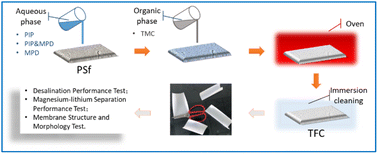
Polypiperazine amide composite NF membranes were prepared by interfacial polymerization. The porous polysulfone (PSf) substrate layer (molecular weight cut off is 50![[thin space (1/6-em)]](https://www.rsc.org/images/entities/char_2009.gif) 000, manufactured by the authors' company, preserved in 1 wt% sodium bisulfite aqueous solution) was fixed on the epoxy resin frame and immersed in deionized water. The aqueous phase was 5 wt% sodium phosphate (TSP) plus PIP or/and MPD, and the organic phase was 0.1 wt% TMC dissolved in n-hexane. The ambient temperature was 25 ± 1 °C.
000, manufactured by the authors' company, preserved in 1 wt% sodium bisulfite aqueous solution) was fixed on the epoxy resin frame and immersed in deionized water. The aqueous phase was 5 wt% sodium phosphate (TSP) plus PIP or/and MPD, and the organic phase was 0.1 wt% TMC dissolved in n-hexane. The ambient temperature was 25 ± 1 °C.
First, the moist porous PSf substrate layer was placed horizontally, and an 80 g aqueous solution was placed thereon for 60 s. Then, the excess solution was poured out and drained for 2–3 min. Next, 20 g organic phase solution was placed on the porous PSf substrate layer impregnated with aqueous phase for 10 s, and drained for 30 s.10 The frame and membrane were placed horizontally in an electric thermostat blast drying oven (DHG9140A, Shanghai Bluepard Instruments Co., Ltd) at 40 °C for 6 min. A series of NF membrane samples were prepared. These samples were immersed in deionized water for more than 12 hours, and then placed in a constant temperature and humidity chamber for more than 24 hours. Finally, they were packed into sealed bags for testing (Fig. 1).
Separation performance of TFC membranes
 | (1) |
 | (2) |
 | (3) |
Membrane structure and morphology test
Results and discussion
The optimal ratio of PIP and MPD
Our previous study was based on DOE design, and TFC membranes with specific properties were prepared with PIP and MPD.9 The interaction of five influencing factors on the two response variables, sodium chloride rejection (RNaCl) and pure water flux (J), of the TFC membranes were systematically analysed. The five influencing factors were the concentrations of two aqueous monomers (PIP and MPD), sodium phosphate (TSP), the organic monomer trimesoyl chloride (TMC), and the heating temperature (T) during interfacial polymerization. On this basis, the optimal aqueous and organic phase formulation and process conditions for preparing NF membrane by interfacial polymerization were obtained through data fitting, simultaneously, achieving high NaCl rejection and high water flux. Under the test condition of 0.5 MPa and 2000 ppm MgCl2, the prepared NF membrane displayed an average rejection rate (RMgCl2) of 94.1% (Fig. 2), which is comparable to that of some reported positively charged NF membranes that can be used to extract lithium from salt lakes.11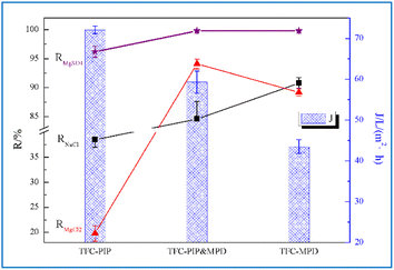 | ||
| Fig. 2 Magnesium–lithium separation performance of TFC membranes prepared with aqueous monomer PIP and/or MPD. | ||
Firstly, under the condition of 0.1% PIP concentration, the TFC membrane was prepared by PIP and MDP in the ratios of 1![[thin space (1/6-em)]](https://www.rsc.org/images/entities/char_2009.gif) :
:![[thin space (1/6-em)]](https://www.rsc.org/images/entities/char_2009.gif) 10, 1
10, 1![[thin space (1/6-em)]](https://www.rsc.org/images/entities/char_2009.gif) :
:![[thin space (1/6-em)]](https://www.rsc.org/images/entities/char_2009.gif) 5, 1
5, 1![[thin space (1/6-em)]](https://www.rsc.org/images/entities/char_2009.gif) :
:![[thin space (1/6-em)]](https://www.rsc.org/images/entities/char_2009.gif) 1, 5
1, 5![[thin space (1/6-em)]](https://www.rsc.org/images/entities/char_2009.gif) :
:![[thin space (1/6-em)]](https://www.rsc.org/images/entities/char_2009.gif) 1, and 10
1, and 10![[thin space (1/6-em)]](https://www.rsc.org/images/entities/char_2009.gif) :
:![[thin space (1/6-em)]](https://www.rsc.org/images/entities/char_2009.gif) 1, and the optimal ratio was determined by the magnesium–lithium separation performance test. Brine from Yiliping Salt Lake in Qinghai province of China was diluted 10 times as the inlet water solution. The test results are shown in Table 1.
1, and the optimal ratio was determined by the magnesium–lithium separation performance test. Brine from Yiliping Salt Lake in Qinghai province of China was diluted 10 times as the inlet water solution. The test results are shown in Table 1.
TFC prepared by (PIP![[thin space (1/6-em)]](https://www.rsc.org/images/entities/char_2009.gif) : :![[thin space (1/6-em)]](https://www.rsc.org/images/entities/char_2009.gif) MPD) MPD) |
Influent solution | CMg2+ (mg L−1) | CLi+ (mg L−1) | CLi+/CMg2+ | F |
|---|---|---|---|---|---|
11![[thin space (1/6-em)]](https://www.rsc.org/images/entities/char_2009.gif) 131.4 131.4 |
398.5 | 0.0358 | |||
10![[thin space (1/6-em)]](https://www.rsc.org/images/entities/char_2009.gif) : :![[thin space (1/6-em)]](https://www.rsc.org/images/entities/char_2009.gif) 1 1 |
Produced water | 1743 | 776.5 | 0.4455 | 12.44 |
5![[thin space (1/6-em)]](https://www.rsc.org/images/entities/char_2009.gif) : :![[thin space (1/6-em)]](https://www.rsc.org/images/entities/char_2009.gif) 1 1 |
Produced water | 1167 | 755.5 | 0.6474 | 18.08 |
1![[thin space (1/6-em)]](https://www.rsc.org/images/entities/char_2009.gif) : :![[thin space (1/6-em)]](https://www.rsc.org/images/entities/char_2009.gif) 1 1 |
Produced water | 662 | 761.4 | 1.1502 | 32.13 |
1![[thin space (1/6-em)]](https://www.rsc.org/images/entities/char_2009.gif) : :![[thin space (1/6-em)]](https://www.rsc.org/images/entities/char_2009.gif) 5 5 |
Produced water | 378.8 | 756.6 | 1.9974 | 55.79 |
1![[thin space (1/6-em)]](https://www.rsc.org/images/entities/char_2009.gif) : :![[thin space (1/6-em)]](https://www.rsc.org/images/entities/char_2009.gif) 10 10 |
Produced water | 277.2 | 448.5 | 1.6180 | 45.19 |
It can be clearly seen from Table 1 that in the range of 10![[thin space (1/6-em)]](https://www.rsc.org/images/entities/char_2009.gif) :
:![[thin space (1/6-em)]](https://www.rsc.org/images/entities/char_2009.gif) 1 to 1
1 to 1![[thin space (1/6-em)]](https://www.rsc.org/images/entities/char_2009.gif) :
:![[thin space (1/6-em)]](https://www.rsc.org/images/entities/char_2009.gif) 5, the increase of MPD concentration, in the produced water significantly decreases the magnesium ion concentration and slightly decreases the lithium-ion concentration, thus, gradually increasing the separation degree of magnesium and lithium. However, when the TFC membrane was prepared with PIP and MDP in the ratio of 1
5, the increase of MPD concentration, in the produced water significantly decreases the magnesium ion concentration and slightly decreases the lithium-ion concentration, thus, gradually increasing the separation degree of magnesium and lithium. However, when the TFC membrane was prepared with PIP and MDP in the ratio of 1![[thin space (1/6-em)]](https://www.rsc.org/images/entities/char_2009.gif) :
:![[thin space (1/6-em)]](https://www.rsc.org/images/entities/char_2009.gif) 10, the lithium-ion concentration was greatly reduced, which led to a decrease in the separation degree. It can be preliminarily concluded that the optimal magnesium–lithium separation efficiency was obtained at PIP
10, the lithium-ion concentration was greatly reduced, which led to a decrease in the separation degree. It can be preliminarily concluded that the optimal magnesium–lithium separation efficiency was obtained at PIP![[thin space (1/6-em)]](https://www.rsc.org/images/entities/char_2009.gif) :
:![[thin space (1/6-em)]](https://www.rsc.org/images/entities/char_2009.gif) MPD ratios of 1
MPD ratios of 1![[thin space (1/6-em)]](https://www.rsc.org/images/entities/char_2009.gif) :
:![[thin space (1/6-em)]](https://www.rsc.org/images/entities/char_2009.gif) 5–1
5–1![[thin space (1/6-em)]](https://www.rsc.org/images/entities/char_2009.gif) :
:![[thin space (1/6-em)]](https://www.rsc.org/images/entities/char_2009.gif) 10. In addition, combined with our previous study,9 by comparing the performances of salt retention and water flux of the prepared composite membrane the optimal ratio of PIP
10. In addition, combined with our previous study,9 by comparing the performances of salt retention and water flux of the prepared composite membrane the optimal ratio of PIP![[thin space (1/6-em)]](https://www.rsc.org/images/entities/char_2009.gif) :
:![[thin space (1/6-em)]](https://www.rsc.org/images/entities/char_2009.gif) MPD was set as 1
MPD was set as 1![[thin space (1/6-em)]](https://www.rsc.org/images/entities/char_2009.gif) :
:![[thin space (1/6-em)]](https://www.rsc.org/images/entities/char_2009.gif) 9, and the magnesium–lithium separation performance for salt lake brine is shown in Table 2, which was the best observed in this study.
9, and the magnesium–lithium separation performance for salt lake brine is shown in Table 2, which was the best observed in this study.
| CMg2+ (mg L−1) | CLi+ (mg L−1) | CLi+/CMg2+ | F | |
|---|---|---|---|---|
| Influent solution | 11![[thin space (1/6-em)]](https://www.rsc.org/images/entities/char_2009.gif) 131.4 131.4 |
398.5 | 0.0358 | |
| Produced water of TFC-PIP | 2011.5 | 877.2 | 0.4361 | 12.18 |
| Produced water of TFC-PIP & MPD | 166.1 | 781.1 | 4.7026 | 131.36 |
| Produced water of TFC-MPD | 68.5 | 297.9 | 4.3489 | 121.48 |
The performance of TFC membranes prepared with PIP and/or MPD
For a direct comparison of structure and performance, a series of TFC membranes using PIP and/or MPD as aqueous monomers were prepared under the same conditions. Specifically, under the conditions of 5 wt% TSP in the aqueous phase, 0.1 wt% TMC dissolved in n-hexane, and oven temperature of 40 °C, the TFC prepared with the PIP concentration of 0.1 wt% was labelled as TFC-PIP; the TFC prepared with MPD concentration of 0.9 wt% was labelled as TFC-MPD; and the TFC prepared with PIP concentration of 0.1 wt% and MPD concentration of 0.9 wt% was labelled as TFC-PIP & MPD. Their rejection performance for NaCl, MgCl2, and MgSO4, as well as their pure water flux values were first compared, and the data are shown in Fig. 2.TFC-PIP exhibited the typical separation characteristics of NF membranes, RMgSO4 > RNaCl > RMgCl2. This is due to the hydrolysis of a large number of acyl chloride groups in the poly(piperazine-amide) membrane structure to form negative charges, which hinder the permeation of anions, especially high-valence ions, by virtue of the charge effect.12 In the MgSO4 solution, due to their large space volume, the divalent SO42− ions are basically unable to permeate the membrane. Meanwhile, to maintain the charge balance, the divalent Mg2+ ions are kept on the water inlet side, resulting in a rejection rate of 96.2%. In the NaCl system, Cl− is rejected by a small portion due to a relatively weak charge effect, resulting in RNaCl at 38.5%. In the MgCl2 system, the divalent Mg2+ ions shield the charge effect formed by the anions, allowing a higher permeation ratio of Cl− than that in the NaCl system. Meanwhile, Mg2+ combines more Cl− ions to permeate the membrane. Therefore, RMgCl2 is the lowest at 19.8% among the rejection rates for the three systems. TFC-MPD displayed typical separation characteristics of reverse osmosis (RO) membranes, RMgSO4 > RNaCl ≈ RMgCl2. The separation is mainly achieved through the sieving effect, i.e., water molecules and small ions are allowed to pass through, while large ions are rejected. Therefore, RMgSO4 is the highest at 99.8%. The salts in the NaCl and MgCl2 systems were also mostly rejected. However, the MPD reaction concentration set in this study was only 0.9%, which is much lower than the monomer concentrations reported for the preparation of reverse osmosis (RO) membranes,13 leaving defective structure causing partial salt penetration. This is reflected in the RNaCl value of only 90.8%. On the other hand, the osmotic pressure of the MgCl2 system is higher than that of NaCl, and water is slightly less permeated, which is reflected in a higher concentration of the permeated solution and a slightly lower rejection rate at 89.2% (RMgCl2). It has been suggested that the addition of a very small amount of MPD to the aqueous phase system of PIP can alter the membrane performance.14 As shown in Fig. 2, TFC-PIP & MPD exhibited altered separation performance for the three salts in comparison to the other two TFC membranes, with RMgCl2 being the highest at 94.1%. RNaCl and J for TFC-PIP & MPD follow the same trend, being lower than that of TFC-MPD but much greater than that of TFC-PIP. Meanwhile, RMgSO4 for TFC-PIP & MPD is very high, which is comparable to that of TFC-MPD. Overall, the sieving size in the TFC-PIP & MPD structure should be between that of the other two membranes, with a force that hinders the permeation of Mg2+ ions, resulting in a larger RMgCl2 and RMgSO4 than that of TFC-MPD and TFC-PIP, respectively. Considering the possible presence of both positive and negative charge effects, the permeation rate of NaCl is not too high either, with RNaCl being 84.6%.
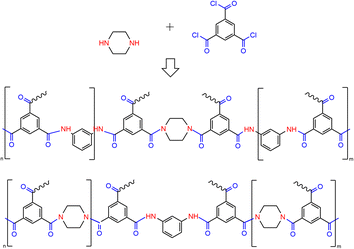
Water fluxes of the three TFC membranes follow the sequence JTFC-PIP > JTFC-PIP & MPD > JTFC-MPD. The water flux of TFC-MPD is attributed to its low hydrophilicity and restricted chain flexibility. The benzene rings in the fully aromatic polyamide produced from the reaction of MPD and TMC present a planar structure, as shown in the reaction eqn (4).
 | (4) |
The dense stacking of layers leads to the compression of water channels. Moreover, amino hydrogens in the structure form hydrogen bonds, reducing the size of water channels and thus leading to low flux and high rejection.15 The poly(piperazine-amide) formed from the reaction of PIP and TMC is different. PIP has a chair conformation, and thus form macromolecules with large free volume via polymerization with TMC. In addition, the structure is free from amino hydrogens, and no hydrogen bonds can be formed. Therefore, the permeation efficiency of water and low-valent ions is much greater than that of TFC-MPD. The performance of TFC-PIP & MPD is in-between, which will be discussed subsequently in conjunction with the analysis of its structural characteristics.
Magnesium–lithium separation performance of TFC membranes prepared with PIP and/or MPD
In this study, TFC-PIP and TFC-MPD were still used for comparison. Under the same conditions, brine from Yiliping Salt Lake in Qinghai diluted 10 times was used as the inlet aqueous solution. The concentration of Mg2+ (CMg2+) was 11![[thin space (1/6-em)]](https://www.rsc.org/images/entities/char_2009.gif) 131.4 mg L−1 and that of Li+ (CLi+) was 397.5 mg L−1, with a magnesium–lithium ratio (CMg2+/CLi+) of 28. In addition, there are SO42− and Cl− at around 3000 and 35
131.4 mg L−1 and that of Li+ (CLi+) was 397.5 mg L−1, with a magnesium–lithium ratio (CMg2+/CLi+) of 28. In addition, there are SO42− and Cl− at around 3000 and 35![[thin space (1/6-em)]](https://www.rsc.org/images/entities/char_2009.gif) 000 mg L−1, respectively, and a small number of other cations including Na+ and K+ in the test water. The complex composition may have an impact on the magnesium–lithium separation performance of the membranes. In Table 2, the Mg2+ and Li+ concentrations in the final produced water of these TFC membranes differ greatly, indicating the distinctly divergent magnesium–lithium separation performance of the membranes in salt-lake brine.
000 mg L−1, respectively, and a small number of other cations including Na+ and K+ in the test water. The complex composition may have an impact on the magnesium–lithium separation performance of the membranes. In Table 2, the Mg2+ and Li+ concentrations in the final produced water of these TFC membranes differ greatly, indicating the distinctly divergent magnesium–lithium separation performance of the membranes in salt-lake brine.
Based on the data presented in Table 2, the rejection of Mg2+ (RMg2+) and Li+ (RLi+) in salt-lake brine was calculated for the TFC membranes using eqn (2), and the results are shown in Fig. 3A. The final produced water of TFC-PIP has the highest concentration of Mg2+, with a rejection rate of only 81.93%. Despite the compression of water channels under complex high-concentration influent and high-pressure conditions, which leads to the rejection of most divalent ions, especially SO42−, in the influent, the high concentration of Mg2+ in the influent shields the charge effect of the membrane and a large number of monovalent ions carry some Mg2+ through the membrane. To maintain the charge balance, Cl− on the produced water side drives more Li+ to permeate, resulting in the negative rejection of Li+ with RLi+ being −120.1%. The final produced water of TFC-MPD has the lowest concentrations of Mg2+ and Li+, which is attributed to the sieving effect that basically rejects both ions, with RMg2+ being 99.38%. The hydration diameters of Mg2+ and Li+ are 0.856 and 0.764 nm, respectively, and Li+ ions are more easily driven by Cl− on the produced water side to permeate the membrane, thus RLi+ is lower than RMg2+ at 25.24%. The concentrations of Mg2+ and Li+ in the final produced water of TFC-PIP & MPD were both between the above membranes. Specifically, in the produced water, CMg2+ was only 166.1 mg L−1, which is much lower than that achieved using TFC-PIP. This verified the analysis discussed in Section 2.1, i.e., the presence of positive charges in TFC-PIP & MPD affects the permeation of divalent cations, contributing to RMg2+ of 98.51%. However, being different from the performance of TFC-MPD, TFC-PIP & MPD displayed negative rejection of Li+ with an RLi+ value of −96.01%, which indicates that the sieving size of the membrane structure was larger than the hydration diameter of Li+.
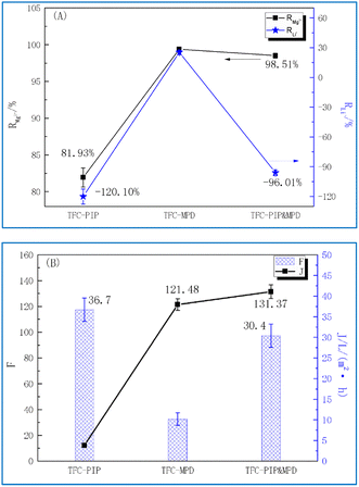 | ||
| Fig. 3 Magnesium–lithium separation performance of TFC membranes prepared with PIP and/or MPD: (A) salts rejection rate Rj, (B) separation ratio of magnesium–lithium (F) and flux (J). | ||
The separation ratios of magnesium–lithium (F) were calculated for the membranes using eqn (3), and the corresponding separation efficiency were analysed comprehensively combining water fluxes (J) of the membranes. The results are shown in Fig. 3B. Despite the highest JTFC-PIP at 36.7 L (m−2 h−1), FTFC-PIP was the lowest at 12.18. This is because more Mg2+ ions permeated to the produced water side and magnesium–lithium separation was thus not achieved. There were almost no Mg2+ ions in the produced water of TFC-MPD, which means an ideal magnesium–lithium separation, with an FTFC-MPD value of 121.4. However, the JTFC-MPD was only 10.2 L (m−2 h−1), indicating a low separation efficiency. In comparison, FTFC-PIP & MPD is the largest at 131.37, which is attributed to the membrane's high rejection rate of Mg2+ and negative rejection of Li+ ions. Meanwhile, the flux can reach 30.4 L (m−2 h−1). Both factors make TFC-PIP & MPD the ideal candidates among the three membranes in terms of magnesium–lithium separation efficiency. Subsequent structural and surface morphology tests of the TFC membranes were carried out to further analyse the relationship between their separation performance and structural characteristics.
Membrane structure and morphology
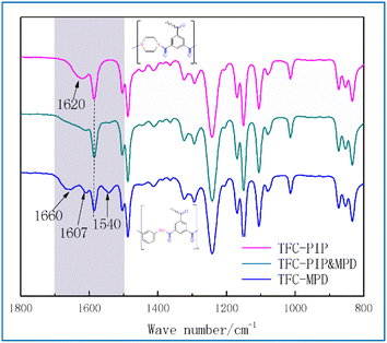
Fig. 4 shows the ATR-FTIR absorption spectra of the TFC membranes. The absorption peak of the polysulfone phenylene ether groups (Ar–O–Ar, 1240 cm−1) in the substrate was selected as the internal standard, and the spectra were normalized.16 The range of 800–1800 cm−1 was regarded as the characteristic region of the polyamide.17 Differences in the positions and shapes of characteristic peaks in the range of 1500–1700 cm−1 were clearly identified for these TFC membranes.The main chain of the polyamide prepared by interfacial polymerization of MPD and TMC consists of an amide group with two alternate benzene rings, featuring fully aromatic polyamide, as shown in eqn (4). In the TFC-MPD spectrum (Fig. 4), the peaks at 1660 and 1540 cm−1 mainly belonged to the amide II absorption, corresponding to the vibrational absorption of the C![[double bond, length as m-dash]](https://www.rsc.org/images/entities/char_e001.gif) O and N–H bonds in amide, respectively. Meanwhile, the absorption peaks of benzene rings in MPD and TMC are located at 1607 and 1580 cm−1, respectively.18 The main chain of the poly(piperazine-amide) prepared by interfacial polymerization of PIP and TMC consists of an amide group and a benzene ring alternately, as shown in eqn (5).
O and N–H bonds in amide, respectively. Meanwhile, the absorption peaks of benzene rings in MPD and TMC are located at 1607 and 1580 cm−1, respectively.18 The main chain of the poly(piperazine-amide) prepared by interfacial polymerization of PIP and TMC consists of an amide group and a benzene ring alternately, as shown in eqn (5).
 | (5) |
In the TFC-PIP spectrum (Fig. 4), the absorption peak of benzene ring is at 1580 cm−1. However, instead of the rigid benzene structure of MPD, PIP has a steric chair conformation which results in the looser structure of poly(piperazine-amide) than fully aromatic polyamide, and the conjugation between the benzene ring and the P electrons on the amide can be fully reflected. Therefore, in the TFC-PIP spectrum (Fig. 4), the absorption peaks of Amide II and benzene ring interact with each other, giving rise to the peak of Amide II at 1620 cm−1. PIP is a secondary diamine and poly(piperazine-amide) is a tertiary amine, so there is no peak corresponding to the N–H bond around 1540 cm−1.
In the TFC-MPD and PIP spectra (Fig. 4), the absorption peaks of the two benzene rings at 1607 and 1580 cm−1 were the same as those of TFC-MPD. However, there was a weak broad peak in the range of 1660–1607 cm−1, and the intensity of the peak at 1540 cm−1 was also obviously weaker and even unrecognizable. It was deduced that both PIP and MPD participated in the polymerization reaction to form a complex polyamide structure, as shown in Fig. 5. On the one hand, the incorporation of variable spatial conformations between regularly arranged benzene ring layers in the fully aromatic polyamide molecules disrupts the tight interlayer structure and weakens the hydrogen bonds of the amino hydrogens. On the other hand, the addition of rigid planar benzene rings to the poly(piperazine amide)-dominated structure leads to the formation of a more dense network structure. These interactions weaken the characteristic absorption of single molecular bonds, and the amide II structure does not show characteristic vibrational peaks over a wide range due to the enhanced conjugation of the amide and the benzene ring.
XPS can quantitatively analyse the structural composition of the membrane surface. However, the XPS electron energy has a maximum analysis depth of only 10 nm,19 which cannot penetrate the entire separation layer of the heterogeneous composite membrane, so only differences in the structural composition at the same depth of the surface layer of the membrane can be analysed. Theoretically, if all three substituents of TMC are bonded to PIP or MPD monomer to form amide bonds in the interfacial polymerization process, the O/N molar ratio will be 1 in the prepared membrane structure. Obviously, the TFC-PIP sample in Table 3 is close to this ratio. However, as mentioned above, it is generally believed that there are more unreacted acyl chloride groups on the surface of the composite membrane, which are hydrolysed to form carboxyl groups, resulting in an O/N ratio greater than 1. If only one of the TMC substituents binds to form an amide group, and the other two are hydrolysed to form a carboxyl group, the O/N ratio is close to 5. Obviously, the O/N ratio of the TFC-PIP & MPD sample in Table 3 is the highest, which may be because it has the highest concentration of aqueous monomers among the three composite membrane samples, and the surface layer of the prepared composite membrane has the highest hydrolysis of acyl chloride groups within the thickness range of XPS detection.
| Sample ID | C (%) | O (%) | N (%) | O/N |
|---|---|---|---|---|
| TFC-PIP | 70.80 | 16.57 | 12.64 | 1.31 |
| TFC-PIP & MPD | 72.65 | 23.13 | 5.12 | 4.52 |
| TFC-MPD | 75.59 | 15.09 | 3.65 | 4.13 |
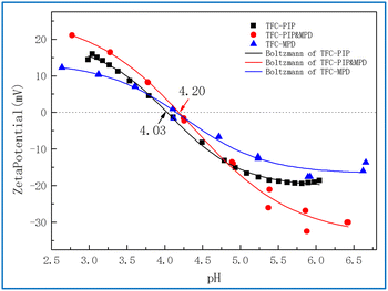
Fig. 6 shows the zeta potential curves of the membranes with pH. Obviously, all three composite membranes were negatively charged at neutral pH, and the isoelectric point of TFC-PIP was the lowest (4.03), while the other two films had a very close isoelectric point of around 4.20. In the neutral pH range above the isoelectric point, the absolute value of the zeta potential of TFC-PIP & MPD was the highest, representing the largest surface charge density,20 which is consistent with the analysis results of XPS.
Under the neutral condition of pH > 6, the zeta potential values of TFC-PIP and TFC-MPD were similar, but the O/N value of TFC-MPD in XPS was much larger than that of TFC-PIP. This may be due to the thick separation layer of TFC-MPD, and the detection depth of XPS was only analysed to the relatively loose hydrolysis layer on the surface. In contrast, the separation layer of TFC-PIP was relatively thin, and the detection depth of XPS involved the cross-linking layer with a high cross-linking degree.
Fig. 7 shows the surface morphologies of membranes prepared with different aqueous monomers. Among them, (A) is the PSf substrate layer, featured by a smooth surface with uniform distribution of pattern and occasional gaps of about 10 nm in size. (B) Is TFC-PIP, with a typical particle morphology of poly(piperazine-amide). The particle size was in the range of 80–120 nm, with clear particle boundaries, presenting a smooth surface. (D) Is TFC-MPD, with a leaf-like morphology. The ‘leaves’ varied in size and were partially interconnected, forming a complex three-dimensional structure. The “leaves” closer to the substrate were smaller in size with different heights. The overall surface was rough. (C) Shows the surface of TFC-PIP and MPD, which varied distinctly from (B) and (D), with two particle sizes. Particles on the surface were large with a diameter >150 nm and sparsely distributed with clear boundaries between each other.
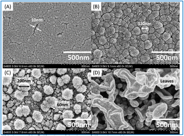 | ||
Fig. 7 SEM images ((A) PSf substrate, (B) TFC-PIP, (C) TFC-PIP & MPD, and (D) TFC-MPD) under 800![[thin space (1/6-em)]](https://www.rsc.org/images/entities/char_2009.gif) 00× magnification with the working distance of 8.9 mm. 00× magnification with the working distance of 8.9 mm. | ||
Particles in the lower layers close to the substrate were very small with a diameter <50 nm. Their distribution follows the texture of the substrate, suggesting particles cover the substrate evenly. This is different from the morphologies reported for membranes prepared by interfacial polymerization of MPD and PIP with TMC,21 which may be due to the differences in characteristics of the substrate, monomer concentration, and interfacial polymerization temperature.22
Interfacial polymerization processes of different monomers and structure–performance mechanism of TFC membranes
The current industrial process of TFC membranes is interfacial polymerization. It allows easy adjustment of the composition and thickness of the membrane, and the aqueous monomer can directly determine the performance of membranes. MPD is the classic aqueous monomer for RO membrane preparation, and PIP is the classic aqueous monomer for NF membranes. With the rapid diffusion of aqueous monomers into the organic phase, interfacial polymerization occurs, and the initial polyamide in turn inhibits the diffusion of monomers simultaneously. This is a self-inhibiting process, and the polyamide structure traces the diffusion of aqueous monomers to some extent.23 On this basis, combining the above results, the associations between interfacial polymerization processes of different monomers and the structure/morphology of membranes are discussed, as shown in Fig. 8.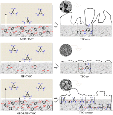 | ||
| Fig. 8 Schematic of the associations between the interfacial polymerization processes using PIP and/or MPD and the structure/morphology of the TFC membranes. | ||
It has been suggested that the partition coefficient of MPD is much higher than that of PIP,24 i.e., MPD diffuses more quickly to polymerize with TMC and forms a fully aromatic polyamide with rigid molecular chains. This results in a thick layer with leaf-like surface morphology and compact structure, as presented in this paper for TFC-MPD. It mainly relies on the sieving effect for desalination but is not efficient for water permeation. On the other hand, PIP with chair conformation polymerizes with TMC to produce poly(piperazine-amide) with loose structure and particle surface morphology. It mainly relies on the charge effect to reject high-valence ions of the same charge and allows efficient permeation of monovalent ions and water. TFC-PIP is thinner than TFC-MPD, suggesting that poly(piperazine-amide) has a stronger diffusion inhibition ability than fully aromatic polyamide. It has been reported that, with both MPD and PIP in the aqueous phase, acid receptors inhibit the interfacial diffusion of MPD to reduce its partition coefficient, while increasing the reaction rate of PIP.25 As seen from the FTIR spectrum in Fig. 4, it is confirmed that both aqueous monomers are involved in the formation of polyamide under the conditions set in this study. On the surface of TFC-PIP & MPD, the fine particles covering the substrate are mainly poly(piperazine-amide). Although MPD diffuses faster than PIP, TSP accelerates the formation of initial poly(piperazine-amide), which immediately inhibits further diffusion of most MPD and PIP. The excess of amine monomers results in a large amount of unreacted amino groups in the polyamide structure close to the substrate, which hydrolyses to form a positive charge. Prior to this, the escaped MPD polymerizes with TMC to form the initial fully aromatic polyamide, which has a low degree of polymerization. The fully aromatic polyamide particles, as nucleation sites, promote the diffusion of the two monomers for further reaction and cut particles of the covering. Similarly, the MPD will diffuse and polymerize rapidly, while the initial poly(piperazine-amide) inhibits the diffusion simultaneously. The diffusion and inhibition compete, and the surface morphology of TFC-PIP and MPD eventually showed sporadic distribution of large particles. Due to the excess of TMC in the final reaction, a large number of acyl chloride groups are located on the outermost of the membrane and hydrolyses to form negative charges.
In summary, the structure of TFC-PIP & MPD contains both positive and negative charges, which blocks the permeation of Mg2+ions. Due to the involvement of PIP in the structure formation, the membrane has a looser structure than fully aromatic polyamide, allowing the permeation of Li+ ions and thus achieving negative rejection of Li+ in the diluted salt-lake brine. Therefore, the efficient separation of Mg2+ and Li+ is enabled. On the other hand, the involvement of MPD in the process equips the membrane with a denser structure than that of poly(piperazine-amide), which improves desalination. This is conducive to lithium extraction from salt-lake brines. The fine particles formed at the nucleation sites and the loose internal structure provide abundant water channels for the efficient separation of magnesium–lithium by the TFC.
Conclusions
To optimize the ratio of PIP and MPD in TFC membrane preparation, we conducted additional control experiments examining the performance of TFC membranes with varying ratios of PIP and MPD (ranging from 10![[thin space (1/6-em)]](https://www.rsc.org/images/entities/char_2009.gif) :
:![[thin space (1/6-em)]](https://www.rsc.org/images/entities/char_2009.gif) 1 to 1
1 to 1![[thin space (1/6-em)]](https://www.rsc.org/images/entities/char_2009.gif) :
:![[thin space (1/6-em)]](https://www.rsc.org/images/entities/char_2009.gif) 10) in the brine from Yiliping Salt Lake. Through analysis and comparison, the optimal ratio is given. When the prepared NF was used in magnesium–lithium separation in salt-lake brine (magnesium–lithium ratio of 28), the rejection rates of Mg2+ and Li+ ions are 98.51% and −96.01%, respectively, and the water flux is 30.4 L (m−2 h−1), achieving highly efficient magnesium–lithium separation. Via characterization tests, the separation performance, structure, and surface morphology of TFC-MPD&PIP are determined to be different from those of TFC-PIP and TFC-MPD. It is suggested that both PIP and MPD are involved in the formation of polyamide structures in this study. Due to the different partition coefficients and polymerization characteristics of aqueous monomers, the formed membrane has a specific molecular composition and spatial structure, which effectively hinder the permeation of Mg2+ via charge effect, but facilitate the permeation of Li+ and water molecules during the separation process of salt-lake brines.
10) in the brine from Yiliping Salt Lake. Through analysis and comparison, the optimal ratio is given. When the prepared NF was used in magnesium–lithium separation in salt-lake brine (magnesium–lithium ratio of 28), the rejection rates of Mg2+ and Li+ ions are 98.51% and −96.01%, respectively, and the water flux is 30.4 L (m−2 h−1), achieving highly efficient magnesium–lithium separation. Via characterization tests, the separation performance, structure, and surface morphology of TFC-MPD&PIP are determined to be different from those of TFC-PIP and TFC-MPD. It is suggested that both PIP and MPD are involved in the formation of polyamide structures in this study. Due to the different partition coefficients and polymerization characteristics of aqueous monomers, the formed membrane has a specific molecular composition and spatial structure, which effectively hinder the permeation of Mg2+ via charge effect, but facilitate the permeation of Li+ and water molecules during the separation process of salt-lake brines.
Author contributions
Cheng Xin: methodology, investigation, formal analysis, and writing; Pan Qiaoming: methodology, conceptualization, funding acquisition, and supervision; Tan Huifen: project administration and validation; Chen Keke: visualization; Liu Wenchao: resource; Shi Yingying: data curation; Du Shengyu: resources; Zhu Baoku: funding acquisition.Conflicts of interest
There are no conflicts to declare.Acknowledgements
This work was supported by the National Key Research and Development Program of China (No. 2021YFB3801100); the Key research and Development Project of Zhejiang Province (No. 2021C01173) and Zhejiang Key Laboratory of Seawater Desalination Technology Research (No. 2012E10001).References
- J. H. Han, Z. Nei and C. H. Fang, et al., Inorg. Chem. Ind., 2021, 53, 61 Search PubMed.
- C. X. Jang, B. L. Chen and D. J. Zhang, et al., CIESC J., 2022, 73, 481 Search PubMed.
- A. I. Schfer, T. D. Waite and A. G. Fane, Nanofiltration: Principles and Applications, Elsevier, Britain, 2003 Search PubMed.
- P. Xu, W. Wang and X. Qian, et al., Desalination, 2019, 449, 57 CrossRef CAS.
- H. X. Ye, Y. H. Chen and Y. Chen, et al., Chem. Ind. Eng. Prog., 2023, 42, 1934–1943 Search PubMed.
- Y. Zhang, L. Wang and W. Sun, et al., J. Ind. Eng. Chem., 2020, 81, 7–23 CrossRef CAS.
- Q. Zhao, and H. W. Peng, Chinese Pat., 202111012991.1, 2021.
- Q. M. Pan, W. Wang and J. Y. Qi, et al., Chem. Prod. Technol., 2014, 21, 4 Search PubMed.
- X. Cheng, Q. M. Pan and H. F. Tan, et al., Technol. Water Treat., 2023, 49, 73–78 Search PubMed.
- X. Cheng, Q. M. Pan and T. Liu, et al., J. Appl. Polym. Sci., 2020, 137, 48284 CrossRef CAS.
- H. X. Ye, Y. H. Chen and Y. Chen, Chem. Ind. Eng. Prog., 2023, 42(4), 1934–1943 Search PubMed.
- R. Epsztein, E. Shaulsky and N. Dizge, et al., Environ. Sci. Technol., 2018, 52, 4108 CrossRef CAS PubMed.
- J. E. Cadotte, R. J. Petersen and R. E. Larson, et al., Desalination, 1980, 32, 25 CrossRef.
- J. J. Li, X. Y. Yue and J. F. Tao, et al., Technol. Water Treat., 2014, 40, 59 CrossRef CAS.
- W. J. Lau, A. F. Ismail and N. Misdan, et al., Desalination, 2012, 287, 190 CrossRef CAS.
- J. J. Li, T. Chen and Y. Liu, et al., Membr. Sci. Technol., 2018, 38(06), 1–7 CAS.
- H. F. Tan, J. J. Li and X. Y. Yue, et al., Membr. Sci. Technol., 2015, 35, 22 CAS.
- Z. X. Zhang, Handbook of Polymer Material Analysis, Chemical Industry Press, Beijing, 2016 Search PubMed.
- F. W. John and W. John, Watts An introduction to surface analysis by XPS and AES, Huadong Chemical Industrial Institute Press, Shanghai, 2008 Search PubMed.
- J. Luo and Y. Wan, J. Membr. Sci., 2013, 438, 18–28 CrossRef CAS.
- N. K. Saha and S. V. Joshi, J. Membr. Sci., 2009, 342, 60 CrossRef CAS.
- Z. M. Zhan, Z. L. Xu and K. K. Zhu, et al., J. Membr. Sci., 2020, 604, 118067 CrossRef CAS.
- Z. Tan, S. F. Chen and X. S. Peng, et al., Science, 2018, 360, 518 CrossRef CAS PubMed.
- C. A. Orr, J. J. Cernohous and P. Guegan, et al., Polymer, 2001, 42, 8171 CrossRef CAS.
- I. C. Kim, J. Jegal and K. H. Lee, J. Polym. Sci., Part B: Polym. Phys., 2002, 40, 2151 CrossRef CAS.
| This journal is © The Royal Society of Chemistry 2023 |

