
 Open Access Article
 This Open Access Article is licensed under a Creative Commons Attribution-Non Commercial 3.0 Unported Licence
Extraction of alumina and silica from high-silica bauxite by sintering with sodium carbonate followed by two-step leaching with water and sulfuric acid
Yue Sun a,
Aifang Pan*ab,
Yuzhao Ma*c and
Jie Changc
a,
Aifang Pan*ab,
Yuzhao Ma*c and
Jie Changc
aSchool of Earth Science and Resources, Chang'an University, Xi'an 710054, China. E-mail: panaifang@126.com
bInstitute for Interdisciplinary and Innovate Research, Xi'an University of Architecture and Technology, Xi'an 710055, China
cCollege of Materials Science and Engineering, Xi'an University of Architecture and Technology, Xi'an 710055, China. E-mail: yuzhaoma@126.com
First published on 2nd August 2023
Abstract
Efficient utilization of high-silica bauxite and minimization of bauxite residue are of great significance for the sustainable development of the alumina industry. In this paper, a novel process is proposed to extract Al2O3 and SiO2 from high-silica bauxite without residue discharge, that is, sintering bauxite with Na2CO3 followed by two-step leaching with water and sulfuric acid. The effects of the sintering parameters on the process were investigated, and the phase transformations during sintering and leaching were revealed by using phase diagram, thermogravimetric analysis (TGA) and differential scanning calorimetric (DSC), X-ray diffraction (XRD), scanning electron microscopy (SEM) and energy dispersive spectrometer (EDS) methods. When the mixture of the high-silica bauxite and Na2CO3 with mole ratio of Na2O/(Al2O3 + SiO2) of 1 was sintered at 950 °C for 30 min, diaspore and kaolinite were primarily converted into Na1.95Al1.95Si0.05O4 and an amorphous phase, respectively. In the water leaching process, Na1.95Al1.95Si0.05O4 was dissolved while the amorphous phase underwent some transformations to form the water leaching residue, resulting in ∼84% of Al2O3 being extracted for alumina production. In the sulfuric acid leaching process, the amorphous phase in the water leaching residue dissolved, resulting in ∼13% of Al2O3 and ∼86% of SiO2 being extracted for the production of polyaluminium ferric sulfate (PAFS) and silica gel, respectively. The silica gel had a high purity, containing more than 88% of SiO2 after drying.
1 Introduction
Silica is a major impurity in bauxite ores, which is commonly present as quartz (SiO2) and phyllosilicate minerals such as kaolinite (Al4[Si4O10](OH)8), illite (KxAl4Si8−xAlxO20(OH)2) and pyrophyllite (Al2[Si4O10](OH)2).1,2 When producing alumina from bauxite using the Bayer process, the reactive silica is transformed into insoluble sodium aluminosilicate hydrate known as desilication product (DSP), resulting in a severe loss of alumina and caustic soda.3–5 As a result, high-silica bauxite, in which reactive silica is above ∼8%, cannot be economically processed by the conventional Bayer process.2 With the increase of alumina production, high-grade bauxite is rapidly consumed, leading to an increase in the proportion of high-silica bauxite. Efficient development and utilization of high-silica bauxite has become an urgent and significant challenge for the alumina industry.Many methods have been developed to extract alumina from high-silica bauxite, which can be broadly classified into four main categories, as shown in Table 1. Among these methods, most are at the experimental stage and only a few have been applied industrially. The flotation-Bayer process has been widely applied in the alumina refineries, but it introduces large amounts of hazardous organic reagents and produces tailings totaling of about 25% of the initial bauxite ores in weight.25,26 The lime Bayer process has been also employed to process a portion of high-silica bauxite, but it cannot economically process the bauxite with a mass ratio of alumina to silica (A/S) lower than 5.7 For processing high-silica bauxites with A/S < 5, the lime-soda sintering process and its various combinations with the Bayer process are the preferred choice.27 However, they are barely economically viable due to the high operating costs. In addition, the extraction of silica is rarely considered by the methods listed in Table 1. Only in the chemical beneficiation of high-silica bauxite, silica is extracted into alkali solutions and is used to produce silicate products such as 4A zeolite.28,29 In other methods, silica is left in the bauxite residue.
| Category | Description | Limitation | Method | Development stage |
|---|---|---|---|---|
| Pre-desilication of high-silica bauxite followed by the Bayer process | Improving the A/S of high-silica bauxite by physical, chemical and biological beneficiation methods to meet the requirement of the Bayer process | Physical beneficiation discharges a lot of tailings, wasting serious resources. Chemical beneficiation is difficult in recycling desilication solutions and high in production costs. Biological beneficiation has a long processing period and an unstable desilication efficiency | Flotation6 | Industrial application |
| Alkali leaching7 | Experimental stage | |||
| Roasting-alkali leaching8 | Experimental stage | |||
| Reduction roasting-alkali leaching9 | Experimental stage | |||
| Biological desilication10 | Experimental stage | |||
| The Bayer process variations | Converting the reactive silica into hydrogarnet or calcium silicate by adding lime and adjusting digestion conditions, resulting in a lower loss of caustic soda | Adding large amount of lime increases the burden of solid–liquid separation and the sodium carbonate content in sodium aluminate solution. Increasing alkali concentration leads to a difficult solid–liquid separation and a greater evaporation energy consumption | The lime Bayer process11 | Industrial application |
| The calcification–carbonization process12 | Experimental stage | |||
| The hydro-chemical process13 | Experimental stage | |||
| The sub-molten salt process14 | Experimental stage | |||
| Sintering processes | Converting silica into insoluble dicalcium silicate during sintering and separating it with soluble sodium (or calcium) aluminate during leaching | Sintering processes are high in energy consumption and poor in economic efficiency | The lime-soda sintering process15 | Industrial application |
| The lime-soda sintering process variations16,17 | Experimental stage | |||
| The lime sintering process18 | Stop production after application | |||
| Acid methods | Processing bauxite with acid or ammonium salt to get aluminum salt solution and leaving silica in the residue | Acid has a serious corrosion on equipment, while ammonium salt has a potential ammonia leak. In addition, impurities in aluminum salt solutions are difficult and costly to remove | Ammonium sulfate roasting-water leaching19,20 | Experimental stage |
| Acid leaching21–23 | Experimental stage | |||
| Thermal or mechanical activation-acid leaching24 | Experimental stage |
Bauxite residue is a solid waste left over after extracting alumina from bauxite. When high-silica bauxite is used as a feedstock for alumina production, more bauxite residue is discharged compared to processing high-grade bauxite.30 At present, most bauxite residues are sent to dams for storage, taking up large amounts of land and incurring significant costs for the construction and maintenance of the dams.31,32 In addition, long-time storage of bauxite residue poses a potential threat to the surrounding environment and may cause safety accidents such as leakage and dam failure.33 Therefore, minimization and recycling of bauxite residue should be considered in the production of alumina. However, the alkali methods listed in Table 1 rarely take this aspect into account. Only the calcification–carbonization process proposed to recycle bauxite residue for preparing cement.34 Compared with the alkali methods, the acid methods produce less residue which is highly enriched in silica and can be used as a raw material for inorganic silica products.19,23
Alkali methods are well established in the production of alumina, while acid methods have advantages in the minimization and recycling of bauxite residue. Therefore, an attempt can be made to combine the alkali and acid methods. In our previous studies, a novel combined alkali-acid process was proposed to extract aluminum, silicon and iron from silver tailings.35,36 In the present study, the process was adapted to realize the extraction of Al2O3 and SiO2 from high-silica bauxite without residue discharge, as shown in Fig. 1. First, high-silica bauxite is activated by sintering with Na2CO3. Second, water leaching is conducted at atmospheric pressure to extract most of Al2O3 from the sintered sample into the sodium aluminate solution, which can be used to produce alumina by desilication, carbonation decomposition and calcination. Third, sulfuric acid leaching is conducted at atmospheric pressure to extract SiO2 and the remaining Al2O3 from the water leaching residue into the acid leaching solution, which can be used to produce silica gel and polyaluminium ferric sulfate (PAFS) by aging, separation, concentration and polymerization. This study aims to investigate the effects of sintering temperature (850–1050 °C), sintering time (10–50 min) and the mole ratio of Na2O/(Al2O3 + SiO2) (0.6–1.4) on the extraction of Al2O3 and SiO2, and to reveal the process mechanism using phase diagram, thermogravimetric analysis (TGA) and differential scanning calorimetric (DSC), X-ray diffraction (XRD), scanning electron microscope (SEM) and energy dispersive spectrometer (EDS) techniques.
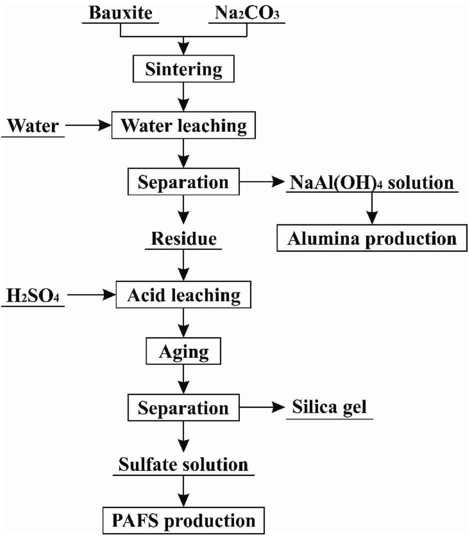 | ||
| Fig. 1 Flowsheet for extraction of alumina and silica from high-silica bauxite. | ||
2 Experimental
2.1 Raw materials
The high-silica bauxite sample used in this study had been described in our previous study, which has a high Al2O3 content of 62.92%, a high SiO2 content of 16.72%, a low A/S of 3.76, and a mineral composition (Fig. 2(a)) dominated by diaspore (63.4%) and kaolinite (31.2%).37 The particle size distribution (Fig. 2(b)) of the high-silica bauxite indicates that 80% of the particles are distributed in the range of 3.15–21.74 μm with a D50 value of 9.48 μm. The SEM images (Fig. 2(c) and (d)) and EDS results (Table 2) of the high-silica bauxite indicate that diaspore particles are primarily in massive and slaty structure, while kaolinite particles are primarily in layer structure. The particle distribution and morphological characteristics of the high-silica bauxite favor its sintering reaction with Na2CO3.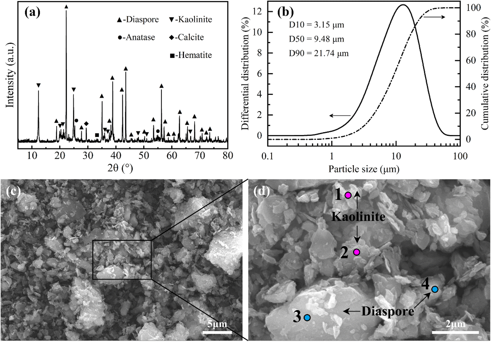 | ||
| Fig. 2 Characterizations of the high-silica bauxite: (a) XRD pattern; (b) particle size distribution; (c and d) SEM images. | ||
| Element | O | Al | Si | Ca | Ti | Fe |
|---|---|---|---|---|---|---|
| Spot 1 | 54.27 | 25.20 | 17.86 | — | 1.56 | 1.11 |
| Spot 2 | 51.06 | 27.13 | 19.55 | — | 0.71 | 1.55 |
| Spot 3 | 53.36 | 41.46 | 3.38 | — | 0.66 | 1.24 |
| Spot 4 | 46.03 | 43.19 | 4.86 | 3.37 | 1.22 | 1.33 |
| Average | 51.18 | 34.25 | 11.41 | 0.84 | 1.04 | 1.31 |
All the chemical reagents used in the study are analytically pure. The concentration of concentrated sulfuric acid is 18 mol L−1, which was diluted with distilled water to the specified concentration.
2.2 Methods and processes
The high-silica bauxite was mixed evenly with various amounts of Na2CO3 in a ceramic mortar. The mixtures were transferred to a muffle furnace and sintered for a certain time after the temperature is raised to a specified level. The sintered samples were cooled to room temperature and then ground to below 74 μm in particle size for leaching. The experimental ranges of Na2CO3 dosage, sintering temperature and sintering time were determined by phase diagram calculation, simultaneous thermal analysis and previous experience, respectively.The sintered samples were leached in distilled water at 75 °C for 15 min with a solid/liquid ratio of 1 g/15 mL. Water leaching residues were separated from the slurries, washed five times with hot distilled water, and then dried at 105 °C for 2 h. The dry residues were leached in a 2 mol L−1 sulfuric acid solution at room temperature for 10 min with a solid/liquid ratio of 1 g/10 mL. After acid leaching, no solid–liquid separation was performed. The acid leaching solutions were aged at 85 °C for 1.5 h to precipitate silica gel, which was subsequently separated and washed with hot distilled water until neutral. The silica gels were dried at 110 °C for 12 h to obtained silica powders.
The contents of Al2O3 and SiO2 in solid samples were analyzed by complexometric titration and spectrophotometry (or hydrofluoric acid gravimetry), respectively. The recovery efficiencies of Al2O3 and SiO2 were calculated according to the following equations.
| ηA1 = [1 − (cA2/cS2)/(cA1/cS1)] × 100% | (1) |
| ηA2 = (m2 × cA2 − m3 × cA3)/(m1 × cA1) × 100% | (2) |
| ηAT = ηA1 + ηA2 | (3) |
| ηS = m3 × cS3/(m1 × cS1) × 100% | (4) |
2.3 Characterizations of solid samples
Particle size distribution was analyzed by a Bettersize 2000 laser particle size analyzer. Chemical compositions were determined by a Shimadzu 1800 X-ray fluorescence (XRF) spectrometer. X-ray diffraction (XRD) patterns were recorded on a Rigaku D/MAX 2000 X-ray diffractometer and the mineral compositions were identified using the Jade software. Thermo-gravimetric analysis (TGA) and differential scanning calorimetric (DSC) were performed using a Mettler Toledo 1/1600 simultaneous thermal analyzer at a heating rate of 10 °C min−1 in a nitrogen atmosphere. The micromorphology and element distribution were conducted by a scanning electron microscopy equipped with energy disperse X-ray spectrometry (MLA650F, F.E.I.). Specific surface area was analyzed by a Brunauer–Emmett–Teller (BET) surface area analyzer (Nova Station A, Quantachrome).3 Results and discussion
3.1 Setting of experimental parameters
In the sintering process, Na2CO3 dosage, sintering temperature and sintering time are the key parameters affecting the extraction of Al2O3 and SiO2. A theoretical analysis must be performed to rationalize the experimental range of these parameters.The dosages of sintering additives are usually determined by the contents of the major components in bauxite. In the traditional lime-soda sintering process, the dosages of Na2CO3 and CaO are controlled by the molar ratios of Na2O/Al2O3 ≈ 1 and CaO/SiO2 ≈ 2 to ensure the formations of NaAlO2 and Ca2SiO4, respectively.16,38 In this study, both Al2O3 and SiO2 would react with Na2CO3 due to the absence of CaO. Therefore, the molar ratio of Na2O/(Al2O3 + SiO2) (N/(A + S)) should be used as the indicator for controlling Na2CO3 dosage.
Phase diagram calculations are generally used to model the equilibrium behavior of multi-component systems at various compositions and temperatures.39 The experimental range of N/(A + S) could be determined by analyzing the equilibrium phase changes in the Na2O–Al2O3–SiO2 system. The phase diagram of the Na2O–Al2O3–SiO2 system was calculated using the phase diagram module of FactSage software based on the FACT oxide compounds and solutions (FToxid) databases, as shown in Fig. 3. When the mole fraction of Na2O is less than 0.41, Al2O3, SiO2 or NaAl9O14 appear as stable phases, indicating that Na2O is insufficient to fully react with Al2O3 and SiO2. When the mole fraction of Na2O is above 0.57, Na2O is present as one of the stable phases, indicating its excess in the system. As the mole fraction of Na2O is in the range of 0.41–0.57, the stable phases are NaAlO2 solid solution coupled with Na2SiO3, Na4SiO4 or a liquid slag. Among them, NaAlO2 solid solution is the effective phase for alumina extraction. Therefore, it is more appropriate for the mole fraction of Na2O between 0.41–0.57, which is converted to N/(A + S) of 0.69–1.33. Considering that minor amounts of Fe2O3, TiO2 and other components in bauxite would have a certain influence on Na2CO3 dosage, the experimental range of N/(A + S) was extended to 0.6–1.4 in this study.
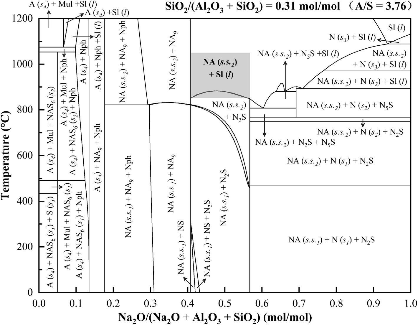 | ||
| Fig. 3 Calculated phase diagram of the Na2O–Al2O3–SiO2 system (A – Al2O3, N – Na2O, S – SiO2, NA – NaAlO2, NA9 – NaAl9O14, NS – Na2SiO3, N2S – Na4SiO4, N5S – Na10SiO7, NAS6 – NaAlSi3O8, Mul – mullite, Nph – nepheline, Sl – slag, s – solid, l – liquid, s.s. – solid solution). | ||
In order to determine the experimental range of sintering temperature, the thermal behavior of the mixture of bauxite and Na2CO3 with N/(A + S) = 1 during heating was analyzed by TGA/DSC under a nitrogen atmosphere, as shown in Fig. 4(a). There were three endothermic peaks at 89 °C, 508 °C and 849 °C, and one exothermic peak at 1068 °C on the DSC curve. The endothermic peaks at 89 °C and 508 °C were primarily attributed to the removal of adsorbed water and structural water, respectively. Accordingly, significant weight losses were observed around 89 °C and 508 °C on the TG curves. After removing the structural water, diaspore (α-Al2O3·H2O) and kaolinite (Al2O3·2SiO2·2H2O) were transformed into alpha-alumina (α-Al2O3) and metakaolinite (Al2O3·2SiO2), respectively, which can further react with Na2CO3 to form NaAlO2 solid solutions (Na2−xAl2−xSixO4, x ≤ 0.55) eventually.37 Therefore, the weight loss in the TG curve above 600 °C was primarily attributed to the release of CO2 from the reaction between bauxite and Na2CO3. The third endothermic peak was located at about 849 °C, where the melting of Na2CO3 significantly increased the reaction rate between bauxite and Na2CO3,40 resulting in a significant increase in the weight loss rate of the TG curve. Thus, the sintering temperature should be set above 849 °C to improve the sintering efficiency and shorten the sintering time. The TG curve was no longer significantly losing weight upon reaching a temperature of about 1050 °C, indicating that Na2CO3 was fully involved in the reaction with bauxite. Therefore, the experimental upper limit of the sintering temperature could be set at 1050 °C. In summary, the range of sintering temperature investigated in this study was set as 850–1050 °C. According to Fig. 3, the stable phases at 850–1050 °C were primarily NaAlO2 solid solution and a liquid slag. The exothermic peak at 1068 °C indicated that some exothermic reactions occurred in the temperature range of 1000–1100 °C. In addition, the TGA/DSC results under nitrogen atmosphere are highly similar to those under air atmosphere (Fig. 4(b)) that we studied previously,37 indicating that different atmospheres and variable oxygen exposure have no obvious impact on the sintering process.
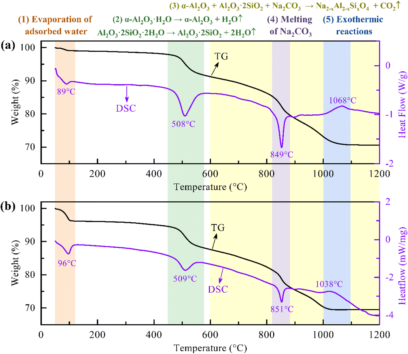 | ||
| Fig. 4 TG and DSC curves of the mixture of bauxite and Na2CO3 with N/(A + S) = 1 under nitrogen (a) and air (b)37 atmospheres. | ||
The sintering time depends on the reaction rate, which in turn depends on the sintering temperature. In our previous studies, the sintering time was usually set to 30 min.36,37 In this study, the experimental range of sintering time was set to 10–50 min.
3.2 Effects of sintering parameters on the extraction of alumina and silica
The effects of sintering temperature, sintering time, and N/(A + S) on the extraction of Al2O3 and SiO2 were investigated sequentially according to the set experimental ranges, and the results were shown in Fig. 5 and 6. | ||
| Fig. 5 Effects of sintering temperature (a), sintering time (b), and N/(A + S) (c) on the recovery efficiencies of Al2O3. | ||
 | ||
| Fig. 6 Effects of sintering temperature (a), sintering time (b), and N/(A + S) (c) on the recovery efficiency of SiO2 and the purity of silica powder. | ||
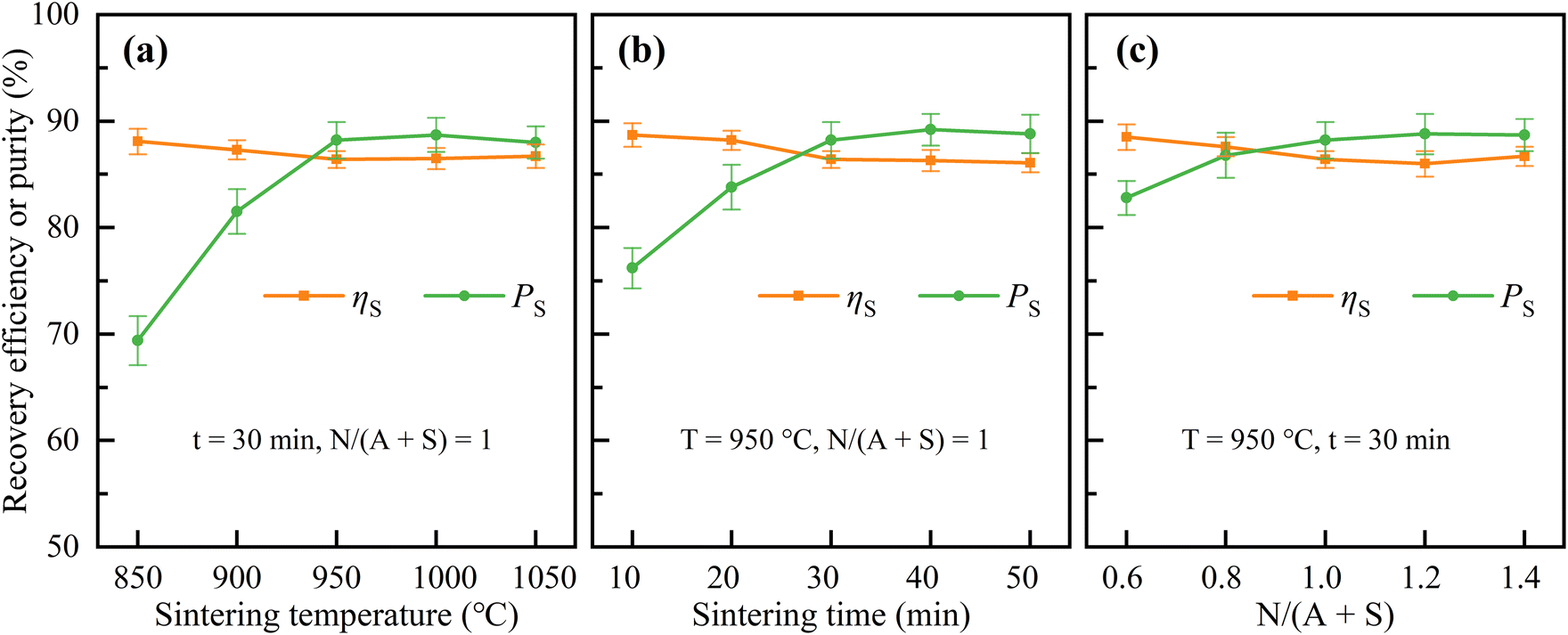
As shown in Fig. 5, the sintering parameters have a significant impact on the recovery efficiencies of Al2O3. Under the conditions of N/(A + S) = 1 and a sintering time of 30 min, the recovery efficiency of Al2O3 in water leaching process (ηA1) was first increased and then decreased when the sintering temperature was increased from 850 °C to 1050 °C and reached a maximum value of 84.2% at 950 °C. Under the conditions of N/(A + S) = 1 and a sintering temperature of 950 °C, ηA1 increased significantly when the sintering time was prolonged from 10 min to 30 min. Upon further prolonging the sintering time to 50 min, ηA1 was stabilized at about 84%. Under the conditions of a sintering temperature of 950 °C and a sintering time of 30 min, ηA1 continued to increase from 37.3% to 87.1% when N/(A + S) was increased from 0.6 to 1.4, and the increase became gradually lower. The recovery efficiency of Al2O3 in acid leaching process (ηA2) showed an opposite trend to that of ηA1, while the total recovery efficiency of Al2O3 (ηAT) showed a similar trend to that of ηA1 with lower rangeability. ηAT was maintained above 90%, up to 98.3%.
As shown in Fig. 6, the sintering parameters had little effect on the recovery efficiency of SiO2 (ηS), but had a significant effect on the purity of silica powder (PS). ηS was mainly distributed in the range of 85–89% with slight variations. Silica powder had a high purity of 87–90% under the conditions of sintering temperature of 950–1050 °C, sintering time of 30–50 min or N/(A + S) = 1–1.4. But under other conditions, the purity of silica powder was lower.
According to the above experimental results, the optimal sintering parameters were selected as sintering temperature of 950 °C, sintering time of 30 min and N/(A + S) = 1. Under these conditions, ηA1, ηA2, ηAT, and ηS were 84.2%, 13.5%, 97.7% and 86.4%, respectively. The silica powder obtained at optimal sintering parameters had a purity of 88.2%. The chemical compositions of the corresponding solid samples are shown in Table 3.
| Component | Al2O3 | SiO2 | Fe2O3 | CaO | Na2O | TiO2 | LOI |
|---|---|---|---|---|---|---|---|
| Sintered sample | 42.3 ± 1.0 | 11.4 ± 0.4 | 2.7 ± 0.2 | 0.6 ± 0.1 | 39.2 ± 0.8 | 1.6 ± 0.1 | 1.7 ± 0.3 |
| Water leaching residue | 20.0 ± 0.6 | 34.4 ± 0.9 | 9.5 ± 0.3 | 2.3 ± 0.1 | 9.2 ± 0.5 | 5.5 ± 0.3 | 16.2 ± 1.9 |
| Silica powder | 1.1 ± 0.2 | 88.2 ± 1.7 | 0.6 ± 0.2 | 0.5 ± 0.1 | 0.6 ± 0.1 | 2.6 ± 0.3 | 6.5 ± 1.5 |
3.3 Phase transformations
The phase transformations in the sintered samples and water leaching residues obtained at various sintering parameters were analyzed by XRD, and the results are shown in Fig. 7.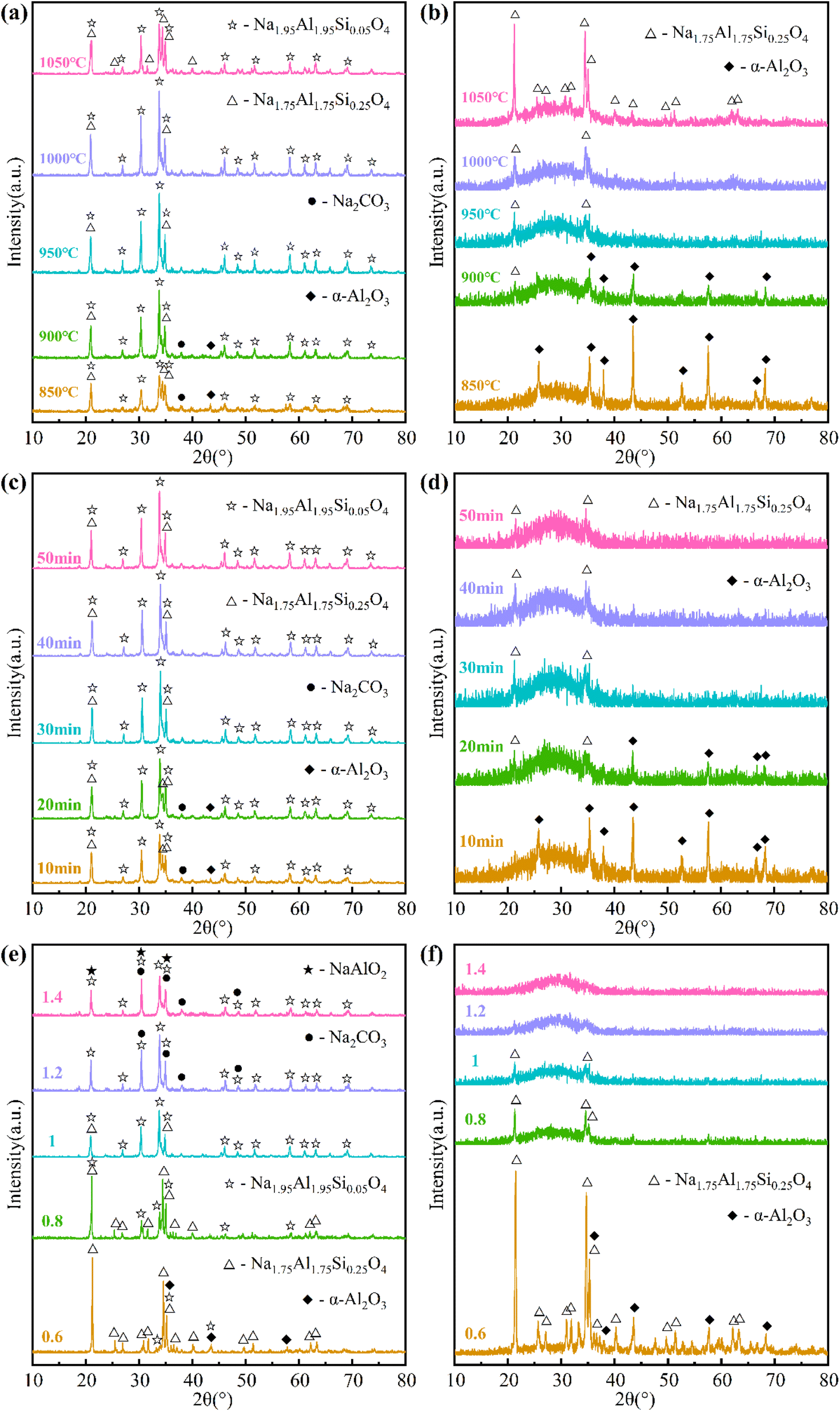 | ||
| Fig. 7 XRD patterns of sintered samples (a, c and e) and water leaching residues (b, d and f). | ||
Fig. 7(a) shows the XRD patterns of the sintered samples obtained at different sintering temperatures. At 850 °C, the crystallographic phases in the sintered sample were primarily Na1.95Al1.95Si0.05O4 and Na1.75Al1.75Si0.25O4. In addition, trace amounts of α-Al2O3 and Na2CO3 were also present in the sintered sample, indicating that the reaction between bauxite and Na2CO3 had not yet fully occurred. As the sintering temperature increased to 950 °C, the diffraction peaks of Na1.75Al1.75Si0.25O4, α-Al2O3 and Na2CO3 weakened, while those of Na1.95Al1.95Si0.05O4 increased in intensity, indicating that Na1.75Al1.75Si0.25O4, α-Al2O3 and Na2CO3 reacted to form Na1.95Al1.95Si0.05O4. At 950 °C and above, only Na1.95Al1.95Si0.05O4 and Na1.75Al1.75Si0.25O4 were detected in the sintered samples, and the former was gradually converted into the latter with increasing temperature. According to the TGA/DSC analysis (Fig. 4), the transformation of Na1.95Al1.95Si0.05O4 into Na1.75Al1.75Si0.25O4 was exothermic. Fig. 7(b) shows the XRD patterns of the water leaching residues corresponding to the sintered samples in Fig. 7(a). At 850 °C, only α-Al2O3 was detected in the water leaching residue. As the sintering temperature increased to 1050 °C, the diffraction peaks of α-Al2O3 weakened and disappeared, while those of Na1.75Al1.75Si0.25O4 arose and increased in intensity. At 950 °C and above, only Na1.75Al1.75Si0.25O4 were detected in the water leaching residues. In addition, an amorphous peak was present in where 2θ is in the range of 20–40°, indicating the presence of amorphous phase in the water leaching residues.
The XRD patterns of the sintered samples and water leaching residues obtained at different sintering times were shown in Fig. 7(c) and (d), respectively. The changes in the XRD patterns at 10–30 min presented similar trends to those at 850–950 °C in Fig. 7(a) and (b). When the sintering time prolonged from 30 min to 50 min, the XRD patterns had no obvious changes anymore.
The XRD patterns of the sintered samples obtained at different N/(A + S) were shown in Fig. 7(e). When N/(A + S) was 0.6, Na1.75Al1.75Si0.25O4, α-Al2O3 and Na1.95Al1.95Si0.05O4 were detected in the sintered sample, in which Na1.75Al1.75Si0.25O4 played a dominant role. As N/(A + S) increased from 0.6 to 1.4, Na1.75Al1.75Si0.25O4 and α-Al2O3 transformed into Na1.95Al1.95Si0.05O4 entirely. In addition, the diffraction peaks of Na2CO3 and NaAlO2 arose at N/(A + S) of 1.2 and 1.4, respectively. The presence of Na2CO3 in the sintered samples suggested an over-dosing of it. The XRD patterns of the water leaching residues corresponding to the sintered samples in Fig. 7(e) were shown in Fig. 7(f). When N/(A + S) was 0.6, Na1.75Al1.75Si0.25O4 and α-Al2O3 were detected in the water leaching residue. As N/(A + S) increased from 0.6 to 1.4, the diffraction peaks of Na1.75Al1.75Si0.25O4 and α-Al2O3 weakened and disappeared, leaving only those of amorphous phases.
Comparing the major phases in the sintered samples (Fig. 7(a), (c) and (e)) with those in the corresponding water leaching residues (Fig. 7(b), (d) and (f)), it can be known that Na2CO3, Na1.95Al1.95Si0.05O4 and NaAlO2 were entirely dissolved during water leaching, while Na1.75Al1.75Si0.25O4 was partially dissolved, and α-Al2O3 was not dissolved. Therefore, the extraction of Al2O3 in water leaching process was primarily related to the formation and transformation of Na2−xAl2−xSixO4 (x = 0, 0.05 and 0.25) in the sintered samples. According to Fig. 5, ηA1 was relatively low when Na1.75Al1.75Si0.25O4 was dominant in the sintered samples, and significantly increased with the transformation of Na1.75Al1.75Si0.25O4 into Na1.95Al1.95Si0.05O4. When Na1.95Al1.95Si0.05O4 was further converted into NaAlO2, ηA1 increased only slightly. In the water leaching process, few SiO2 in the sintered sample was leached out with the dissolution of Na1.75Al1.75Si0.25O4 and Na1.95Al1.95Si0.05O4, while most of SiO2 was left in the water leaching residue. After water leaching, α-Al2O3, Na1.75Al1.75Si0.25O4, and an amorphous phase were retained in the water leaching residues, where one of the latter two phases dominated. According to the experimental phenomena, the water leaching residues without α-Al2O3 was almost completely dissolved during acid leaching, indicating that Na1.75Al1.75Si0.25O4 and the amorphous phase have excellent acid solubility. As a result, almost all the remaining Al2O3 and SiO2 in the water leaching residue were extracted, leading to high levels of ηAT, ηS and the purity of silica powder. In contrast, ηAT was lower when α-Al2O3 was present in the water leaching residue, indicating that α-Al2O3 was difficult to dissolve during acid leaching. As a result, the purity of silica powder was also lower.
The optimal sintering parameters (950 °C, 30 min and N/(A + S) = 1) were selected to compare the identified phases in Fig. 7 with the thermodynamic predictions of Fig. 3. The identified phases in the sintered sample were primarily Na2−xAl2−xSixO4 (x = 0.05 and 0.25), which are NaAlO2 solid solutions predicted by thermodynamics. In addition to the NaAlO2 solid solutions, a liquid slag was also predicted by thermodynamics, which contained most of the SiO2 in the Na2O–Al2O3–SiO2 system. The crystallinity of the sintered sample was calculated to be 80.3%, indicating the presence of an amorphous phase, which is the main Si-bearing phase in the sintered sample and corresponds to the liquid slag predicted by thermodynamics.
3.4 Micromorphology
In order to further reveal the process mechanism, the micromorphology of the sintered sample and water leaching residue obtained at optimal sintering parameters were observed and analyzed.Fig. 8 shows the XRD pattern and SEM images results for the sintered sample. According to Fig. 8(b), the particles in the sintered sample could be divided into two groups. As shown in Fig. 8(c), the first kind of particles were loose and porous aggregates of fine lamellar crystals, which is favorable for water leaching. According to Fig. 8(a), the crystalline phase in the sintered sample was primarily Na2−xAl2−xSixO4 (x = 0.05 and 0.25). Combined with the EDS results of spot 5–7 (Table 4), it could be concluded that the first kind of particles mostly consisted of Na2−xAl2−xSixO4 (x = 0.05 and 0.25). As shown in Fig. 8(d), the second kind of particles were in the form of dense blocks with smooth surfaces and numerous microscopic pores inside. The micromorphology indicated that the second kind of particles were amorphous, which verifies the presence of an amorphous phase in the sintered sample. According to Table 4, the second kind of particles (spot 8–10) contained less Na, Al and more Ca, Ti, Fe compared to the first kind of particles (spot 5–7). The average A/S of these two kinds of particles were 4.23 and 2.61, respectively, while that of the sintered sample was 3.71. Based on the difference in A/S, the proportion of the first and second kinds of particles was calculated to be about 68% and 32%, respectively.
 | ||
| Fig. 8 XRD pattern (a) and SEM images (b–d) of the sintered sample obtained at optimal sintering parameters. | ||
| Element | O | Na | Al | Si | Ca | Ti | Fe |
|---|---|---|---|---|---|---|---|
| Spot 5 | 33.82 | 31.52 | 27.02 | 5.68 | 0 | 0.64 | 1.32 |
| Spot 6 | 22.81 | 32.3 | 31.2 | 6.42 | 0 | 3.53 | 3.74 |
| Spot 7 | 32.39 | 36.3 | 18.09 | 3.82 | 0.38 | 0.48 | 1.21 |
| Average (5–7) | 29.67 | 33.37 | 25.44 | 5.31 | 0.13 | 1.55 | 2.09 |
| Standard deviation | 5.99 | 2.56 | 6.70 | 1.34 | 0.22 | 1.72 | 1.43 |
| Spot 8 | 33.83 | 26.88 | 16.52 | 5.32 | 0.36 | 1.31 | 3.71 |
| Spot 9 | 34.11 | 29.02 | 14.93 | 4.94 | 0.78 | 1.63 | 3.44 |
| Spot 10 | 33.36 | 32.71 | 15.04 | 5.45 | 1 | 3.99 | 8.45 |
| Average (8–10) | 33.77 | 29.54 | 15.50 | 5.24 | 0.71 | 2.31 | 5.20 |
| Standard deviation | 0.38 | 2.95 | 0.89 | 0.27 | 0.33 | 1.46 | 2.82 |
Fig. 9 shows the XRD pattern and SEM images of the water leaching residue obtained at optimal sintering parameters. According to Fig. 9(a), the water leaching residue was primarily composed of amorphous phases. As shown in Fig. 9(b)–(d), the amorphous particles were primarily massive, with rough surfaces and numerous dissolution pores, which was inferred to be the result of partial dissolution and secondary reactions of the amorphous phase particles in the sintered sample during water leaching. The EDS results of the amorphous particles in the sintered sample (Table 4) and water leaching residue (Table 5) show that the contents of Na and Al decreased after water leaching, while those of Si, Ca, Ti and Fe increased relatively, further confirming the above inference. As a result, the A/S of the amorphous particles decreased to 0.56, which was similar to that of the water leaching residue (0.58). In addition, the particles in the water leaching residue have a size of less than 100 μm and a porous structure, which favors acid leaching.
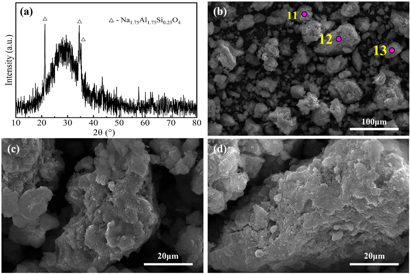 | ||
| Fig. 9 XRD pattern (a) and SEM images (b–d) of the water leaching residue obtained at optimal sintering parameters. | ||
| Element | O | Na | Al | Si | Ca | Ti | Fe |
|---|---|---|---|---|---|---|---|
| Spot 11 | 44.16 | 9.37 | 11.06 | 18.09 | 2.16 | 3 | 5.87 |
| Spot 12 | 40.75 | 10.52 | 12.34 | 19.06 | 2.2 | 3.99 | 11.14 |
| Spot 13 | 41.64 | 8.75 | 11.06 | 16.9 | 2.55 | 2.89 | 6.95 |
| Average (11–13) | 42.18 | 9.55 | 11.49 | 18.02 | 2.30 | 3.29 | 7.99 |
| Standard deviation | 1.77 | 0.90 | 0.74 | 1.08 | 0.21 | 0.61 | 2.78 |
3.5 Discussion of the mechanism and advantages of the novel process
Based on the above analysis results, the phase transformations of the Al- and Si-bearing minerals during sintering and leaching were revealed. In addition, the formation mechanism and application of silica gel were discussed.In this study, diaspore and kaolinite are the main Al- and Si-bearing minerals in the high-silica bauxite, respectively. In the sintering process, diaspore and kaolinite were primarily converted into Na2−xAl2−xSixO4 (x = 0, 0.05 and 0.25) and an amorphous phase by fully reacting with sufficient Na2CO3. In the water leaching process, Na2−xAl2−xSixO4 (x = 0, 0.05 and 0.25) dissolves completely or partially depending on the x value, while the amorphous phase partially dissolves and undergoes some secondary reactions. The residual amorphous phase and Na2−xAl2−xSixO4 (x = 0.25) formed the main body of the water leaching residue and were almost completely dissolved in the subsequent acid leaching process. If the dosage of Na2CO3 is insufficient or the sintering reaction does not fully occur, a part of diaspore would be dehydroxylated to form α-Al2O3, which is insoluble in both the water leaching and acid leaching processes. Fig. 10 shows the proposed mechanism at optimal sintering parameters.
 | ||
| Fig. 10 Schematic diagram of the process mechanism at optimal sintering parameters. | ||
According to Table 3, the chemical composition of the water leaching residue was dominated by SiO2, Al2O3 and Fe2O3, which underwent the following reactions during acid leaching.41,42
| M2SiO4(s) + 2H2SO4(aq) → H4SiO4(aq) + 2MSO4(aq) | (5) |
| Al2O3(s) + 3H2SO4(aq) → Al2(SO4)3(aq) + 3H2O | (6) |
| Fe2O3(s) + H2SO4(aq) → Fe2(SO4)3(aq) + 3H2O | (7) |
Accordingly, the compositions of the acid leaching solution were dominated by H4SiO4, Al2(SO4)3, and Fe2(SO4)3. H4SiO4 will gradually polymerize in the acid leachate, forming dimers, trimers, cyclic oligomers and up to silica gels,43,44 as shown in Fig. 11. Pure silica gel was obtained using the method described in Section 2.2, as shown in Fig. 12(a). The silica gel has excellent water absorbing properties, containing 90–95% water, which can be processed as a water retention agent, desiccant, or absorbent. The silica powder (Fig. 12(b)) obtained by drying silica gel has a high purity of 87–90%, which is primarily amorphous according to Fig. 12(c). As shown in Fig. 12(d) and (e), the amorphous silica particles are primarily layered and thus have a specific surface area of up to ∼406 m2 g−1. Therefore, the silica gel can also be used as a raw material for the production of silica-based products. After separating out silica gel, the remaining solution had Al2(SO4)3 and Fe2(SO4)3 as the main components, which can be used to produce PAFS.35
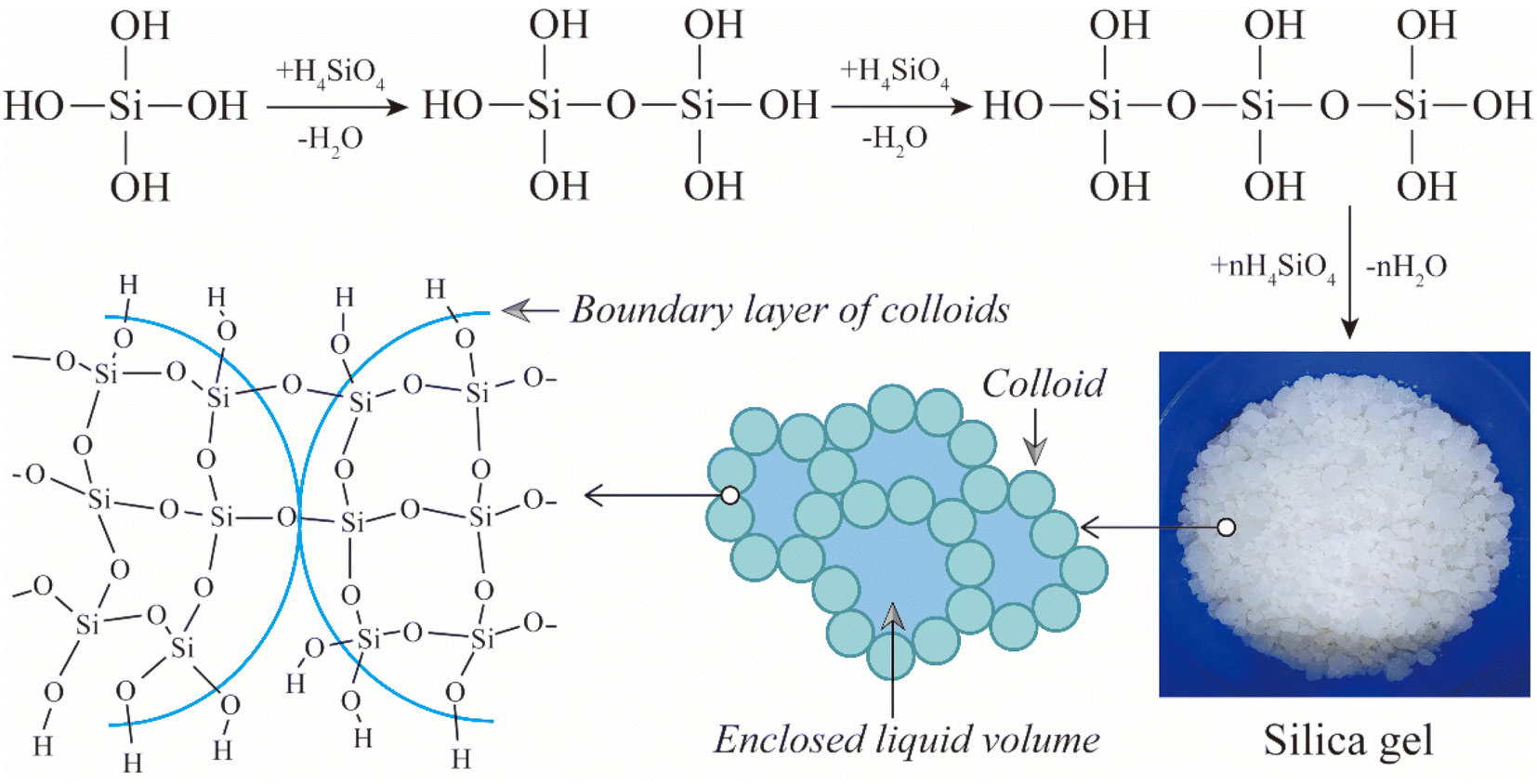 | ||
| Fig. 11 Diagram of the formation mechanism of silica gel.43 | ||
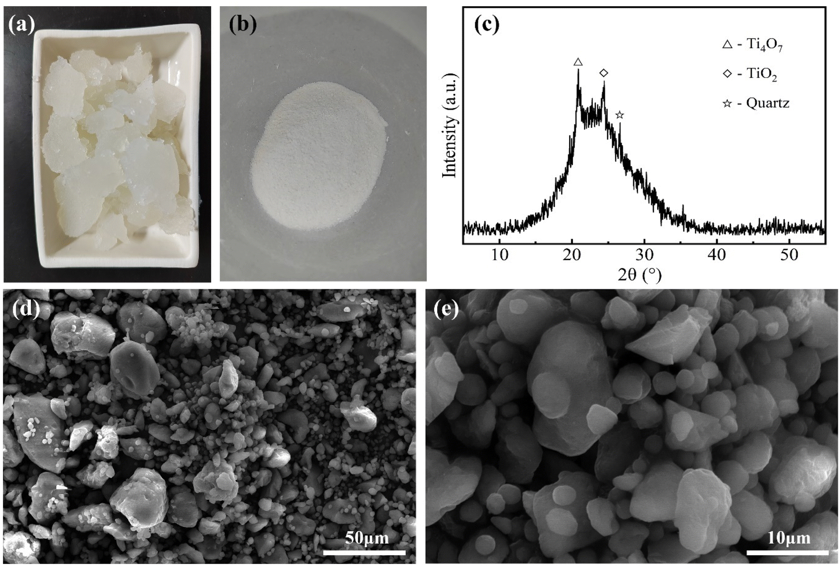 | ||
| Fig. 12 Photographs of silica gel (a) and silica powder (b); XRD pattern (c) and SEM images (d and e) of silica powder. | ||
The above process realizes the comprehensive utilization of high silica bauxite and has obvious advantages compared with the traditional lime-soda sintering process, as shown in Table 6. First, lime is not introduced into the sintering process, reducing the material flow and improving the production efficiency. Second, the sintering temperature is reduced from 1250–1350 °C to 950 °C, resulting in lower sintering energy consumption. Third, SiO2 and Fe2O3 are also extracted and utilized with high levels of recovery in addition to Al2O3. Fourth, residue is fully utilized without discharge.
| Process | Sintering parameters | Recovery efficiency | Emission of residue | ||
|---|---|---|---|---|---|
| Al2O3 | SiO2 | Fe2O3 | |||
| The lime-soda sintering process | 1250–1350 °C | 88–92% | — | — | >1.5 t per t-Al2O3 |
| C/S = 2, N/A = 1 | |||||
| The novel process | 950 °C | 97.7% (84.2% for alumina, 13.5% for PAFS) | 86.4% | 95.9% | 0 |
| N/(A + S) = 1 | |||||
4 Conclusions
The extraction of Al2O3 and SiO2 from high-silica bauxite was realized by sintering with N2CO3 followed by two-step leaching with water and acid. During the sintering of bauxite with N2CO3, diaspore and kaolinite were transformed into α-Al2O3, Na2−xAl2−xSixO4 (x = 0, 0.05 and 0.25) and an amorphous phase. In the subsequent two-step leaching processes, α-Al2O3 was insoluble, while the other two phases were almost completely dissolved. The formation of α-Al2O3 could be avoided by adjusting sintering parameters. The optimal sintering parameters were determined experimentally to be sintering temperature of 950 °C, sintering time of 30 min, and N/(A + S) of 1. Under these conditions, ∼97% of Al2O3 and ∼86% of SiO2 were extracted for the production of alumina, PAFS and silica gel. The purity of silica gel was positively correlated with the total recovery efficiency of Al2O3. The dried silica gel reached a purity of ∼88% at optimal sintering parameters. These findings suggest an idea for the comprehensive utilization of high-silica bauxite and the minimization of residue.Conflicts of interest
There are no conflicts to declare.Acknowledgements
The authors are grateful for the financial support from the Collaborative Innovation Center Project of the Shaanxi Provincial Department of Education, China (No. 21JY027).References
- N. Zhang, A. V. Nguyen and C. Zhou, Adv. Colloid Interface Sci., 2018, 254, 56–75 CrossRef CAS PubMed.
- P. Smith, Hydrometallurgy, 2009, 98, 162–176 CrossRef CAS.
- Z. Wu, H. Lv, M. Xie, L. Li, H. Zhao and F. Liu, Ceram. Int., 2022, 48, 18676–18686 CrossRef CAS.
- X. Pan, H. Wu, H. Yu and S. Bi, Hydrometallurgy, 2020, 197, 105469 CrossRef CAS.
- N. Kawashima, L. Shi, N. Xu, J. Li and A. R. Gerson, Hydrometallurgy, 2016, 159, 75–86 CrossRef CAS.
- B. Gibson, D. G. Wonyen and S. C. Chelgani, Miner. Eng., 2017, 114, 64–73 CrossRef CAS.
- Y. Wu, X. L. Pan, Y. J. Han and H. Y. Yu, Trans. Nonferrous Met. Soc. China, 2019, 29, 2627–2637 CrossRef CAS.
- Y. Xu, J. Li, C. Chen, Y. Lan and L. Wang, JOM, 2020, 72, 2705–2712 CrossRef CAS.
- X. B. Li, H. Y. Wang, Q. S. Zhou, T. G. Qi, G. H. Liu, Z. H. Peng and Y. L. Wang, Trans. Nonferrous Met. Soc. China, 2019, 29, 416–423 CrossRef CAS.
- Q. Wang, X. F. Sheng, L. Y. He and Y. Shan, Miner. Eng., 2018, 128, 179–186 CrossRef CAS.
- G. Lü, T. Zhang, X. Zhu, C. Zheng, Y. Wang, W. Zhang and Z. Zhang, Chin. J. Chem. Eng., 2019, 27, 1965–1972 CrossRef.
- Y. Wang, T. Zhang, G. Lyu, L. Ma and W. Zhang, J. Cleaner Prod., 2021, 290, 125828 CrossRef CAS.
- C. Liu, S. Ma, S. Zheng, Y. Luo, J. Ding, X. Wang and Y. Zhang, Hydrometallurgy, 2018, 175, 224–231 CrossRef CAS.
- S. N. Wang, S. L. Zheng and Y. Zhang, Chin. J. Process Eng., 2007, 7, 967–972 CAS.
- A. Alp and A. O. Aydin, Can. Metall. Q., 2002, 41, 41–46 CrossRef CAS.
- J. Pei, X. Pan, Y. Zhang, H. Yu and G. Tu, J. Environ. Chem. Eng., 2021, 9, 106754 CrossRef CAS.
- T. Le, S. Ju, L. Lu, J. Peng, L. Zhou and S. Wang, Hydrometallurgy, 2017, 169, 124–134 CrossRef CAS.
- A. B. ElDeeb, V. N. Brichkin, M. Bertau, Y. A. Savinova and R. V. Kurtenkov, Appl. Clay Sci., 2020, 196, 105771 CrossRef CAS.
- Y. J. Xu, H. X. Xin, H. M. Duan, Y. D. Li, Y. Wu, J. Lin and Y. C. Zhai, J. Cent. South Univ., 2022, 29, 22–31 CrossRef CAS.
- D. Tian, X. Y. Shen, Y. C. Zhai, P. Xiao and P. Webley, J. Iron Steel Res. Int., 2019, 26, 578–584 CrossRef CAS.
- D. Valeev, A. Shoppert, D. Dogadkin, T. Romashova, T. Kuz'mina and C. Salazar-Concha, Hydrometallurgy, 2023, 215, 105994 CrossRef CAS.
- Y. Zhang, J. Zhang, L. Wu, L. Tan, F. Xie and J. Cheng, J. Hazard. Mater., 2021, 404, 124044 CrossRef CAS PubMed.
- Y. Zhao, Y. Zheng, H. He, Z. Sun and A. Li, J. Environ. Chem. Eng., 2021, 9, 104770 CrossRef CAS.
- T. S. Barry, T. Uysal, M. Birinci and M. Erdemoğlu, Min., Metall., Explor., 2019, 36, 557–569 Search PubMed.
- S. Ma, Z. Wen, J. Chen and S. Zheng, Miner. Eng., 2009, 22, 793–798 CrossRef CAS.
- J. Y. Ma, Z. B. Li and Q. G. Xiao, AIChE J., 2012, 58, 2180–2191 CrossRef CAS.
- W. Liu, J. Yang and B. Xiao, Int. J. Miner. Process., 2009, 93, 220–231 CrossRef CAS.
- Y. Li, X. Pan, Z. Lv, H. Wu and H. Yu, Miner. Eng., 2022, 187, 107805 CrossRef CAS.
- Y. Xu, C. Chen, Y. Lan, L. Wang and J. Li, J. Mater. Res. Technol., 2020, 9, 7418–7426 CrossRef CAS.
- Y. Wang, T. Zhang, Y. Zhang, G. Lyu and W. Zhang, Miner. Eng., 2019, 138, 139–147 CrossRef CAS.
- G. Power, M. Grafe and C. Klauber, Hydrometallurgy, 2011, 108, 33–45 CrossRef CAS.
- X. Liu, Y. Han, F. He, P. Gao and S. Yuan, J. Hazard. Mater., 2021, 420, 126542 CrossRef CAS PubMed.
- P. S. Reddy, N. G. Reddy, V. Z. Serjun, B. Mohanty, S. K. Das, K. R. Reddy and B. H. Rao, Waste Biomass Valorization, 2021, 12, 1185–1217 CrossRef CAS.
- Y. Wang, T.-a. Zhang, G. Lyu, F. Guo, W. Zhang and Y. Zhang, J. Cleaner Prod., 2018, 188, 456–465 CrossRef CAS.
- J. Chang, A. Pan, Y. Ma, Y. Sun and S. Hu, Minerals, 2023, 13, 105 CrossRef CAS.
- J. Chang, A. Pan, Y. Ma, Y. Sun, S. Hu and K. Li, Metall. Res. Technol., 2022, 119, 114 CrossRef CAS.
- Y. Sun, A. Pan, Y. Ma, J. Chang, K. Li and S. Hu, Miner. Eng., 2022, 187, 107782 CrossRef CAS.
- T. Le, S. H. Ju, A. V. Ravindra, X. T. Li and Q. Wang, JOM, 2019, 71, 831–837 CrossRef CAS.
- C. Dessemond, G. Soucy, J.-P. Harvey and P. Ouzilleau, Minerals, 2020, 10, 519 CrossRef CAS.
- A. Kosminski, D. P. Ross and J. B. Agnew, Fuel Process. Technol., 2006, 87, 1051–1062 CrossRef CAS.
- G. Hu, H. Tang, D. He, W. Sun and L. Wang, Miner. Eng., 2021, 173, 107180 CrossRef CAS.
- H. Tanvar and B. Mishra, Sustainable Mater. Technol., 2022, 33, e00466 CrossRef CAS.
- G. Alkan, B. Yagmurlu, S. Cakmakoglu, T. Hertel, Ş. Kaya, L. Gronen, S. Stopic and B. Friedrich, Sci. Rep., 2018, 8, 5676 CrossRef PubMed.
- D. Voßenkaul, A. Birich, N. Müller, N. Stoltz and B. Friedrich, J. Sustain. Metall., 2017, 3, 79–89 CrossRef.
| This journal is © The Royal Society of Chemistry 2023 |