
 Open Access Article
 This Open Access Article is licensed under a
 Creative Commons Attribution 3.0 Unported Licence
Effect of organic solvents on calcium minodronate crystal morphology in aqueous solution: an experimental and theoretical study†
Chen Zhuanga,
Muyuan Chaia,
Yuhui Zhang*b and
Xuetao Shi *acdef
aSchool of Materials Science and Engineering, South China University of Technology, Guangzhou 510640, China
bSchool of Materials Science and Engineering, Xiamen University of Technology, Xiamen 361024, China. E-mail: joanmolin@foxmail.com
cNational Engineering Research Center for Tissue Restoration and Reconstruction, South China University of Technology, Guangzhou 510006, China. E-mail: shxt@scut.edu.cn
dKey Laboratory of Biomedical Engineering of Guangdong Province, South China University of Technology, Guangzhou 510006, China
eKey Laboratory of Biomedical Materials and Engineering of the Ministry of Education, South China University of Technology, Guangzhou 510006, China
fGuangzhou Regenerative Medicine and Health Guangdong Laboratory, 510005, Guangzhou, China
First published on 18th January 2023
Abstract
The influence of nine organic solvents on the crystal morphology of calcium minodronate (Ca(Min)2) was investigated by experimental investigations and molecular simulations. Hirshfeld analysis was used to reveal the intermolecular interactions, and the modified attachment energy (AE) model was applied to constructing the Ca(Min)2–organic–water model in different organic–water solvents. The surface structure and the mass density profile were demonstrated and analyzed. The results showed that there were different adsorption conditions in different organic–water solvents. Furthermore, it was found that the (2 0 0)/(1 1 0) side ratio of Ca(Min)2 crystal had a linear relationship with the volume of organic solvent and had a certain correlation with some solvent properties. It is believed that the research developed in this work could have a promising application in prediction of Ca(Min)2 crystal morphology and could give guidance in the selection of organic solvents to control the desirable crystal morphology.
1. Introduction
Crystal morphology is the appearance of a crystalline material, which is one of the most important factors that can influence material properties, such as solubility, stability and bioavailability, as well as processing and packaging operations.1–3 Crystal morphology can be determined by various factors, including solvents,4–8 supersaturation9,10 and additives.11–14 Among them, solvents play a significant role in adjusting adsorption on certain crystal faces and should be preferentially taken into account. For example, Song et al.15 selected typical solvents based on their electronegativity to obtain different pronamide crystal shapes, and found that solvents with identified functional groups interacted with the crystal planes in different ways, which resulted in crystals with various aspect ratios. Cui et al.16 found that both the interface structure and the interaction strength for the crystal–solvent combination were important in the solvent effect on the sucralose crystal morphology, and the solvent–crystal interaction was a key factor, which was dominated by hydrogen bonds between hydrogen atoms of the crystal and oxygen atoms of the solvents. Despite all, to search for a desired crystal morphology of a material through experiments still remains expensive and time-consuming.Recently, molecular simulation has provided new understanding of crystal morphology at the molecular level through computational models. Several theoretical models have been proposed to predict crystal morphology, such as non-mechanistic models including Bravais–Friedel–Donnay–Harker (BFDH) rule17 and attachment energy (AE) model,18,19 and mechanistic models including Monte Carlo method,20,21 interfacial structure analysis model,22 spiral growth model and 2D nucleation model.9,23,24 These theoretical models consider the influence on crystal morphology from the internal crystal structure to external environment, with increasing accuracy and complexity. Among these models, the AE model has generally become the most popular simulation method in crystal morphology prediction due to its inexpensive calculation and reliable accuracy.25 By considering the interaction energy between crystal faces and solvents, the modified AE model can be applied to crystallization in solutions. Li et al.26 studied the effects of solution conditions including solvents, temperature and supersaturation on β-HMX crystal morphology through molecular dynamics by the modified AE model, and the simulation results were well consistent with experiments. Liu et al.27 used the modified AE model to investigate the DNTF crystal morphologies in the solvents H2O/AcOH and H2O/EtOH, and further found that the (0 1 1) and (0 0 1) faces were morphologically important, which was in agreement with experimental results. Zhao et al.28 successfully extended the modified AE model to the morphology prediction of FOX-7 crystal in cyclohexanone, acetonitrile, H2O/DMF and H2O/DMSO, which was verified by the experiments. The results provided that H2O/DMF and H2O/DMSO were good solvents for recrystallization. Nevertheless, there is no reports about application of modified AE model on morphology prediction of metal organic coordination polymer.
During the synthesis of metal organic coordination polymer crystals, the addition of organic solvents can accelerate the reaction rate29–31 and change the crystal morphology.32,33 Polar aprotic organic solvents can significantly accelerate the reaction process of SN2 (Bimolecular nucleophilic substitution reaction), so they are commonly seen in the synthesis of metal bisphosphonates.34–38 However, the addition of such organic solvents have inevitable effect on the crystal morphology, thus changing the crystallization, reprocessing and bioavailability.39–44 Calcium bisphosphonates (CaBPs), one kind of novel coordination polymer of calcium and bisphosphonates, have revealed great potential in bone regeneration,45,46 anticancer drug34 and delivery system.47 Minodronate (Min) is believed as one of the most effective bisphosphonates (100–1000 times higher than pamidronate in terms of inhibiting bone resorption).48,49 As one type of CaBPs, calcium minodronate (Ca(Min)2) has been rarely investigated, especially in terms of crystal morphology. At present, there have been no experiment and simulation investigations into the influence of polar aprotic organic solvents on crystallization of Ca(Min)2. In this work, Ca(Min)2 was selected to study the effect of organic solvents on the crystal morphology. Molecular dynamic simulations were employed to reveal the morphology transformation in organic–water solvents. Experiments were conducted to demonstrate the correlation between the morphology change and the volume of organic solvent. The relationship between the morphology change and the organic solvent properties were also analyzed.
2. Experimental and simulation methods
2.1 Materials
Minodronate (Min, C9H12N2O7P2, CAS: 155648-60-5, purity > 99.5%) was obtained from Chemlin Chemical Industry Co., Ltd (Nanjing, China), calcium chloride (CaCl2, CAS: 10043-52-4, purity > 99.9%) was obtained from Macklin Biochemical Co., Ltd (Shanghai, China). The organic solvents, including acetonitrile (MeCN), acetone (ace), N-methyl-2-pyrrolidinone (NMP), dimethyl sulfoxide (DMSO), formamid (MEF), N,N-dimethylformamide (DMF), N,N-dimethylacetamide (DMAC), N,N-diethylformamide (DEF) and N,N-diethylacetamide (DEAC) were analytical pure and were purchased from Macklin Biochemical Co., Ltd (Shanghai, China). Double distilled water was prepared and preserved in the laboratory and was used throughout the experiments.2.2 Ca(Min)2 crystallization in various solvents
To investigate the morphology transformation in different organic–water solvents, a series of reaction crystallization experiments were designed and conducted. Firstly, Min and CaCl2 powders were dissolved in water to prepare 1 mM and 10 mM solutions, respectively. Secondly, 1 mL Min solution was added to each of six bottles, then gradient volumes (50 μL) with 50–250 μL of organic solvent were added and mixed uniformly. Thirdly, 100 μL CaCl2 solution were added to each bottle, then the bottles were kept at 298.15 K for 12 hours to obtain the crystals. Finally, the crystals were washed by double distilled water, and dried and collected for further characterizations. The same operations were applied to all nine organic solvents.2.3 Characterizations
The crystal morphology of Ca(Min)2 was observed and captured through an inverted fluorescence microscope (TS100, Nikon, Japan) and a scanning electron microscope (Q25, FEI, USA). Powder X-ray diffraction (PXRD) was carried out on a diffractometer (X'pert PRO, PANalytical, Netherlands) using Cu-Kα radiation. The data were recorded at room temperature with the scan range being 5–90° and steps being 0.01313°.2.4 Simulations
| Rhkl ∝ |Eatt| |
And Eatt indicates the energy released when adding a growth slice onto the crystal surface, which is calculated as:
| Eatt = Elatt − Eslice |
As is known to all, most crystals are grown from solutions, thus the effect of the solvent on crystal growth plays an important role. However, the AE model does not include the adsorption of the solvent at the crystal–solvent interface, which will normally inhibit crystal growth.25 Herein, a modified AE model was proposed. It is known that there is energy consumption when removing adsorbed solvents from a crystal face, then the attachment energy decreases and the crystal morphology in solution is different from that in vacuum.
In this work, the modified attachment energy Eatt′ is computed as follows:
| Eatt′ = Eatt − Eint |
| Eint = Etot − (Ecry + Esol) |
| Rhkl′ ∝ |Eatt′| |
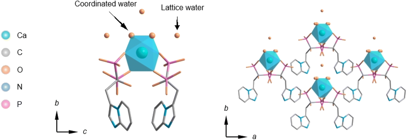 | ||
| Fig. 1 Parallel and central view of Ca(Min)2 crystal structure. | ||
Further molecular simulations were performed and completed with Materials Studio 8.0 software (Accelrys Inc., USA). The atomic charges of water molecule were appointed with q(O) = −0.72e, q(H) = 0.36e in Dreiding force field and q(O) = −1.22e, q(H) = 0.61e in Universal force field, in which case the water density by simulation is the closest to the experiment. After optimization using different forcefield/charge rules (Table S1†), Dreiding force field and Gasteiger charge calculation methods (for Ca and Min) were the most appropriate. An optimized cell with a = 19.27 Å, b = 9.74 Å, c = 17.05 Å, β = 107.99° and ρ = 1.69 g cm−3 was obtained, showing an acceptable structural deformation. The atomic charge of organic molecules were calculated by GGA/PBE functional theory and TNP basis set with electrostatic potential (ESP) fitting. The density deviation of 25 vol% organic–water solvents between experiment and simulation (1000 molecules, Dreiding force field, NPT ensemble and 500 ps) was also acceptable (<7%, Table S2†).
The construction process of the Ca(Min)2–organic–water interfacial model was displayed in Fig. S1.† First, the prediction of Ca(Min)2 crystal morphology in vacuum was conducted with the AE model and the morphological important faces were achieved. Then crystal of Ca(Min)2 was cleaved along these crystal face with a reasonable depth and construct superstructures at the U × V dimensions, ensuring that additional interaction calculations were avoided, see Table S3† for detailed constructions. A certain quantity of randomly distributed organic molecules were constructed at the experimental density (Table S4†) as the organic layer, and 500 randomly distributed water molecules were also constructed (1.0 g cm−3) as the water layer. The volume ratio of organic/water was set to 1/3, a little higher than that of the experimental method. The size of the amorphous cells was properly set as the same with the U × V of the corresponding crystal face. A vacuum layer with thickness of 100 Å was built above the solvent layer to eliminate the extra crystal–solvent interactions caused by periodic boundary conditions.
3. Results and discussion
3.1 Intermolecular interactions
The PXRD patterns were illustrated in Fig. S2† for polymorph identification. It was obvious that patterns of crystals in all nine organic–water solvents were the same with the simulated from Ca(Min)2 crystal structure and there was no polymorphic transformation, so calculations based on Ca(Min)2 crystal structure were reliable and applicable to this study. The assumption of the AE model was on the basis of the crystallography geometry and the intermolecular interactions of the crystal, so to calculate the intermolecular interactions in the Ca(Min)2 crystal was important and necessary. Basically, the connection between Ca and O atoms and Hirshfeld surface analysis50 were taken into consideration.Since AE model could not predict morphology of infinite networks, analysis of the Ca(Min)2 in terms of bonds between Ca and O atoms was necessary. As was shown in Fig. S3,† the distance between Ca and O atoms were above standard ion radius 2.21 (= 1.21 + 1.00, Table S5†), so the bonds between Ca and O were mainly ionic, thus there were no connection of Ca–O in AE model.
The intermolecular interactions were also demonstrated and calculated by Hirshfeld surface analysis. As shown in Fig. 2(a), the red spots of the surface were highlighted to represent the sites of ionic bonding and hydrogen bonding, including strong ionic bonding formation between Ca atoms and O atoms of Min and strong hydrogen bonding formation between O atoms of H2O and H atoms of Min or between H atoms of H2O and O atoms of Min. Fig. 2(b) illustrated the 2D fingerprint plot of Ca(Min)2, reflecting the characteristics of intermolecular interactions. It was seen that these interactions were mainly consist of H⋯H, H⋯O, O⋯Ca and others. Fig. 2(c) showed the relative contribution of different interactions to the Hirshfeld surface in the 2D fingerprint. It was obvious that the H⋯O contacts between H2O and Min molecules were the most frequent interactions, which comprises 51.5% area. H⋯H and O⋯Ca interactions were relatively strong in similar degrees, making up 27.4% and 3.4%, respectively. Besides, there were also other interactions (such as C⋯C) occupying 17.7% in the crystal. It was concluded that ionic bonding, hydrogen bonding and van der Waals force made most contributions, revealing that the three interactions were dominantly intermolecular contacts in the structure. Besides, detailed analysis of H⋯O interaction shows that H (inner)⋯O (outer) accounts for 20%, representing the interaction of Min as a hydrogen bond donor, and H (outer)⋯O (inner) accounts for 31.5%, representing the interaction of Min as a hydrogen bond receptor. The possible reason for the difference is the presence of crystal water and two enantiomeric Min molecules.
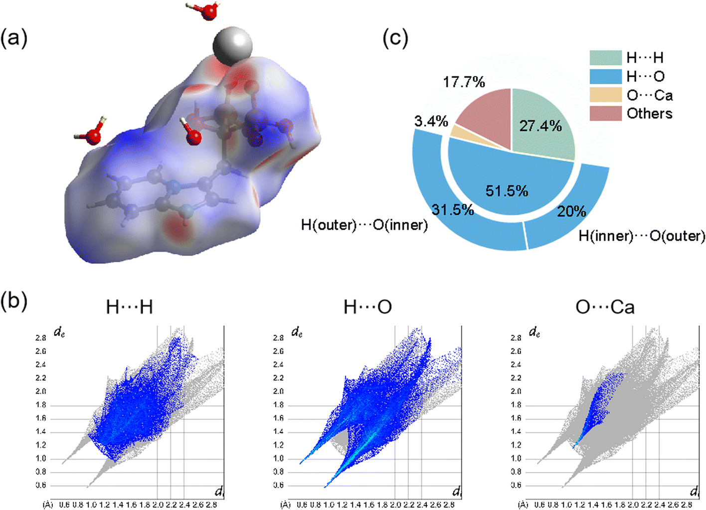 | ||
| Fig. 2 Hirshfeld surface analysis of Ca(Min)2. (a) 2D fingerprint plots; (b) 3D dnorm surface; (c) the relative contribution of different interactions to the Hirshfeld surface. | ||
3.2 Ca(Min)2 crystal morphology in vacuum
The predicted crystal morphology of Ca(Min)2 in vacuum by the AE model was demonstrated in Fig. 3. Five morphologically important crystal faces named (2 0 0), (1 1 0), (0 0 2), (1 1![[1 with combining macron]](https://www.rsc.org/images/entities/char_0031_0304.gif) ) and (2 0
) and (2 0 ![[2 with combining macron]](https://www.rsc.org/images/entities/char_0032_0304.gif) ) were illustrated in different colors. Table 1 listed the parameters of the morphology prediction computed by the AE model in vacuum. It showed that the (0 0 2) face owned the largest |Eatt| (365.24 kcal mol−1) and thus leading to the smallest facet area (4.54%), while the (2 0 ) face owned the smallest |Eatt| (185.29 kcal mol−1) and thus leading to the largest facet area (35.10%). Generally, the |Eatt| sequence of these five crystal faces was (0 0 2) > (1 1 ) > (1 1 0) > (2 0 0) > (2 0 ), however, the area of (1 1 0) was higher than (2 0 0).
) were illustrated in different colors. Table 1 listed the parameters of the morphology prediction computed by the AE model in vacuum. It showed that the (0 0 2) face owned the largest |Eatt| (365.24 kcal mol−1) and thus leading to the smallest facet area (4.54%), while the (2 0 ) face owned the smallest |Eatt| (185.29 kcal mol−1) and thus leading to the largest facet area (35.10%). Generally, the |Eatt| sequence of these five crystal faces was (0 0 2) > (1 1 ) > (1 1 0) > (2 0 0) > (2 0 ), however, the area of (1 1 0) was higher than (2 0 0).
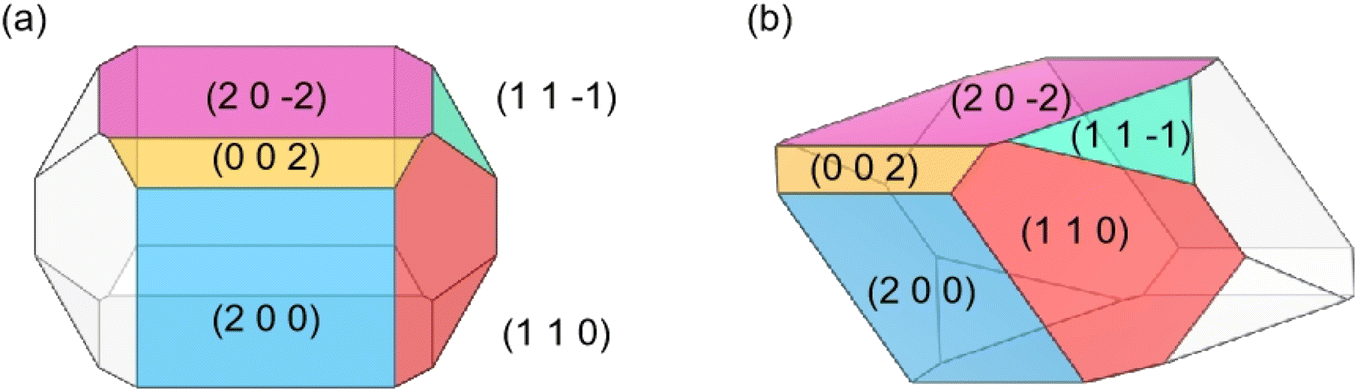 | ||
| Fig. 3 Morphology (front (a) and 45° side (b) views) of Ca(Min)2 predicted in vacuum. | ||
| (h k l) | Multiplicity | dhkl, Å | Eatt, kcal mol−1 | Rhkl | Total facet area, % |
|---|---|---|---|---|---|
| (2 0 0) | 2 | 9.16 | −250.08 | 1.00 | 20.38 |
| (1 1 0) | 4 | 8.60 | −266.26 | 0.35 | 30.96 |
| (0 0 2) | 2 | 8.11 | −365.24 | 2.96 | 4.54 |
| (1 1 ) |
4 | 8.10 | −284.40 | 0.81 | 9.03 |
| (2 0 ) |
2 | 7.29 | −185.29 | 0.61 | 35.10 |
The predicted morphology of Ca(Min)2 crystal by the AE model was enclosed by five crystal faces, being distinct from the experimental crystal morphology in organic–water solvents. Thus, it was necessary to take solvent effects on the morphology of Ca(Min)2 crystal into consideration.
To explore the contact of solvent molecules with Ca(Min)2 surface, the solvent-accessible area of different Ca(Min)2 crystal faces were demonstrated in Fig. S4.† The pink region on each crystal face represented the solvent-accessible surface. It was obvious that the (2 0 0) and (1 1 ) faces were rough with large cavities increasing the contact area, while the (1 1 0), (0 0 2) and (2 0 ) habit faces were relatively even. The parameter S was used to quantitatively evaluated the adsorption sites of solvent molecules adsorbing onto crystal faces, which could be calculated by the ratio of the solvent-accessible area (Aacc) to the crystal face area (Ahkl), as listed in Table S6.† A larger S value means a rougher surface and more possible adsorption sites. It was found that the S values of (2 0 0) and (1 1 ) faces have relatively large, indicating complex molecular arrangement of crystal surfaces. It implies that the adsorption of solvent molecules was favorable. For (1 1 0), (0 0 2) and (2 0 ) faces, the relatively low S values mean morphological smoothness, which is not conducive to the adsorption behavior of solvents. However, in consideration of surface structures and polar groups, it was found that other than the exposure of polar water molecules and protonated imidazolopyridine rings of all five surfaces, only (1 1 0) face exposed polar unsaturated Ca atoms. This revealed that all five faces was considered as polar surfaces, and (1 1 0) face implied to have the strongest capability of adsorbing polar solvents.
3.3 Ca(Min)2 crystal morphology in organic–water solvents
The solvent effects on the Ca(Min)2 morphology was investigated through molecular dynamic simulations by the modified AE model. The organic solvents selected in this study were miscible in water and could significantly accelerate crystallization. The calculation parameters of the predicted morphology were listed in Table S7.†. In each solvent system, Eint was found to be negative on all five crystal faces, suggesting that the interactions between the crystal face and the solvent layer were spontaneous. By using the (1 1 0) face as an example, different values of Eint implied that these solvents had obviously varied influences on the (1 1 0) face, due to their specific characteristic in molecular level. In terms of the total facet areas, the (0 0 2) and (1 1) faces were absent in morphology in all the solvents due to relatively higher growth rates than those of other faces. The total facet area of the (2 0 0) face in all solvents followed the sequence: DEF > ace > DMAC > DEAC > DMF > NMP > MeCN > DMSO > MEF, which revealing that the solvent effects were different on the crystal face. From the perspective of molecular structure and volume, alkylamide solvents (DMF, DMAC, DEF and DEAC) have a great influence on the crystal morphology of Ca(Min)2.
Different from the Ca(Min)2 morphology prediction with the AE model (Fig. 3), the morphology prediction with the modified AE model included only three faces, e.g. (2 0 0), (1 1 0) and (2 0 ) faces, as shown in Fig. 4 (only contained the Ca(Min)2 morphology obtained from MeCN–H2O to DEF–H2O as examples because the trend in other organic–water solvents was similar, and the experimental and predicted morphologies in other solvents were displayed in Fig. S5†). It was also obvious that the (0 0 2) and (1 1 ) faces were absent in the predicted morphologies, which was consistent with the experimental appearances. These results indicated that it was reasonable to apply the modified AE model to demonstrating the solvent effects on the Ca(Min)2 crystal morphology. Moreover, we defined (2 0 0)/(1 1 0) side ratio as the value based on optical photos (Fig. S6†) to quantitatively evaluate the influence of different organic solvents on the crystal morphology. It could be found from Fig. 5 that the side ratio is basically linear with the volume of organic solvent. When the volume of organic solvent reached 250 μL, the crystal morphology in DEF–H2O had the largest side ratio of 0.78, while the morphology in MEF–H2O had the smallest side ratio of 0.10, and the influence order of nine organic solvents is DEF > DMAC > ace > NMP > DEAC > DMF > MeCN > DMSO > MEF, which is basically consistent with the prediction results.
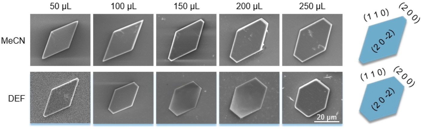 | ||
| Fig. 4 Experimental morphology of Ca(Min)2 after adding 50–250 μL organic solvents (left five SEM photos) and simulated morphology in 25 vol% organic–water solvent (right pictures, corresponding to a little higher than 250 μL in experiment). | ||
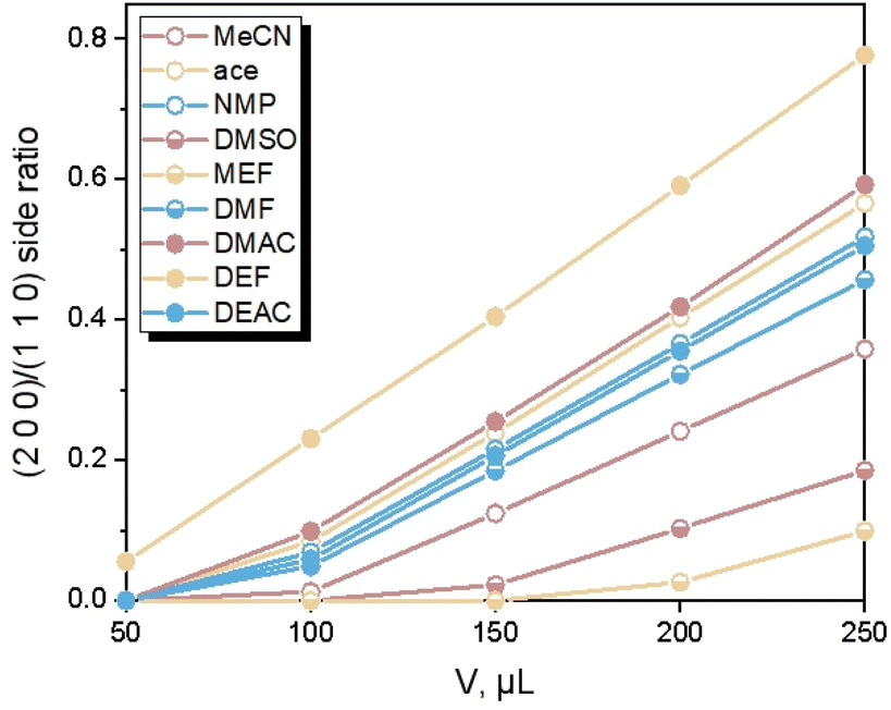 | ||
| Fig. 5 Change of (2 0 0)/(1 1 0) side ratio with volume of organic solvents. | ||
3.4 Crystal–solvent interactions on the interface
Apparently, there were relationships between Ca(Min)2 morphology and solvent properties. Solvents with different properties resulted in different adsorption behaviors onto specific crystal face, thus influence the crystal–solvent interactions. In this part, the molecular arrangement of organic–water solvents on (1 1 0) face were thoroughly studied to reveal the effect of volume of solvent molecules and some other physico-chemical properties of organic solvents were also included to reveal the relationships with side ratio.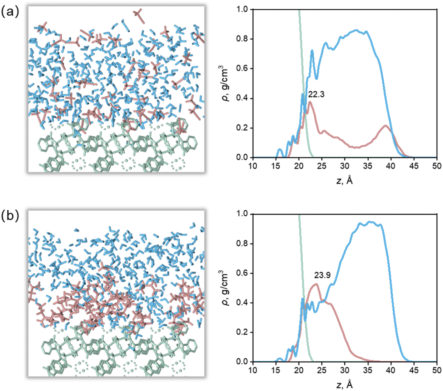 | ||
| Fig. 6 Configurations of surface–solvent interfaces (left) and mass density profile along the normal to the crystal faces (right) for the (1 1 0) face from the MD equilibrium. (a) Ca(Min)2–MeCN–H2O interfaces. (b) Ca(Min)2–DEF–H2O interfaces. Surface is in green, organic solvent is in red, and water is in blue. | ||
The highest density peaks of the water layer in the nine solvents were all above 30 Å and the density value were close to the experimental, indicating that most water molecules are sterically hindered by organic molecules, and cannot form strong short-range adsorption with the crystal surface. For MeCN, DMSO and MEF, there were some organic molecules at z ≥35 Å, where there were almost no organic molecules in other solvents, indicating that MeCN, DMSO and MEF were more susceptible to the influence of water molecules and adsorbed from the surface. It is worth noting that the beginning of the mass density profile of the water layer is lower than that of the organic layer. This is because although the organic molecules are embedded in the surface, they could not fully fill all the depressions due to their large molecular volume, so the space between the organic molecules and the surface was filled by water molecules with smaller volume.
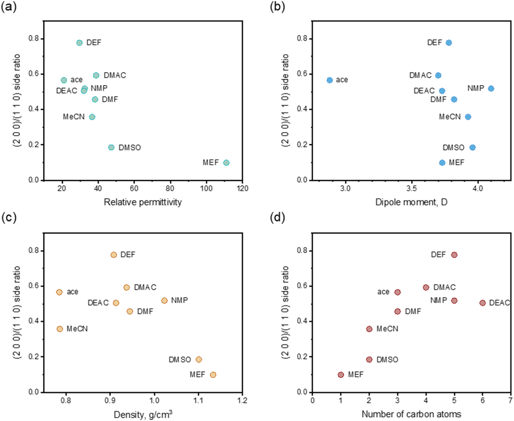 | ||
| Fig. 7 Relations between (2 0 0)/(1 1 0) side ratio and relative permittivity (a), dipole moment (b), density (c) and number of carbon atoms (d) after adding 25 vol% organic solvents. | ||
4. Conclusions
The organic solvent effect on the crystal morphology of Ca(Min)2 was systematically investigated. The predicted morphologies of Ca(Min)2 in different organic–water solvents by modified AE model were in well consistent with the corresponding experimental observations. The crystal–solvent interactions and adsorption behaviors were obtained using MD simulations and the results demonstrated that organic solvents would decrease the value of Eatt′ of all five morphological important faces and finally resulted in the disappearance of (0 0 2) and (1 1) surfaces. Furthermore, the (2 0 0)/(1 1 0) side ratios of predicted morphologies were different in solvents mainly due to different adsorption behaviors of organic and water molecules on (1 1 0) face. According to the experiment, the side ratio was linear with the volume of organic solvent and the influence order was DEF > DMAC > ace > NMP > DEAC > DMF > MeCN > DMSO > MEF. Additionally, the side ratio was approximately negatively related to the relative permittivity, dipole moment and density of organic solvent, and positively related to the number of carbon atoms in organic molecules. This work may provide an effective way of altering Ca(Min)2 crystal morphology for improvement of their reprocessing, filling property and biodegradability, and give a guidance in selection and addition of organic solvents to control the desirable crystal morphology.
Author contributions
This work was planned and proceeded by discussion among Chen Zhuang, Muyuan Chai, Yuhui Zhang and Xuetao Shi. All experiments and simulations were completed by Chen Zhuang. The analysis of experimental results was assisted by Muyuan Chai and the parametric construction of simulations was advised by Yuhui Zhang. The manuscript was revised and decided by Xuetao Shi.Conflicts of interest
There are no conflicts to declare.Acknowledgements
This work was financially supported from the National Key Research and Development Program of China (2021YFB3800800, 2018YFA0703000), the National Natural Science Foundation of China (32022041), the Key Research and Development Program of Guangzhou (202007020002), and the Science and Technology Program of Guangdong Province (2019B010941002).Notes and references
- Q. Yi, J. Chen, Y. Le, J. Wang, C. Xue and H. Zhao, J. Cryst. Growth, 2013, 372, 193–198 CrossRef CAS
.
- Z. Liang, J. F. Chen, Y. Ma, W. Wang, X. Han, C. Xue and H. Zhao, CrystEngComm, 2014, 16, 5997–6002 RSC
- C. H. Gu, V. Young Jr and D. J. W. Grant, J. Pharm. Sci., 2001, 90, 1878–1890 CrossRef CAS PubMed
- J. Li and M. F. Doherty, Cryst. Growth Des., 2017, 17, 659–670 CrossRef CAS
- I. Benmessaoud, O. Koutchoukali, M. Bouhelassa, A. Nouar and S. Veesler, J. Cryst. Growth, 2016, 451, 42–51 CrossRef CAS
- I. Hod, Y. Mastai and D. D. Medina, CrystEngComm, 2011, 13, 502–509 RSC
- M. K. Singh and A. Banerjee, Cryst. Growth Des., 2013, 13, 2413–2425 CrossRef CAS
- J. H. Urbelis and J. A. Swift, Cryst. Growth Des., 2014, 14, 1642–1649 CrossRef CAS
- H. M. Shim, H. S. Kim and K. K. Koo, Cryst. Growth Des., 2015, 15, 1833–1842 CrossRef CAS
- K. Sangwal, A. Zdyb, D. Chocyk and E. Mielniczek-Brzöska, Cryst. Res. Technol., 1996, 31, 267–273 CrossRef CAS
- Z. Lan, G. A. Calligaris, A. S. De Menezes, A. O. Dos Santos, X. Lai, L. P. Cardoso and K. J. Roberts, Cryst. Growth Des., 2018, 18, 3328–3338 CrossRef CAS
- Z. B. Kuvadia and M. F. Doherty, Cryst. Growth Des., 2013, 13, 1412–1428 CrossRef CAS
- J. Jennings, M. F. Butler, M. McLeod, E. Csányi, A. J. Ryan and O. O. Mykhaylyk, Cryst. Growth Des., 2018, 18, 7094–7105 CrossRef CAS
- M. J. Siegfried and K. S. Choi, J. Am. Chem. Soc., 2006, 128, 10356–10357 CrossRef CAS PubMed
- L. C. Song, S. Lv, H. Guo, Y. B. Cui, X. Zhang, S. G. Zhang, Y. Tian and C. H. Yang, J. Chem. Thermodyn., 2022, 169, 106743 CrossRef CAS
- P. P. Cui, Q. X. Yin, S. H. Zhang, X. W. Cheng, J. Y. Dai, Z. X. Zhang, L. Zhou and C. Xie, J. Cryst. Growth, 2020, 532, 125398 CrossRef CAS
- J. D. H. Donnay and D. Harker, Am. Mineral., 1937, 22, 446–467 CAS
- R. Docherty, G. Clydesdale, K. J. Roberts and P. Bennema, J. Phys. D: Appl. Phys., 1991, 24, 89–99 CrossRef CAS
- Z. Berkovitch-Yellin, J. Am. Chem. Soc., 1985, 107, 8239–8253 CrossRef CAS
- L. A. Zepeda-Ruiz, A. Maiti, R. Gee, G. H. Gilmer and B. L. Weeks, J. Cryst. Growth, 2006, 291, 461–467 CrossRef CAS
- A. Maiti and R. H. Gee, Propellants, Explos., Pyrotech., 2009, 34, 489–497 CrossRef CAS
- B. Seo, S. Kim, M. Lee, T. Kim, H. S. Kim, W. B. Lee and Y. W. Lee, Cryst. Growth Des., 2018, 18, 2349–2357 CrossRef CAS
- H. M. Shim and K. K. Koo, Cryst. Growth Des., 2014, 14, 1802–1810 CrossRef CAS
- H. M. Shim and K. K. Koo, Cryst. Growth Des., 2015, 15, 3983–3991 CrossRef CAS
- Y. Liu, S. Niu, W. Lai, T. Yu, Y. Ma, H. Gao, F. Zhao and Z. Ge, CrystEngComm, 2019, 21, 491–4917 Search PubMed
- J. Li, S. Jin, G. Lan, Z. Xu, N. Wu, S. Chen and L. Li, J. Cryst. Growth, 2019, 507, 38–45 CrossRef CAS
- N. Liu, Y. Li, S. Zeman, Y. Shu, B. Wang, Y. Zhou, Q. Zhao and W. Wang, CrystEngComm, 2016, 18, 2843–2851 RSC
- Q. Zhao, N. Liu, B. Wang and W. Wang, RSC Adv., 2016, 6, 59784–59793 RSC
- D. V. Wagle, H. Zhao and G. A. Baker, Acc. Chem. Res., 2014, 47, 2299–2308 CrossRef CAS PubMed
- M. Niederberger, G. Garnweitner, J. Buha, J. Polleux, J. Ba and N. Pinna, J. Sol-Gel Sci. Technol., 2006, 40, 259–266 CrossRef CAS
- M. KOBAYASHI, H. KATO and M. KAKIHANA, J. Ceram. Soc. Jpn., 2012, 120, 494–499 CrossRef CAS
- Y. Han, S. Liu, M. Han, J. Bao and Z. Dai, Cryst. Growth Des., 2009, 9, 3941–3947 CrossRef CAS
- J. Liu, B. Xu, C. Song, H. Luo, X. Zou, L. Han and X. Yu, CrystEngComm, 2012, 14, 2936–2943 RSC
- D. Liu, S. A. Kramer, R. C. Huxford-Phillips, S. Wang, J. Della Rocca and W. Lin, Chem. Commun., 2012, 48, 2668 RSC
- R. Villanneau, D. Racimor, E. Messner-Henning, H. Rousselière, S. Picart, R. Thouvenot and A. Proust, Inorg. Chem., 2011, 50, 1164–1166 CrossRef CAS PubMed
- S. Kunnas Hiltunen, M. Haukka, J. Vepsäläinen and M. Ahlgrén, Eur. J. Inorg. Chem., 2009, 2009, 5335–5345 CrossRef
- M. Kontturi, S. Kunnas-Hiltunen, J. J. Vepsäläinen and M. Ahlgrén, Solid State Sci., 2006, 8, 1098–1102 CrossRef CAS
- M. Kontturi, S. Peräniemi, J. J. Vepsäläinen and M. Ahlgrén, Polyhedron, 2005, 24, 305–309 CrossRef CAS
- C. Schmidt and J. Ulrich, J. Cryst. Growth, 2012, 353, 168–173 CrossRef CAS
- C. Wu and Y. Xie, Chem. Commun., 2009, 5943 RSC
- H. G. Yang, C. H. Sun, S. Z. Qiao, J. Zou, G. Liu, S. C. Smith, H. M. Cheng and G. Q. Lu, Nature, 2008, 453, 634–638 Search PubMed
- N. Variankaval, A. S. Cote and M. F. Doherty, AIChE J., 2008, 54, 1682–1688 CrossRef CAS
- D. Winn and M. F. Doherty, AIChE J., 2000, 46, 1348–1367 CrossRef CAS
- J. Yin, J. Zhou, J. Suh, Y. Qiu, D. Wei and Y. Shen, Cryst. Res. Technol., 2008, 43, 888–893 CrossRef CAS
- E. Alvarez, A. G. Marquez, T. Devic, N. Steunou, C. Serre, C. Bonhomme, C. Gervais, I. Izquierdo-Barba, M. Vallet-Regi, D. Laurencin, F. Mauri and P. Horcajada, CrystEngComm, 2013, 15, 9899 RSC
- E. Boanini, P. Torricelli, M. Gazzano, M. Fini and A. Bigi, Adv. Mater., 2013, 25, 4605–4611 CrossRef CAS PubMed
- W. Li, X. Xin, S. Jing, X. Zhang, K. Chen, D. Chen and H. Hu, J. Mater. Chem. B, 2017, 5, 1601–1610 RSC
- T. Matsumoto and I. Endo, Bone, 2020, 137, 115432 CrossRef CAS PubMed
- Q. Liu, D. Chen, Z. Ye, Z. Jin, T. Ma and X. Huang, Medicine (Baltim.), 2020, 99, e22542 CrossRef CAS PubMed
- M. A. Spackman and D. Jayatilaka, CrystEngComm, 2009, 11, 19–32 RSC
Footnote |
| † Electronic supplementary information (ESI) available. See DOI: https://doi.org/10.1039/d2ra07130d |
| This journal is © The Royal Society of Chemistry 2023 |