DOI:
10.1039/D2RA07549K
(Paper)
RSC Adv., 2023,
13, 2736-2744
Thickness effect of an alumina–zirconia–mullite composite coating on the properties of zirconia
Received
27th November 2022
, Accepted 30th December 2022
First published on 19th January 2023
Abstract
It is predicted that the thickness of a coating has major effects on a substrate in terms of mechanical and thermal properties. In this study, an Al2O3–ZrO2–SiO2 slurry was prepared as a coating material, which formed an alumina–zirconia–mullite composite coating after sintering. The alumina–zirconia–mullite composite coating was coated on a zirconia substrate to generate compressive stress in the coating due to the mismatch of the coefficient of thermal expansion (CTE). A series of coated samples with different coating thicknesses from ∼10 μm to ∼200 μm were prepared to investigate the effects of coating thickness. The residual compressive stress, thermal conductivity, CTE, and Young's modulus of the coating material were determined by relative methods, and the flexural strength of the coated and uncoated samples was measured by 3-point bending. The strength of the coated samples was 1362.98 ± 30.29 MPa, which is a 54.07% enhancement compared to the uncoated samples. The thermal conductivity of the coated samples was also increased compared to that of the uncoated samples. For a given thickness of the substrate of 2 mm, there was an optimum thickness of the coating of 90 μm, which showed the greatest strength compared to the other samples. Coatings that were too thin or too thick did not show the best reinforcement. Moreover, the porosity of the coated samples was also determined and discussed in this study. Comparison samples without SiO2 were also manufactured, and their flexural strength and thermal conductivity were found to not be as good as the samples with SiO2.
1. Introduction
It is known that there are various uses for zirconia, such as in refractories, glazes, and abrasives, due to its high wear resistance, chemical corrosion resistance, and good thermal shock resistance. The main drawback of zirconia is its brittleness, which severely limits its reliability. Therefore, zirconia toughening techniques have always been an important research topic. Several zirconia toughening methods have been investigated, such as phase transformation toughening, fibre toughening, and particle transformation toughening. Aside from these methods, it has been proven that inducing residual stress by adding a compressive layer to the zirconia surface can be an effective and convenient way to improve its strength and fracture toughness. In order to generate compressive stress, the coefficient of thermal expansion (CTE) of the coating material should be lower than that of the substrate material. The mismatch in Young's modulus and CTE between adjacent layers of the material results in elastic and thermal mismatch during the sintering process, which eventually generates compressive residual stress throughout the ceramic.1,2 Moreover, localised tensile stress occurs where the compressive layer ends at the interface between the coating and substrate. Excessive tensile stress can weaken the bonding strength of the coating, and compressive stress can hinder crack initiation and propagation to enhance the strength of ceramics.3 A simple method has been reported to produce high-strength prestressed ceramics by applying a compressive thin layer with a low CTE on a ceramic substrate. It has been reported that a prestressed ZrO2 substrate coated with an Al2O3 layer exhibited a flexural strength of 1330 ± 52 MPa, a 45% enhancement compared to an uncoated ZrO2 substrate.4
In this work, an Al2O3–ZrO2–SiO2 mixed slurry was brushed on a green zirconia substrate in order to prepare an alumina–zirconia–mullite composite-coated ceramic. The effect of thickness of the coating was analysed. In addition, the theoretical value of the compressive residual stress, Young's modulus, CTE, and thermal conductivity of the coating material were calculated and evaluated using relative methods.
2. Experimental
2.1. Materials
Yttria-free zirconia powder (Shanghai Xinchao Welding Material Co., Ltd China) with an average particle size of 0.02 μm, alumina powder (Aluminum Corporation of China, China) with an average particle size of 0.67 μm, a prefabricated 5 mol% yttria partially stabilised green zirconia substrate (D50 = 0.4 μm) with dimensions of 60 mm × 60 mm × 2.5 mm (Zhisheng Kuangye Co., Ltd China), a fused silica powder with 1250 mesh (Jiangsu Ronghui Silica Co., Ltd, China), polyvinyl butyral (Shanghai Macklin Biomedical Co., Ltd. China), castor oil (Shanghai Macklin Biomedical Co., Ltd. China), and ethanol (Modern Orient Technology Development Co., Ltd. China) were used to prepare the coating slurry.
2.2. Preparation and fabrication of the coated samples
The standard coating slurry was formulated to contain 22.6 wt% of alumina, 15.1 wt% of zirconia, 59.5 wt% of ethanol, 1.4 wt% of fused silica, 1.3% wt% of polyvinyl butyral, and 0.1 wt% of castor oil. The mentioned slurry was mixed in a planetary ball mill (YXQM-1L, MITR, China) in a zirconia container for 8 h at a speed of 280 rpm, where the weight ratio of ball![[thin space (1/6-em)]](https://www.rsc.org/images/entities/char_2009.gif) :powder was 5:1. The green zirconia substrates were machined to dimensions 5 mm × 25 mm × 2.5 mm.
:powder was 5:1. The green zirconia substrates were machined to dimensions 5 mm × 25 mm × 2.5 mm.
The formulated slurry was uniformly brushed on both sides of dry pressed green zirconia substrates. The green substrates were brushed repeatedly in order to control the thickness of the coating. The coating thickness after sintering was controlled to 10 μm after one instance of brushing, and a 90 μm coating thickness was therefore accordingly achieved after brushing 9 times, etc. After the brushed samples were dried in an oven at 70 °C for 2 h, the samples were heat treated at 900 °C for 30 min to remove the binder. Then, the samples were pressureless sintered at 1600 °C for 2 h. All samples after sintering had coatings with different thicknesses, of around ∼10 μm, ∼30 μm, ∼50 μm, ∼70 μm, ∼90 μm, ∼110 μm, ∼130 μm, ∼150 μm, and ∼200 μm (named h10, h30, h50, h70, h90, h110, h130, h150 and h200, respectively).
For comparison, a comparison coating slurry without the addition of SiO2 was produced. The comparison coating slurry was formulated to contain 22.9 wt% of alumina, 15.3 wt% of zirconia, 60.5 wt% of ethanol, 1.2% wt% of polyvinyl butyral, and 0.1 wt% of castor oil. The preparation and fabrication processes of the comparison sample (named ns90) were the same as those of the standard samples. The comparison samples were manufactured to have a coating thickness of 90 μm.
2.3. Characterisation
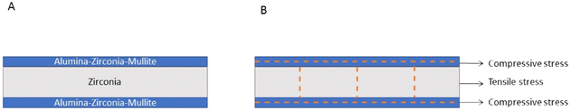
2.3.1. Residual stress determination. The samples were coated symmetrically on both sides to identify compressive residual stress in the surface layer (Fig. 1A and B). It is known that the tensile stress and compressive stress in the cross-section of the coated samples are balanced, so the following equation can be derived:
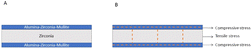 |
| | Fig. 1 (A) Schematic diagram of prestressed ceramic design. (B) Stress state of prestressed ceramics. | |
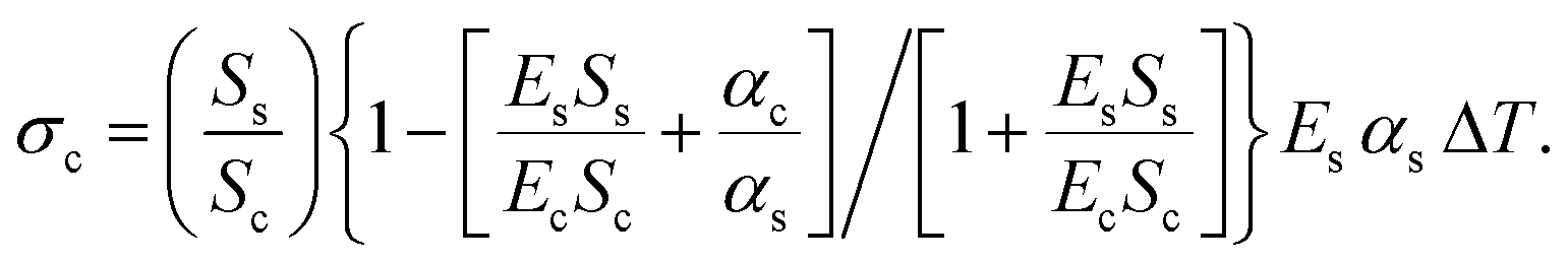
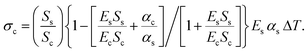
The residual stress in the coating can be determined according to the cross-sectional area ratio of the substrate to the coating, and the corresponding Young's modulus and CTE, using the following equation:
| |
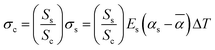 | (2) |
where
σc,
Ss,
Sc,
Es,
αs,
![[small alpha, Greek, macron]](https://www.rsc.org/images/entities/i_char_e0c2.gif)
and Δ
T are the compressive residual stress of the coating, cross-sectional area of the substrate, cross-sectional area of the coating, Young's modulus of the substrate, CTE of the substrate, and CTE of the composite, respectively. Δ
T represents the difference between the brittle–ductile transformation temperature and room temperature. The brittle–ductile transformation temperature is almost 2/3 of the sintering temperature. However, material characteristics instead of uncertain factors can be used to precisely assess residual stress in coatings. Therefore, the CTE of the composite can be represented as a function of the CTE of the coating material by the following equation:
| |
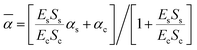 | (3) |
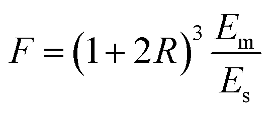
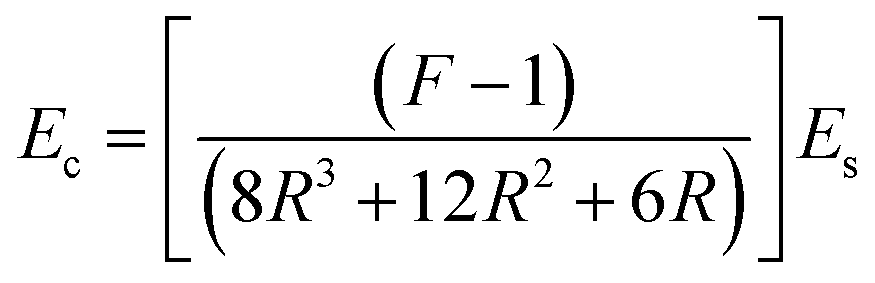
and the Young's modulus of coating materials can be expressed as follows:
| |
 | (4) |
| |
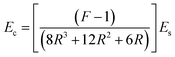 | (5) |
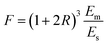
where
F,
Em, and
R are the ratio of deflection of the substrate, the Young's modulus of the composite and composite, and the ratio of the thickness of the coating and substrate, respectively. Consequently, the compressive residual stress can be expressed as follows:
| |
 | (6) |
As
eqn (6) indicates, the theoretical value of residual stress is related to the Young's modulus, CTE, the cross-sectional ratio of coating and substrate, and equivalent temperature. The cross-sectional area ratio is the only variable factor in
eqn (6) by which to determine the residual stress when the fabrication process and materials of the coating and substrate are unchanged.
4
2.3.2. Microstructure and X-ray diffraction. Scanning electron microscopy (SEM) (Quanta 250 FEG, FEI Company, USA) was used to inspect the growth morphology and crystal size of the sintered samples. In addition, optical microscopy (VHX-970F, KEYENCE, Japan) was used to inspect the regularity of the samples and measure the thickness of the coating. The distribution of Si in the coating material was determined using an energy-dispersive X-ray spectrometer (EDS) (EMAX, HORIBA, Japan). The phase analysis of the sintered coating material was identified by X-ray diffractometry (XRD) (Ultima IV, Rigaku, Japan). The surface of the samples was scanned at a speed of 2° min−1 using Cu Kα radiation (2θ = 20°–80°).
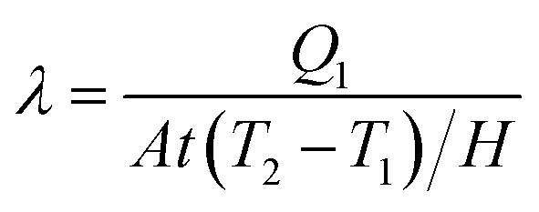
2.3.3. Thermal conductivity and coefficient of thermal expansion. It is known that the thermal conductivity of a sample with a thickness of H can be expressed using the following equation:| |
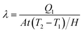 | (7) |
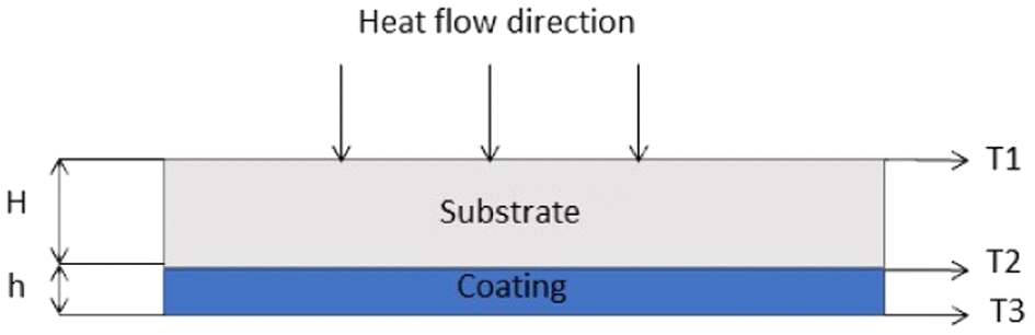
where A, Q1 and (T2−T1)/H are the thermal conductive area, heat flux during time t, and temperature gradient, respectively. A schematic illustration of the heat flow of the coated sample is shown in Fig. 2.
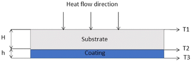 |
| | Fig. 2 Schematic diagram of heat flowing through three heat conduction areas with different temperatures under stable heat conduction. | |
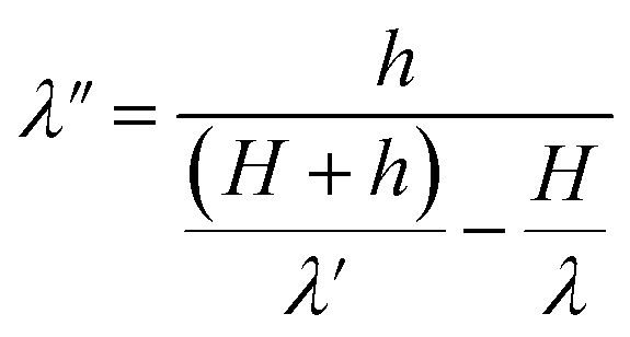
The thermal conductivity of the coating material can be calculated separately as follows:5
| |
 | (8) |
where
λ′ and
λ are the thermal conductivities of the coated samples and substrate, respectively, and
h and
H are the thickness of the coating and substrate, respectively. In order to reveal the thermal conductivity of the coating material, 0.9 mm thick substrates with different coating thicknesses were tested at room temperature to 1000 °C using a laser flash system (LFA 1000, Linseis, Germany). The thermal conductivity of the coating material was calculated using
eqn (8). The CTEs of coated and uncoated samples was determined using a horizontal dilatometer (L75PT, Linseis, Germany) from room temperature to 1200 °C, and the CTE of the coating material was determined using
eqn (3).
2.3.4. Mechanical properties. The coated and uncoated samples had dimensions of 2 mm × 4 mm × 20 mm after sintering. A universal test machine with a maximum load of 5000 N (UTM) (Model 45, MTS, USA) was used to test the flexural strength of the samples by 3-point bending. The samples were loaded at a displacement speed of 0.5 mm min−1, and a span of 16 mm was used to support the samples. Indentation testing was performed on the polished cross-section of coated samples using a Vickers hardness tester (HXD-2000TM/LCD, Shanghai Taiming Optical Instrument Co., Ltd., China) with a load of 2 kg, and the load was held for 15 s. The Young's modulus of the samples was measured using the impulse excitation of vibration method (ATSM E1876-09), and the Young's modulus of the coating material was calculated using the relative method introduced in eqn (4) and eqn (5).
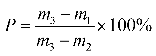
2.3.5. Archimedean porosimetry. The apparent porosity of the coated samples was determined according to Archimedean porosimetry. According to Archimedes' principle, the pores of the sample are filled with water, therefore causing it to correspondingly gain weight, where the increase in weight is proportional to the volume of the porosity. Three states of sample weight were determined, which were dry mass (m1), soaked mass (sample was boiled in water for 3 h, m3) and suspended mass (m2). The apparent porosity (P) of the sample was then calculated from these masses as:| |
 | (9) |
3. Results and discussion
3.1. Microstructure and X-ray diffraction
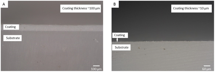
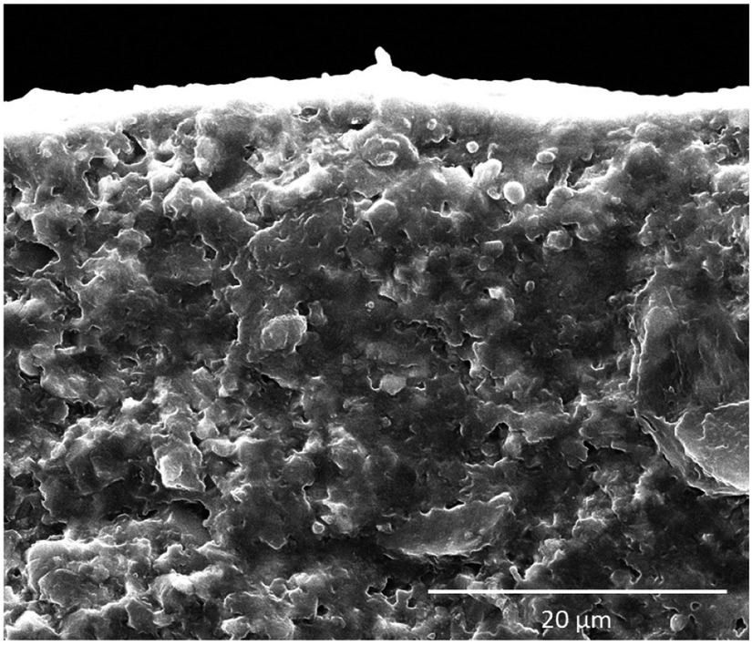
In this study, the manufacturing method produces a thin, uniform and flat coating with expected thickness, as shown in Fig. 3. The sizes of zirconia and alumina particles in the coating material are around 0.9 μm and 3.2 μm, respectively, and the results are shown in Fig. 4.
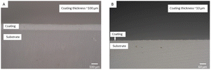 |
| | Fig. 3 Micrographs show the sintered flawless coatings manufactured by brushing. (A) 100 μm coating thickness. (B) 10 μm coating thickness. | |
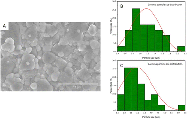 |
| | Fig. 4 Size of the alumina and zirconia particles in the coating material. (A) SEM image of the coating material. (B) Diagram of the probability distribution of size of zirconia particles. (C) Diagram of the probability distribution of the size of the alumina particles. | |
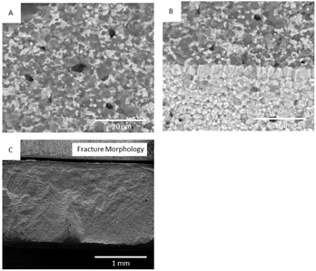
Compressive residual stress is not the only factor to enhance the strength of the zirconia substrate in this study. The mechanism of dispersion strengthening is another factor by which to achieve enhancement. Fig. 5A shows that the zirconia particles are uniformly distributed among the alumina particles. The zirconia particles act as a second phase, leading to a “pinning effect’’, resulting in the restriction of grain boundary migration and grain growth of the alumina particles. The fracture morphology of prestressed zirconia greatly fluctuates (Fig. 5C), and also shows an uneven fracture surface and tortuous crack propagation path. Furthermore, the fracture type in the compressive layer is highly distinct compared to that in the substrate. The compressive layer mainly shows transgranular fracture, and an intergranular and transgranular mixed fracture type is observed in the substrate, as shown in Fig. 5B. This fracture morphology in prestressed ceramics is not consistent with that of conventional ceramics. This is strongly considered to be the compressive residual stress that exists in the surface layer. For prestressed ceramics, the great magnitude of compressive residual stress in the surface layer could maintain tetragonal zirconia at room temperature. When the samples experience external stress, the tetragonal zirconia can be transformed into monoclinic zirconia, and such transformation involves ∼4% volume expansion. Volume expansion normally occurs along the direction of external stress, so microcracks are most likely to occur perpendicular to the direction of external stress. Consequently, the microcracks propagate through the grain and meet the main cracks with the presence of external stress, forming transgranular fractures through the alumina grain. The presence of residual compressive stress makes the interface between the crystals strongly bond and restricts grain growth, so the external stress does not easily damage the interface between the fine grains, that is, greater external stress is required to break the firm bonding of the crystals.
 |
| | Fig. 5 Electron microscopy of coated samples after sintering. (A) Fracture surface at the coating material. (B) Fracture surface at the interface between the coating and substrate. (C) Fracture surface morphology of the overall view of the coated sample. | |
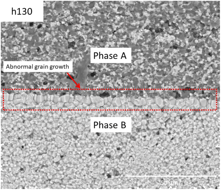
Fig. 6 shows the microstructure features at the interface of the thick sample, where it can be observed that abnormal grain growth occurs at the interface. The shape of grains at the interface is different from the grains at the compressive layer and substrate, and this can be explained as abnormal grain boundary migration caused by the completely different grain boundary energy of the two phases. Such a phenomenon also corresponds to the results observed in laminated ceramics.6 In addition, it was also found that the abnormal grain growth is significant with increasing layer thickness, which has also been observed in the literature.7–9 Abnormal grains have a significant effect on mechanical properties, in which the cracks are preferably propagated through the vertical abnormal grain boundary due to the weak and loose nature of such a structure. Decreasing the layer thickness can eliminate the formation of this structure, thus enhancing the mechanical properties.10–12
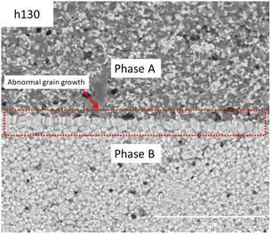 |
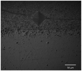
| | Fig. 6 Abnormal grain growth at the interface of the prestressed ceramic (h130). | |
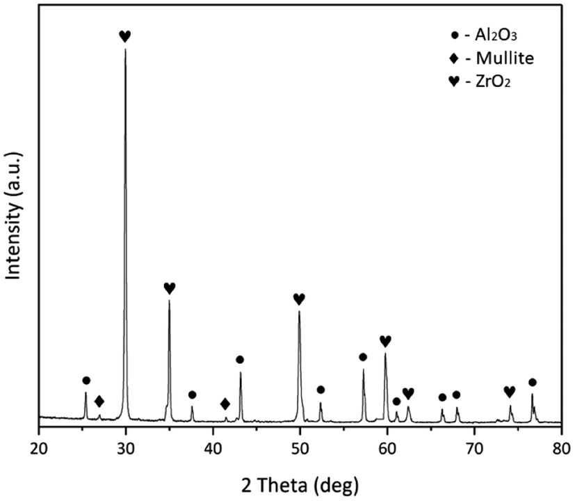
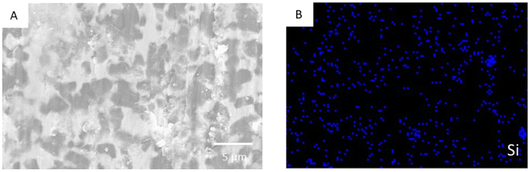
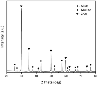
The X-ray diffraction pattern of the studied sample indicates that there is no peak for SiO2 detected in the diffraction pattern, and the peaks of mullite are observed, as labelled in Fig. 7. It is predicted that the Al2O3 is co-melted with SiO2 to form a liquid phase at high temperatures, thus mullite is formed during the cooling stage. The mullite distributed in the coating material can eliminate the localised micro-residual stress at grain boundaries caused by the completely different Young's modulus and CTE of alumina and zirconia, so as to avoid the possibility of delamination.13,14 The EDS results (Fig. 8) show that Si is uniformly distributed in the sintered coating material, meaning that no big dimensional inclusions formed.
 |
| | Fig. 7 X-ray diffraction pattern of the sintered coating material. | |
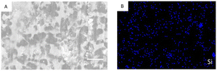 |
| | Fig. 8 EDS results of the sintered coating material. (A) Cross-section of the coating layer. (B) Distribution of Si in the coating material. | |
3.2. Mechanical properties and residual stress
The indentation of the polished cross-section of the coated sample is shown in Fig. 9. The direction of crack propagation indicates that compressive stress exists in the compressive layer of the coated samples. Moreover, the mean flexural strength of the uncoated samples was determined as 884.61 ± 99.25 MPa and that of the coated samples was determined as 1362.98 ± 30.29 MPa. The flexural strength was enhanced by ∼54.1% due to the compressive stress in the coating. From the results of the CTE testing, the ΔT, in this case, was determined around 1200 °C. The results related to residual stress are presented in Table 1.
 |
| | Fig. 9 Indentation photograph from an optical microscope of the indentation morphology of the prestressed ceramic at the coating layer, proving the existence of compressive stress in the coating. | |
Table 1 Parameters used for residual stress calculations and the results from experiments and calculations
| Samples |
hc, μm |
αs, 10−6 K−1 |
, 10−6 K−1 |
Em, GPa |
Es, GPa |
σc, MPa |
| h10 |
10 |
10.94 |
10.92 |
211.99 |
211.49 |
796 |
| h30 |
30 |
10.94 |
10.89 |
213.09 |
211.49 |
787 |
| h50 |
50 |
10.94 |
10.88 |
218.21 |
211.49 |
778 |
| h70 |
70 |
10.94 |
10.86 |
223.66 |
211.49 |
769 |
| h90 |
90 |
10.94 |
10.83 |
217.26 |
211.49 |
761 |
| h110 |
110 |
10.94 |
10.81 |
220.35 |
211.49 |
753 |
| h130 |
130 |
10.94 |
10.80 |
226.52 |
211.49 |
745 |
| h150 |
150 |
10.94 |
10.63 |
225.79 |
211.49 |
737 |
| h200 |
200 |
10.94 |
10.56 |
219.76 |
211.49 |
717 |
The compressive residual stress in this study is in agreement with literature reports (∼0.8 GPa), which show the applicability of eqn (6).15 The results of the Young's modulus of the coating material were calculated and are presented in Table 2, with there being no obvious dependence of it on the thickness of the coating. The mean of the Young's modulus of the coating material was 246.29 ± 16.38 GPa. The dispersion of Young's modulus can be explained by the inhomogeneity of the microstructure of the coating material, in which alumina has considerable difference to zirconia in terms of its elastic properties.
Table 2 Young's moduli of coating materials with different thicknesses calculated using the relative method
| Samples |
Ec (GPa) |
| h10 |
228.49 |
| h30 |
230.35 |
| h50 |
259.30 |
| h70 |
274.15 |
| h90 |
236.82 |
| h110 |
244.45 |
| h130 |
260.46 |
| h150 |
253.24 |
| h200 |
229.32 |
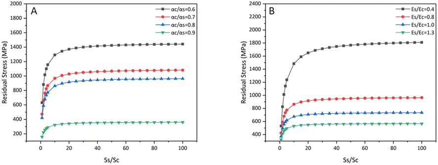
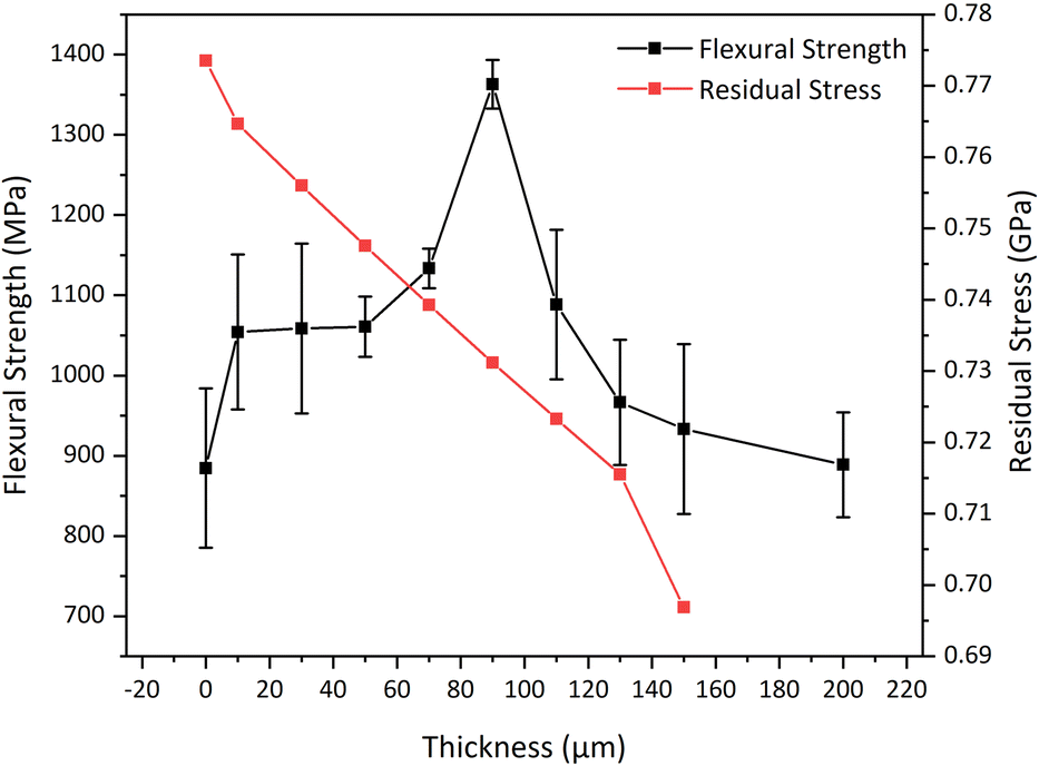
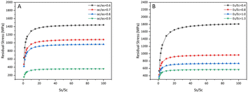
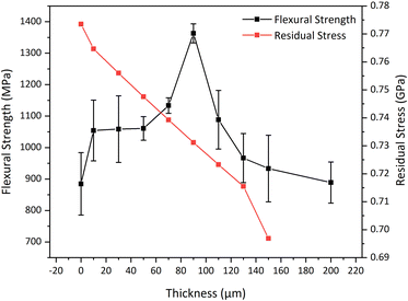
Based on eqn (6), the theoretical compressive residual stress in the coating gradually increases with increasing Ss/Sc, then a plateau occurs when Ss/Sc becomes greater than 20. In general, a uniformly coated layer shares the same width as the substrate, which means that the cross-sectional area ratio is equal to the thickness ratio of the coating and substrate. In other words, the residual stress in the coating decreases with increasing coating thickness, and is at its greatest when the coating is as thin as possible. In order to produce great compressive stress in the coating, the material must satisfy the following requirements: (a) αc/αs<1; (b) a relatively low Es/Ec value; (c) as high a Ss/Sc value as possible (Fig. 10). However, in this study, the samples with ∼90 μm show the greatest flexural strength, the samples with excessively thin coating thickness do not show the reinforcement effect as described in eqn (6), as shown in Fig. 11. Moreover, the thick coating samples show coating delamination and peeling, which also compromise its strength.
 |
| | Fig. 10 The theoretical compressive residual stress of prestressed ceramics as a function of (A) Es/Ec, and (B) αc/αs. | |
 |
| | Fig. 11 The flexural strength and theoretical compressive residual stress of samples with different coating thicknesses. | |
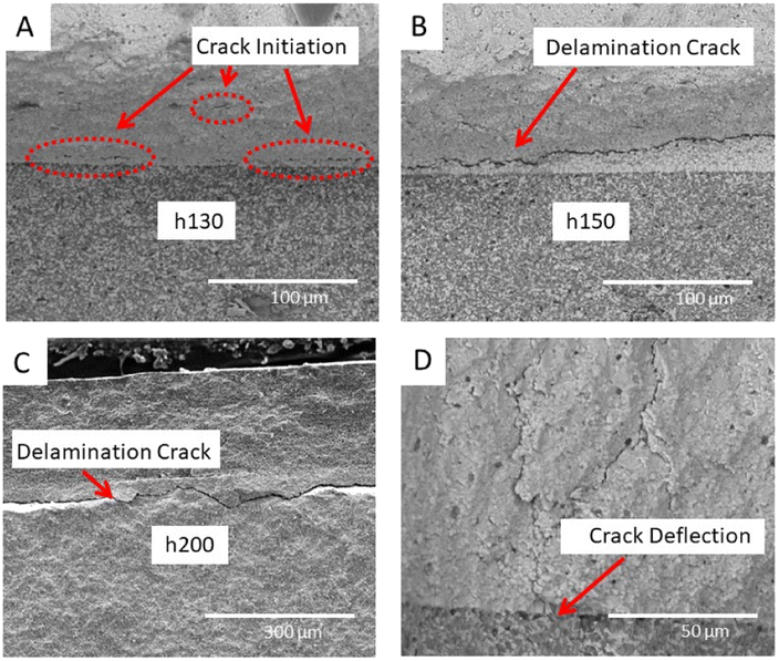
The surface compressive stress gradually increases along the thickness direction. The compressive stress reaches a maximum value when it approaches the interface layer, as is the case for the tensile stress. The tensile stress gradually decreases upon approaching half the thickness of the substrate, as shown in Fig. 12.16 Moreover, stress redistribution and relaxation occurred at the surface of the coating, namely, the “edge effect”.17 If the compressive layer is thin enough, high compressive stress should be generated theoretically according to eqn (6). Although the theoretical compressive stress of the thin compressive layer is high enough to block the cracks, the effective reinforcement is not pronounced in this study. Energy-dissipating mechanisms, such as crack deflection and crack bifurcation, are not obvious in thin coated materials, and the critical thickness of the compressive layer should be above ∼70 μm to block crack propagations, as reported.18 A critical thickness should be designed to improve the energy absorption capacity of the material to achieve reinforcement effect.19,20 In addition, thick samples (h130, h150, and h200) show delamination cracks at the interface, as shown in Fig. 13A–C, which severely compromise the strength of the samples. Such phenomenon is pronounced with the increasing thickness of the compressive layer. It is acknowledged that delamination is normally associated with excessive tensile stress distributed around the interface. This is in agreement with the calculations in a reported study, that the tensile stress increases with increasing coating thickness.21 When tensile residual stress overcomes the tensile strength of ceramics, delamination could occur at any time, and the tensile strength of ceramics is normally 40% to 60% of the flexural strength.22 It is interesting that the cracks perpendicular to the interface are hindered and deflected at the interface between the coating and substrate, as presented in Fig. 13D, so that the strength of the thick samples is still enhanced compared to uncoated substrate materials.
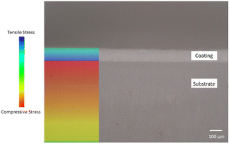 |
| | Fig. 12 The state of the residual stress displayed at the cross-section of prestressed ceramic. | |
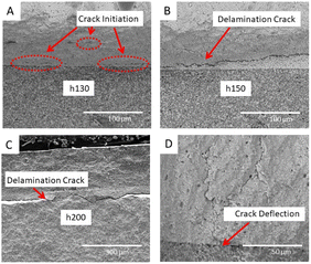 |
| | Fig. 13 Fracture surface of thick samples (h130, h150, and h200). (A), (B), and (C) Delamination cracks observed in samples with different coating thicknesses. (D) Perpendicular crack blocked by the compressive layer of prestressed ceramic. | |
3.3. Analysis of the porosity of the coated samples
In this study, the apparent porosity of samples with and without SiO2 was determined, with the results shown in Table 3. It is noticed that the prestressed ceramics manufactured in this study are relatively dense, and the apparent porosity does not exceed 0.6%. The apparent porosity of coated samples is not obviously influenced after the coating is applied. However, the thick samples are not as dense as the thin samples, the apparent porosity of the thick samples is almost double that of the thin samples. This is explained as the presence of cracks at the interface of the thick samples. Moreover, compared to the SiO2 containing samples, the samples without SiO2 in the coating material show relatively high apparent porosity. A small number of sintering aids, such as SiO2, MgO, and TiO2 when added to alumina can promote its densification. The addition of SiO2 forms mullites during the cooling stage of sintering, and the formed mullites are distributed among the alumina particles, avoiding the abnormal grain growth of alumina particles, thus removing the pores.23
Table 3 Results of bulk density and apparent porosity from Archimedean porosimetry
| Samples |
Bulk density (g cm−3) |
Apparent porosity (%) |
| Substrate |
6.01 |
0.23 |
| h10 |
5.98 |
0.23 |
| h30 |
5.90 |
0.27 |
| h50 |
5.97 |
0.27 |
| h70 |
5.90 |
0.21 |
| h90 |
5.87 |
0.21 |
| h110 |
5.95 |
0.26 |
| h130 |
5.88 |
0.28 |
| h150 |
5.78 |
0.45 |
| h200 |
5.77 |
0.59 |
| ns90 |
5.78 |
0.44 |
The flexural or tensile strength of the ceramic materials can be related to porosity, which is demonstrated by an exponential function:
| | |
σ = σ0exp(−BP)
| (10) |
where
σ is the flexural strength of the material with porosity
P,
σ0 is the flexural strength of the material with zero-porosity, and
B is a porosity dependence constant.
B in a range of 6–10 is used in most circumstances. Besides this, the Young's modulus of materials with pores can be expressed as:
| | |
E = E0(1 − P2/3)1.21
| (11) |
where
E and
E0 are the Young's modulus of the porous body and pore-free body, respectively. This equation is valid by assuming the pores found in the material are spherical. The porosity of the samples in this study has a negligible effect on the strength and Young's modulus, from the results of
eqn (10) and
eqn (11).
24,25
3.4. Thermal properties
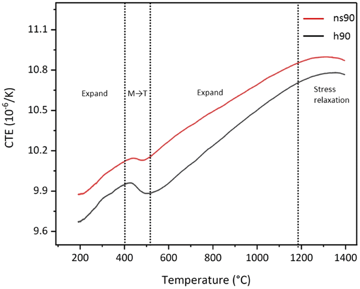
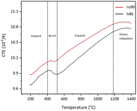
The CTEs of coating materials at 1200 °C with different thicknesses are demonstrated in Table 4. The mean CTE of the coating material at 1200 °C is 8.23 × 10⁻⁶ ± 7.62 × 10⁻⁷ K−1. The theoretical CTE of the coating material is lower than reported, so it can be explained as the formation of mullite lowering the CTE of the coating material.26 Fig. 14 shows the CTEs of h90 and ns90 with increasing temperature. It can be observed that there is a drop in the CTE at around 500 °C. This is predicted as a smaller number of monoclinic grains transform to tetragonal grains at around 500 °C, resulting in volume change. It has been reported that the monoclinic to tetragonal transformation temperature of zirconia can be progressively lowered by the addition of other compounds.26 When the temperature reaches about 1200 °C, the constraint of the coating on substrate is significantly weakened, in other words, the residual stress is relaxed or even vanishes, then the coated samples lose their constraints and expand freely.
Table 4 The calculated CTEs of coating materials with different thicknesses
| Samples |
αc (10−6 K−1) |
| h10 |
7.48 |
| h30 |
8.03 |
| h50 |
8.82 |
| h70 |
8.89 |
| h90 |
8.73 |
| h110 |
8.78 |
| h130 |
8.95 |
| h150 |
7.08 |
| h200 |
7.30 |
 |
| | Fig. 14 CTE changes of h90 and ns90 with increasing temperature. | |
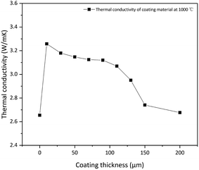
Fig. 15 shows the results of the thermal conductivity of coated samples at 1000 °C. It is interesting that the thermal conductivity of coated samples is higher than that of uncoated samples. It is known that alumina has a much higher thermal conductivity value than that of zirconia, therefore the content of alumina in the coating material correspondingly increases the thermal conductivity of the coated samples. The thermal conductivity of the coated samples at 1000 °C slightly decreases with an increase in the thickness of the coating, as shown in Fig. 15. The thermal conductivity of ceramic materials is mainly affected by lattice vibration (phonons) and radiation (photons). The presence of pores, defects, and grain boundaries can easily scatter photons and phonons, resulting in a decrease in thermal conductivity. In this study, the zirconia particles with small grain size are dispersed and pinned among alumina particles, which increases the number of grain boundaries in the coating, resulting in a great scattering effect, which consequently decreases the thermal conductivity of thick samples. When the coating thickness increases, the numbers of grain boundaries and defects statistically increase, further decreasing the thermal conductivity of the coated samples. In addition, the thermal conductivity of the thick samples h150 and h200 decreased considerably compared to relatively the thin samples. It has been discussed that the cracks are largely observed in h150 and h200 at the interface due to the excessive residual tensile stress, and these defects amplify the effect of scattering, leading to a significant decline in thermal conductivity.27,28
 |
| | Fig. 15 Thermal conductivity of coated samples with different thicknesses at 1000 °C. | |
In order to use eqn (8) properly, the following factors should be considered; (a) homogeneity of the coating, (b) thickness of the coating, and (c) interface defects. The thermal conductivity of alumina is very high at low temperatures, as the laser flash system is not that accurate due to the small thermal gradient across the coated samples at low temperatures, so h110 with fewer defects was used to calculate the thermal conductivity of the coating material at 1000 °C. The thermal conductivity of the coating material calculated using eqn (8) is 7.01 W mK−1. The lower value of the thermal conductivity is due to the formation of mullite.
3.5. Effect of SiO2 in the coating material on prestressed ceramics
The results of various properties of comparison samples are shown in Table 5. The flexural strength of ns90 is 1093.31 ± 143.50 MPa, which is decreased by 20.0% compared to that of h90. It was found that some of the comparison samples appeared to bend after sintering. The sintering shrinkage rate of the coating is dissimilar to that of the substrate, which means that highly localised stress can be found at the interface of the coated samples. Excessive localised stress can cause interlaminar cracks, delamination and deformation, etc. When SiO2 is introduced into the formula, a liquid phase can be formed in the later stage of sintering. The presence of a liquid phase can lead to creep and plastic deformation at the point where excessive localised stress exists, eliminating excessive localised stress. The CTE of the ns90 coating material was calculated using the relative method, and compared to the CTE of the h90 coating material it is closer to the CTE of the zirconia substrate. The change in the CTEs of the comparison samples results in a significant reduction in the compressive residual stress in the coating, which is 507.58 MPa. The reduction in the compressive residual stress of the comparison samples reduces the reinforcement effect accordingly. The thermal conductivity of the comparison samples is 3.05 W mK−1, lower than that of h90 (3.12 W mK−1). It is known that mullite is commonly used as a refractory material, and low thermal conductivity is an important characteristic by which to determine its performance as a thermal isolation material. When the formula of the coating does not contain SiO2, there is no mullite formation during sintering, which means that the thermal conductivity of the samples accordingly decreases. The thermal conductivity of the composite coating without SiO2 is calculated as 5.96 W mK−1, which is consistent with the simple rule of mixing results (6.22 W mK−1). The results calculated using the relative method show a reasonable agreement to the simple rule of mixing (eqn (12)). In this case, the simple rule of mixture is consisted of thermal conductivity of pure alumina and zirconia and their volume fraction.
Table 5 Flexural strength, CTE, Young's modulus, and thermal conductivity results of the comparison sample
| Properties |
ns90 |
Coating material |
| Flexural strength (MPa) |
1093.31 |
— |
| CTE (10−6 K−1) |
10.86 |
9.29 |
| Young's modulus (GPa) |
224.91 |
270.39 |
| Thermal conductivity at 1000 °C (W mK−1) |
3.05 |
5.96 |
| Compressive residual stress (MPa) |
507.58 |
— |
t has been reported that doping some SiO2 into alumina can reduce the sintering temperature to 50 °C–150 °C. Fig. 16 shows the SEM of the fracture surface of the comparison sample. The essential microstructure changes can be observed in Fig. 16. The samples without SiO2 require a higher sintering temperature to promote the advanced densification of the coating material. The sintering temperature can be reduced by adding SiO2 to make the sintering process easy to complete.29
 |
| | Fig. 16 The fracture surface of the comparison sample without SiO2. | |
4. Conclusions
As a result, the compressive stress layer can improve the strength of ceramics. The sample with a 90 μm thick coating has the highest strength among the series of samples. When the thickness of the compressive layer reaches 200 μm, the reinforcement of the compressive layer is almost eliminated due to abnormal grain growth and delamination cracks. Moreover, the very thin coating also shows no obvious improvement in the strength of ceramics, because cracks cannot be deflected or bifurcated by a thin coating. The CTE and Young's modulus of the coating material were determined using the relative method as 246.29 ± 16.38 GPa and 8.23 × 10⁻⁶ ± 7.62 × 10⁻⁷ K−1, respectively. Mullite is formed during the sintering process, according to the XRD results. The presence of mullite reduces the concentration of localised stress and the CTE of the coating material, resulting in an improvement in strength. The thermal conductivity of the coated sample is slightly increased compared to that of uncoated zirconia, and the thermal conductivity of the coating material was determined as 7.03 W mK−1. Besides this, the overall performance of samples without the addition of SiO2 is inferior to that of samples with SiO2 addition.
Conflicts of interest
There are no conflicts to declare.
Acknowledgements
This work was supported by the National Natural Science Foundation of China [grant number 52032011] and the National Key R&D Program of China [grant number 2021YFB3702300].
References
- H. Moon and F. F. Lange, Strengthening with a uniform compressive layer produced by a dip-coating: A study of processing variables, J. Am. Ceram. Soc., 2010, 93, 264–1269 Search PubMed.
- W. J. Clegg, K. Kendall and N. Alford, et al., A simple way to make tough ceramics, Nature, 1990, 347, 455–457 CrossRef CAS.
- A. J. Sánchez-Herencia, C. Pascual and J. He, et al., ZrO2/ZrO2 layered composites for crack bifurcation, J. Am. Ceram. Soc., 2004, 82, 1512–1518 CrossRef.
- Y. Bao, F. Kuang and Y. Sun, et al., A simple way to make pre-stressed ceramics with high strength, Journal of Materiomics, 2019, 5, 657–662 CrossRef.
- D. Zheng, Y. Bao and D. Wan, et al., Determining the thermal conductivity of ceramic coatings by relative method, Int. J. Appl. Ceram. Technol., 2019, 16, 2299–2305 CrossRef CAS.
- Q. Zhou, B. Xue and S. Gu, et al., Competitive grain growth behavior in laminated ceramic composites: An insight from numerical simulation, Ceram. Int., 2021, 47, 13783–13788 CrossRef CAS.
- B. K. Jang and H. Matsubara, Microstructure of nanoporous yttria-stabilized zirconia films fabricated by EB-PVD, J. Eur. Ceram. Soc., 2006, 26, 1585–1590 CrossRef CAS.
- D. E. Wolfe, J. Singh and R. A. Miller, et al., Tailored microstructure of EB-PVD 8ysz thermal barrier coatings with low thermal conductivity and high thermal reflectivity for turbine applications, Surf. Coat. Technol., 2005, 190, 132–149 CrossRef CAS.
- Y. Meng, W. Qiang and J. Pang, Fabrication and microstructure of laminated HAP–45S5 bioglass ceramics by Spark Plasma Sintering, Materials, 2019, 12, 484 CrossRef CAS PubMed.
- S. Biswas, D. Schwen and H. Wang, et al., Phase field modeling of sintering: Role of grain orientation and anisotropic properties, Comput. Mater. Sci., 2018, 148, 307–319 CrossRef.
- Y. Yang, T. D. Oyedeji and P. Kühn, et al., Investigation on temperature-gradient-driven effects in unconventional sintering via non-isothermal phase-field simulation, Scr. Mater., 2020, 186, 152–157 CrossRef CAS.
- L. Du, S. Yang and X. Zhu, et al., Pore deformation and grain boundary migration during sintering in porous materials: A phase-field approach, J. Mater. Sci., 2018, 53, 9567–9577 CrossRef CAS.
- G. Shi, Z. Wang and J. Liang, et al., NiCoCrAl/YSZ laminate composites fabricated by EB-PVD, Mater. Sci. Eng. A, 2011, 529, 113–118 CrossRef CAS.
- Z. Krzysiak, E. Gevorkyan and V. Nerubatskyi, et al., Peculiarities of the phase formation during electroconsolidation of Al2O3–SiO2–ZrO2 powders mixtures, Materials, 2022, 15, 6073 CrossRef CAS.
- V. S. Seesala, R. Rajasekaran and P. V. Vaidya, et al., Functional gradient coating of alumina on net shaped zirconia implant: Improved strength, aging resistance, and role of residual stress, J. Eur. Ceram. Soc., 2022, 42, 5932–5942 CrossRef CAS.
- G. Portu, L. Micele and Y. Sekiguchi, et al., Measurement of residual stress distributions in AlO/3Y-TZP multilayered composites by fluorescence and Raman microprobe piezo-spectroscopy, Acta Mater., 2005, 53, 1511–1520 CrossRef.
- V. Sergo, D. M. Lipkin and G. D. Portu, et al., Edge stresses in alumina/zirconia laminates, J. Am. Ceram. Soc., 2005, 80, 1633–1638 CrossRef.
- A. K. Hofer, R. Walton and O. Ševeček, et al., Design of damage tolerant and crack-free layered ceramics with textured microstructure, J. Eur. Ceram. Soc., 2020, 40, 427–435 CrossRef CAS.
- R. Bermejo, Y. Torres and C. Baudín, et al., Threshold strength evaluation on an Al2O3–ZrO2 multilayered system, J. Eur. Ceram. Soc., 2007, 27, 1443–1448 CrossRef CAS.
- I. Nicolaidis, J. Gurauskis and C. Baudín, et al., Forming of ceramic laminates comprising thin layers of a few particles, J. Am. Ceram. Soc., 2008, 91, 2124–2129 CrossRef CAS.
- B. Chen, P. Ding and Z. Zhou, Structural design and performance of Al2O3/laminated ceramics, J. Chin. Ceram. Soc., 2001, 29, 0454–5648 Search PubMed.
- Z. Chlup, L. Novotná and F. Šiška, et al., Effect of residual stresses to the crack path in alumina/zirconia laminates, J. Eur. Ceram. Soc., 2020, 40, 5810–5818 CrossRef CAS.
- D. C. Fabris, M. B. Polla and J. Acordi, et al., Effect of MgO·Al2O3·SiO2 glass-ceramic as sintering aid on properties of Alumina Armors, Mater. Sci. Eng. A, 2020, 781, 139237 CrossRef CAS.
- A. Chowdhury, Constitutive modelling and weibull statistical analysis for the porosity - mechanical property correlations in 3% yittria-stabilized zirconia system, Int. J. Refract. Met. Hard Mater., 2018, 70, 246–252 CrossRef CAS.
- A. Das and D. Pamu, A comprehensive review on electrical properties of hydroxyapatite based ceramic composites, Mater. Sci. Eng. C, 2019, 101, 539–563 CrossRef CAS PubMed.
- H. G. Scott, Phase relationships in the yttria-rich part of the Yttria-zirconia system, J. Mater. Sci., 1977, 12, 311–316 CrossRef CAS.
- N. P. Bansal and D. Zhu, Thermal conductivity of zirconia–alumina composites, Ceram. Int., 2005, 31, 911–916 CrossRef CAS.
- X. Song, M. Xie and F. Zhou, et al., High-temperature thermal properties of yttria fully stabilized zirconia ceramics, J. Rare Earths, 2011, 29, 155–159 CrossRef CAS.
- V. Kulyk, Z. Duriagina and A. Kostryzhev, et al., Effects of sintering temperature and yttria content on microstructure, phase balance, fracture surface morphology, and strength of yttria-stabilized zirconia, Appl. Sci., 2022, 12, 11617 CrossRef CAS.
|
| This journal is © The Royal Society of Chemistry 2023 |
Click here to see how this site uses Cookies. View our privacy policy here. 
 Open Access Article
 This Open Access Article is licensed under a Creative Commons Attribution-Non Commercial 3.0 Unported Licence
 *ab,
Kuilin Lvab,
Yiwang Bao*ab,
Yuan Tianab and
Detian Wanab
*ab,
Kuilin Lvab,
Yiwang Bao*ab,
Yuan Tianab and
Detian Wanab