
 Open Access Article
 This Open Access Article is licensed under a Creative Commons Attribution-Non Commercial 3.0 Unported Licence
Washable and stretchable fiber with heat and ultraviolet color conversion
Jonguk Yang and
Sanghyun Ju *
*
Department of Nanoengineering, Kyonggi University, Suwon 16227, Gyeonggi-Do, South Korea. E-mail: shju@kgu.ac.kr
First published on 10th August 2022
Abstract
Wearable fabric-type color conversion sensors are very effective in quickly expressing danger or warnings to people. In particular, they can visually show information regarding the external environment, such as its temperature or ultraviolet (UV) intensity. However, a wearable sensor worn on the human body should maintain its sensing performance without deterioration even when exposed to various external stimuli, such as the repeated movements caused by human activity, sweat, and washing. In this study, thermochromic and UV photochromic fibers were fabricated to maintain stable color conversion functionality in response to temperature and UV irradiation even after continuous tensile-shrinkage, exposure to sweat and detergent solution. The thermochromic or UV photochromic materials were coated on the inside and outside of strands constituting a highly elastic spandex fiber. By adding polydimethylsiloxane to the color-changing material, the physical and chemical stability of the color-conversion thin film coated on the strand increased. The fabricated thermochromic fiber had a blue-green color and changed to white as the temperature increased, whereas the fabricated UV photochromic fiber was white and changed to purple as the UV intensity increased. In addition, the color conversion coating film was not lost even when exposed to repeated stretching and sweat/washing solutions, and a stable color-change reactivity was maintained. The thermochromic and UV photochromic fibers introduced in this study are expected to contribute to the commercialization of wearable colorimetric sensors by solving the problems regarding the physical stimulation and washing stability of existing coating-type color conversion fibers and textiles.
1. Introduction
Wearable environmental monitoring devices can be used to provide information on continuous environmental changes and can record data on ultraviolet (UV) light, temperature, humidity, chemicals harmful to the human body, and mechanical deformation.1–6 Among these parameters, UV rays and the temperature are essential for diagnosing environmental factors that can affect human activity. For instance, prolonged exposure to UV rays can damage the skin and cause diseases such as burns, aging, and cancer. In addition, exposure to high-temperature environments can cause heat-related illness such as heatstroke, exhaustion, cramps, and fatigue.7–12 UV and temperature sensors have been developed using various types of electrochemical analyses comprising conductive fillers such as metal nanowires, nanoparticles, and carbon materials on flexible substrates.13–17 However, these sensors have limitations in their application to wearable devices owing to problems such as complicated fabrication methods, relatively bulky analytical instruments, and the use of external power sources.18–20Because the color-change-sensitive material in the colorimetric sensor reacts with various analytes to change color, it is very effective in monitoring various external environmental changes, such as UV rays, temperature, humidity, and harmful chemicals. In particular, a fiber-based colorimetric sensor is light, flexible, and can be easily applied to products such as lab coats and safety protection devices (as well as daily necessities such as hats and gloves), as it can secure breathability and mechanical stability when made of fabric.21 In addition, they can be popularized and widely distributed owing to their simple fabrication method, high accessibility, ease of use, and low cost.22–24 At present, to bond the sensitive material to the fiber surface, the method of simply applying and coating a sensitive material solution or a solution mixed with a binder material on the fiber is the most commonly used.25–28 However, in such cases, because the physical bond between the sensitive material and fiber is weak, there is a possibility that the sensitive material may be lost owing to leaching in sweat or a washing solution. Therefore, it is necessary to study a fiber-based colorimetric sensor able to maintain the sensitivity of the sensitive material as it is and to maintain a stable color change without loss of the sensitive material, even during repeated stretching and exposure to sweat or a washing solution.
In this study, we developed a method for easily and uniformly embedding thermochromic and photochromic materials able to react quickly to heat and UV light on multiple strands of spandex fiber. A coating solution was prepared in which polydimethylsiloxane (PDMS), a thermally crosslinked polymer, was added as a binder so that the color-conversion material could be stably fixed on the spandex fiber surface. PDMS can effectively immobilize sensitive materials to a crosslinked polymer chain when the crosslinking reaction is conducted by heat. In addition, by suppressing the contact between the sensitive material and water using the hydrophobic properties of the PDMS polymer chain, it was possible to minimize the loss of the sensitive material and secure a stable sensitivity. The fabricated highly stretchable thermochromic and UV photochromic fibers were able to reversibly change color from blue-green to white (for the thermochromic fiber) and from white to purple (for the UV photochromic fiber) depending on the temperature and exposure to UV light, respectively. In addition, even when exposed to repeated stretching and sweat/washing solutions, the sensitive material fixed to the PDMS polymer chain was not lost, maintaining a stable color-change reactivity.
2. Experimental
2.1 Fabrication of thermochromic and UV photochromic fibers
Thermochromic microcapsules (1–5 μm diameter; TP31GR, NANO I & C) and UV photochromic microcapsules (1–5 μm diameter; PPRE, NANO I & C) were used as the colorimetric materials for responding to temperature and UV light. To prepare the colorimetric solution, 5 wt% of a colorimetric material responsive to temperature or UV was added to 2-propanol (IPA; 99.5%, DAEJUNG), and sonication was performed for 10 min to ensure that the material was completely dispersed. Then, 0.5 wt% of the PDMS mixture obtained by mixing the PDMS prepolymer and a curing agent (Sylgard 184, The Dow Chemical Company) in a mass ratio of 10![[thin space (1/6-em)]](https://www.rsc.org/images/entities/char_2009.gif) :1 was added. The spandex fiber (diameter of ∼450 ± 15 μm, Hyosung TNC Co. Ltd) was immersed in the colorimetric solution, sonicated for 30 min, and then taken out and dried at room temperature for 2 h, thereby the colorimetric materials were embedded on the inner and outer strands of the spandex fiber. The colorimetric temperature and UV sensors were fabricated by cross-stitching thermochromic or UV photochromic fibers on a 10 × 15 mm2 polyester textile (WW-3009, KM). A temperature-sensitive discoloration test of the thermochromic fiber and the colorimetric temperature sensor was performed in a temperature environment of 25–37 °C using a vacuum oven (SH-VDO-08NG, SH Scientific). The photochromic test of the UV photochromic fiber and the colorimetric UV sensor was conducted by irradiating a UV light source of 0–2.5 mW cm−2 at 0.5 mW cm−2 steps using a UV cure machine (SLA-0505 AF, JUEUN UV TECH CO., Ltd) with a center wavelength of ∼365 nm. A conventional laundry detergent (Power Soda Bubble Bright, Mukunghwa, South Korea) was used for the washing stability test.
:1 was added. The spandex fiber (diameter of ∼450 ± 15 μm, Hyosung TNC Co. Ltd) was immersed in the colorimetric solution, sonicated for 30 min, and then taken out and dried at room temperature for 2 h, thereby the colorimetric materials were embedded on the inner and outer strands of the spandex fiber. The colorimetric temperature and UV sensors were fabricated by cross-stitching thermochromic or UV photochromic fibers on a 10 × 15 mm2 polyester textile (WW-3009, KM). A temperature-sensitive discoloration test of the thermochromic fiber and the colorimetric temperature sensor was performed in a temperature environment of 25–37 °C using a vacuum oven (SH-VDO-08NG, SH Scientific). The photochromic test of the UV photochromic fiber and the colorimetric UV sensor was conducted by irradiating a UV light source of 0–2.5 mW cm−2 at 0.5 mW cm−2 steps using a UV cure machine (SLA-0505 AF, JUEUN UV TECH CO., Ltd) with a center wavelength of ∼365 nm. A conventional laundry detergent (Power Soda Bubble Bright, Mukunghwa, South Korea) was used for the washing stability test.
2.2 Characterization and analysis of thermochromic and UV photochromic fibers
The surface and cross-sections of the thermochromic and UV photochromic fibers were confirmed by field-emission scanning electron microscopy (FE-SEM; S-4800, Hitachi). The thermal properties of the thermochromic and UV photochromic fibers were analyzed using thermogravimetric analysis (TGA; TGA/DSC1, Mettler Toledo) in the temperature range of 25–800 °C. The mechanical properties were measured using a thermal mechanical analyzer (TMA; TMA7000, Hitachi). The color changes of the thermochromic and UV photochromic fibers and the colorimetric temperature and UV sensors were analyzed using RGB values and a CIE L*a*b* (International Commission of Illumination) color space analysis.29,30 The thermochromic and UV photochromic fibers and the colorimetric temperature and UV sensors were photographed and imaged under the same lighting conditions, and then the images were analyzed with Adobe Photoshop CS4 to extract the RGB values and CIE L*a*b* color space values of the image colors. The RGB value indicates the intensity of the red, green, and blue colors in the color space. In CIE L*a*b*, the lightness of the photo image, L* is the color change from 0 (black) to 100 (white), a* is the color from ranging from red (+) to green (−) change, and b* represents the color change from yellow (+) to blue (−). The total color difference (ΔE) was calculated as follows:
In the above, ΔL* = L − L0; Δa* = a − a0; and Δb* = b − b0. The standard samples (L0, a0, b0) represent the measurements of the thermochromic and UV photochromic fibers and the colorimetric temperature and UV sensors under the initial conditions.29,31
3. Results and discussion
The temperature and UV rays are important environmental factors directly related to human health. Because high temperatures can have serious adverse effects on the human body, a weather warning is issued if the sensible temperature rises sharply or if a heat wave continues. In particular, a heat wave advisory is issued, as it is judged that serious damage may occur if the high temperature continues for two days above 33 °C.32 Moreover, long-term exposure to UV rays from the outside may also cause serious health problems, including skin cancer, and various safety standards for UV exposure have been developed. According to the American Conference of Governmental Industrial Hygienists (ACGIH 2004) guidelines, one of the most commonly used guidelines, the UV-A exposure intensity should not exceed 1 mW cm−2 for a long-term exposure of more than 1000 s.33By attaching colorimetric textile sensors made of thermochromic and UV photochromic fibers to an easily conspicuous part (or whole) of clothes, it is possible to quickly and easily observe external temperature changes and UV intensity. Fig. 1(a) is a schematic diagram showing the real-time color change of a textile-based colorimetric sensor with thermochromic and UV photochromic fibers applied to a sleeve when exposed to an external high temperature and UV rays. In this study, a washable and stretchable fiber-based colorimetric textile sensor capable of color conversion under heat or UV exposure was fabricated by uniformly embedding the thermochromic or UV photochromic materials, respectively, in a solution dispersed in multiple strands of highly elastic spandex fibers. The thermochromic material used in this study is a lactone-based material in which a lactone ring-opening/closing reaction occurs when the temperature increases. The lactone ring-opening structure at low temperature exhibits a colored state, and the lactone ring-closing structure becomes a colorless state when the temperature increases.34–36 The UV photochromic material used in this study is a spiropyran-based material that undergoes transformation from a spiropyran structure to a merocyanine structure when exposed to UV rays. In the absence of UV rays, the spiropyran structure appears a colorless state, and the merocyanine structure that appears when exposed to UV appears the colored state.37–42 The colorimetric temperature sensor was initially blue-green but turned white when exposed to temperatures above 35 °C. The colorimetric UV sensor was initially white, but turned purple when exposed to UV over 2 mW cm−2. The color-change colorimetric temperature and UV sensors were restored to their initial states of blue-green (colorimetric temperature sensor) and white (colorimetric UV sensor) when they are out of the high temperature and UV exposure environments, respectively. As a result, it was possible to reversibly sense temperature changes and UV intensity changes in the external environment through the color changes.
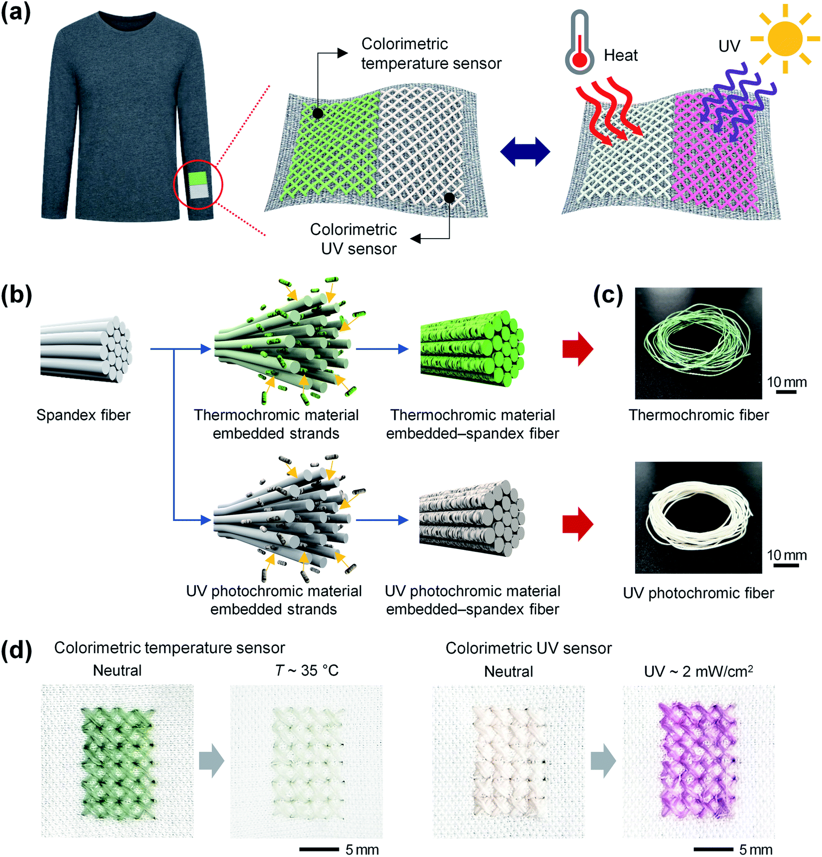 | ||
| Fig. 1 Thermochromic and ultraviolet (UV) photochromic fibers for wearable sensors. (a) Schematic diagram showing the colorimetric temperature and UV sensors applied by weaving thermochromic and UV photochromic fibers to the sleeve of the clothing, and showing the color changes when exposed to an external high temperature and UV. (b) Schematic diagram of the fabrication process of the thermochromic and UV photochromic fibers. (c) Photo images of the fabricated thermochromic and UV photochromic fibers. (d) Color-change images of the textile-based colorimetric sensors woven with thermochromic and UV photochromic fibers. The colorimetric temperature sensor changes from blue-green to white, and the colorimetric UV sensor changes from white to purple. | ||
Fig. 1(b) shows a schematic of the fabrication process of the thermochromic and UV photochromic fibers. Spandex fibers with high elasticity were used as a matrix for coating a colorimetric material able to react to temperature and UV color changes. The spandex fiber comprised approximately 56 strands in the form of a bundle adhered to the surface owing to the stickiness of the surface.43 In general, a spandex fiber consists of a chemically rigid polyurethane block and a soft polyglycol block. The rigid blocks are crystalline and form strong hydrogen bonds with adjacent molecules to improve the fiber's strength. The soft blocks (with an amorphous and flexible structure) have a low bonding strength with adjacent molecules, thereby imparting elongation and elasticity to the fiber.44 A colorimetric solution of IPA with 5 wt% of colorimetric material (thermochromic or UV photochromic microcapsules) and PDMS (0.5 wt%) was coated on a spandex fiber. The PDMS was used to stably fix the colorimetric materials to the spandex strands. When a spandex fiber is immersed in a colorimetric solution using IPA as the solvent, the multi-strands of the spandex fiber swell, and the colorimetric solution easily penetrates into the spaces between the strands. As a result, the colorimetric materials are coated on the surfaces of the strands located inside the fiber, as well as the exposed strands on the outside of the fiber. In addition, as the swollen strands contract during the drying process, the colorimetric materials embedded therein are additionally adhered to so that they are not separated from the fibers, even by external stimuli or continuous fiber stretching. The fabricated thermochromic and UV photochromic fibers were blue-green and white, respectively, and could be coated uniformly, regardless of their length (Fig. 1(c)). Fig. 1(d) shows the color-change results of the textile-based colorimetric sensors woven with the thermochromic and UV photochromic fibers. The colorimetric temperature sensor changed from blue-green to white after 4 min of exposure to 35 °C. The color of the colorimetric UV sensor changed from its initial white to purple after exposure to a UV intensity of 2 mW cm−2 for 10 s.
Fig. 2(a) shows a photograph and FE-SEM images of the thermochromic fiber. As the thermochromic microcapsules, (i.e., the colorimetric material that responds to temperature) were embedded, the pristine spandex fiber, which was white, changed to blue-green. To confirm that the thermochromic microcapsules were uniformly coated on the inside of the strands constituting the fabricated thermochromic fiber, the outside strands were removed, and the surfaces of the inside strands were observed using FE-SEM. As shown in the figure, the thermochromic microcapsules were uniformly coated on the inner strands as well as the outer strands of the fiber. The diameter of the thermochromic fiber coated with the thermal-responsive colorimetric material was ∼445 ± 16 μm, i.e., not significantly different from the diameter of the pristine spandex fiber (∼450 ± 15 μm).
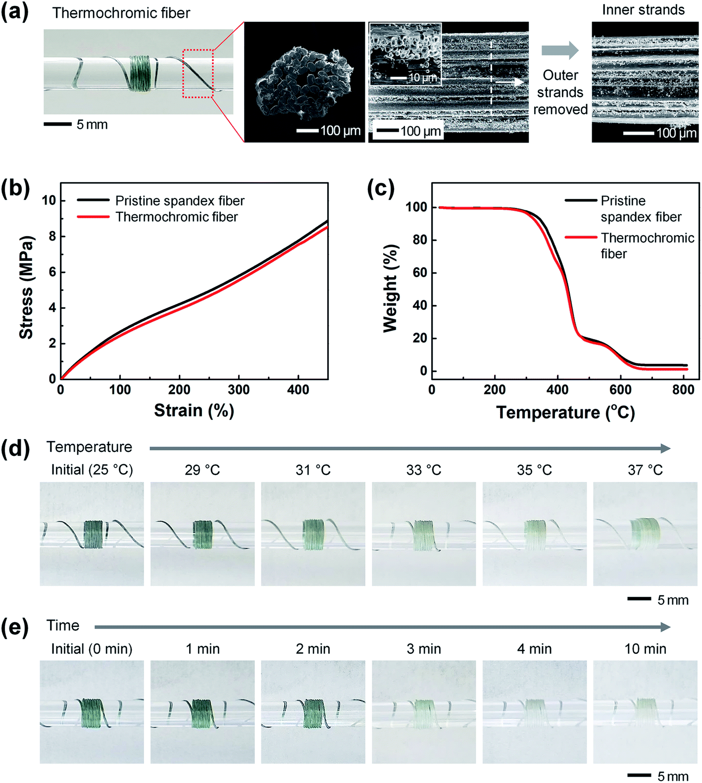 | ||
| Fig. 2 Thermochromic fiber. (a) Photo image of a thermochromic fiber wound on a glass rod and field-emission scanning electron microscopy (FE-SEM) images of a thermochromic fiber. (b) Strain–stress and (c) thermogravimetric analysis (TGA) curves of the pristine spandex and thermochromic fibers. (d) Color-change images of the thermochromic fiber exposed to six different temperatures (25, 29, 31, 33, 35, and 37 °C) for 4 min. (e) Color-change images of thermochromic fiber according to exposure time (0, 1, 2, 3, 4, and 10 min) at a temperature of 37 °C. | ||
Fig. 2(b) shows the mechanical properties (strain–stress curve) of the pristine spandex and thermochromic fibers using the TMA equipment. Both the pristine spandex and thermochromic fibers did not break when stretched from an initial length of ∼0.9 mm to 5 mm (450%), the maximum length allowed by the measuring instrument. In addition, even after embedding the colorimetric material, the stress value was ∼8.7 MPa under a 450% elongation, showing similar results. This indicates that the embedded colorimetric material does not affect the mechanical properties of the spandex fiber. Fig. 2(c) shows the results from the TGA in the temperature range of 25–800 °C to determine the thermal properties of the pristine spandex and thermochromic fibers. Both pristine spandex and thermochromic fibers started thermal decomposition at a temperature of approximately 250 °C and showed similar results with complete degradation at a temperature of ∼650 °C. This indicates that the arrangement and crystallinity of the polymer chains constituting the spandex fiber are not deformed by the colorimetric material. Fig. 2(d) shows the color-change characteristics of the thermochromic fiber after exposure to a heat source. After the thermochromic fiber was wound on a transparent glass rod, a color change of the thermochromic fiber was observed while the temperature was increased from 25 °C to 37 °C. The thermochromic fiber, which initially showed a blue-green color (R:G:B = 123:136:130), began to show a noticeable color change at 33 °C and became white (R:G:B = 204:207:199) at 35 °C. Fig. 2(e) shows the results from confirming the reaction time of the thermochromic fiber. The initial blue-green thermochromic fiber gradually faded in color over time at a temperature of 37 °C, and turned completely white after ∼4 min.
Fig. 3(a) shows photographs and FE-SEM images of the UV photochromic fiber. As UV photochromic microcapsules, i.e., a white UV-responsive colorimetric material, were used for the opaque white pristine spandex fiber, the UV photochromic fiber also appeared white. To confirm that the UV photochromic microcapsules were uniformly coated on the inside of the strands constituting the fabricated UV photochromic fiber, the outside strands were removed and the surfaces of the inside strands were observed with FE-SEM. As shown in figure, it was confirmed that the UV photochromic microcapsules were uniformly coated on the inner strands as well as the outer strands of the fiber. The diameter of the UV photochromic fiber coated with the UV-responsive colorimetric material was ∼454 ± 12 μm, i.e., not significantly different from that of the pristine spandex fiber (∼ 450 ± 15 μm).
 | ||
| Fig. 3 UV photochromic fiber. (a) Photo image of a UV photochromic wound on a glass rod and FE-SEM images of a UV photochromic. (b) Strain–stress and (c) TGA curves of the pristine spandex and UV photochromic fibers. (d) Color-change images of UV photochromic fiber exposed to 6 different UV intensities (0, 0.5, 1, 1.5, 2, and 2.5 mW cm−2) for 10 s. (e) Color-change images of UV photochromic fiber according to exposure time (0, 2, 4, 6, 10, and 300 s) at a UV intensity of 0.5 mW cm−2. | ||
Fig. 3(b) and (c) show the mechanical and thermal properties of the UV photochromic fibers, respectively. As a result of TMA measurements, the UV photochromic fiber did not break even at elongations up to 450%, similar to the pristine spandex fiber, and the stress value was ∼8.7 MPa under elongation at 450%, showing similar results. In addition, as a result of an evaluation of thermal properties through the TGA analysis, thermal decomposition of the pristine spandex and the UV photochromic fibers started at a temperature of 250 °C, and showed a similar tendency to be completely degraded at a temperature of ∼650 °C. Thus, it was confirmed that the mechanical and thermal properties of the spandex fiber were maintained even after embedding the UV-responsive colorimetric material.
Fig. 3(d) shows the color change of the UV photochromic fibers after UV exposure. After winding the UV photochromic fiber on a transparent glass rod, the color change was confirmed by increasing the UV intensity to 2.5 mW cm−2 in steps of 0.5 mW cm−2. The UV photochromic fiber, which initially appeared white (R:G:B = 242:240:234), turned light purple at 0.5 mW cm−2, and gradually became darker and became purple at 2 mW cm−2 (R:G:B = 212:122:183). It is worth to note that the purple color remained at powers higher than 2 mW cm−2. Fig. 3(e) shows the results from confirming the reaction time of the UV photochromic fiber. The degree of color conversion over time was observed at a UV intensity of 0.5 mW cm−2. The color change of the UV photochromic fiber started to react rapidly within ∼2 s, the color gradually became darker with time, and the color was fully expressed after ∼10 s.
Because wearable sensors worn by humans are exposed to environments such as stretching, sweating, and washing, stable sensing characteristics are essential, even in these environments.45–47 To confirm whether the thermochromic and UV photochromic fibers stably maintained color conversion reactivity under repeated stretching conditions, the 10 mm length fibers were stretched 100 times to 30 mm (200%) (Fig. 4(a) and (c), respectively). The initial blue-green thermochromic fiber and white UV photochromic fiber maintained their initial color before and after stretching. Then, the color-change reactivity was confirmed by exposing the thermochromic fiber to a temperature of 35 °C and the UV photochromic fiber to UV light of 2 mW cm−2 (Fig. 4(b) and (d), respectively). The thermochromic and UV photochromic fibers changed to white and purple in response to temperature and UV light, respectively, and it was confirmed that the color-change reactivity remained constant before and after stretching.
 | ||
| Fig. 4 Color-change stability of thermochromic and UV photochromic fibers. Photo images of (a) the thermochromic fiber and (c) the UV photochromic fiber repeated 100 times at 200% elongation. Color change according to heat and UV exposure before/after stretching of (b) thermochromic fiber and (d) UV photochromic fiber, respectively. Images of fibers in (e) 1 wt% NaCl solution (artificial sweat) and (g) 0.1 wt% detergent solution. Comparison of color conversion properties of (f) thermochromic and (h) UV photochromic fibers after 10 min of exposure to artificial sweat and detergent. | ||
To confirm the stability of the color conversion characteristics according to exposure to sweat and laundry environments, artificial sweat and laundry solutions were prepared. The main component of sweat is ∼99.0% water, and it is composed of salt, ammonia, potassium, magnesium, and trace amounts of glucose. Among them, salt accounts for the largest proportion (approximately 0.4 to 1.0%).48,49 For the color-conversion stability tests of the thermochromic and UV photochromic fibers by sweat, a 1 wt% NaCl solution was prepared and used as artificial sweat. For the laundry solution, a 0.1 wt% detergent solution was prepared by dissolving general laundry detergent in water. The thermochromic and UV photochromic fibers were dipped into the prepared artificial sweat and detergent solution for 10 min (Fig. 4(e) and (g), respectively). Even after exposure to the artificial sweat and detergent solution, the thermochromic and UV photochromic fibers continued to maintain their initial blue-green and white colors. In addition, the thermochromic fiber changed to white at 35 °C, and the UV photochromic fiber was purple under UV light at 2 mW cm−2. Thus, it was confirmed that both the thermochromic and the UV photochromic fibers showed stable color-change reaction characteristics before and after exposure to artificial sweat and detergent solution (Fig. 4(f) and (h), respectively).
Fig. 5 shows the color-change reliability results obtained by repeatedly applying a temperature of 35 °C and UV light of 2 mW cm−2 to the colorimetric temperature and UV sensors, respectively. The colorimetric temperature and UV sensors were fabricated by cross-stitching thermochromic fibers with an area of 10 × 15 mm2 on the left side of a polyester textile and UV photochromic fibers with an area of 10 × 15 mm2 on the right side of a polyester textile. When only a temperature of 35 °C was applied, only a UV light of 2 mW cm−2 was applied, and both the temperature of 35 °C/UV light of 2 mW cm−2 were applied, colorimetric temperature and UV sensor color changes were observed. As shown in the figure, the color-change reactivity of each colorimetric sensor was equally expressed even when exposed to heat and UV light at the same time (Fig. 5(a)). For the practical application of a colorimetric sensor with reversible color-change characteristics, the color change should be maintained even when repeatedly exposed to heat and UV light. Fig. 5(b) shows the stable color-change characteristics of the colorimetric temperature sensor repeatedly exposed to heat. The colorimetric temperature sensor was repeatedly exposed to a temperature of 35 °C for 10 min and then to a temperature of 25 °C for 10 min twenty times. The colorimetric temperature sensor, which was initially blue-green (R:G:B = 127:145:122), turned white (R:G:B = 215:217:207) when exposed to heat for the first time. Even after repeated heating (35 °C) and cooling (25 °C) twenty times, the colorimetric temperature sensor remained white (R:G:B = 215:218:210) at 35 °C and blue-green (R:G:B = 162:170:156) at 25 °C. Fig. 5(c) shows the stable color-change characteristics of the colorimetric UV sensor repeatedly exposed to UV light. The colorimetric UV sensor was exposed to UV light at 2 mW cm−2 for 10 s and was non-exposed for 20 min, both twenty times. The colorimetric UV sensors, which were initially white (R:G:B = 240:232:223), became purple (R:G:B = 214:153:200) when exposed to UV light for the first time. The colorimetric UV sensor maintained a purple color (R:G:B = 193:137:177) under UV light at 2 mW cm−2 and a white color without UV light (R:G:B = 239:237:232) even after repeated exposure to UV light (twenty times). To numerically analyze the stability of the color-change response characteristics, the total color difference (ΔE) was calculated. In the color changes of the colorimetric temperature and UV sensors according to repeated heat and UV light exposure (twenty times), the average ΔE values remained constant at 26.13 ± 2.04 (temperature) and 42.00 ± 3.05 (UV light) (Fig. 5(c) and (d), respectively). As a result, it was confirmed that the variation of the ΔE value was less than 5 even in repeated heat and UV light exposure environments, showing a reliable response with a similar color with almost no visible difference.29,31
 | ||
| Fig. 5 (a) Textile-based colorimetric sensors woven from thermochromic and UV photochromic fibers repeatedly exposed to heat and/or UV light. (b) Color-change images and total color difference (ΔE) graph of the colorimetric temperature sensor. (c) Color-change images and ΔE graph of the colorimetric UV sensor. | ||
4. Conclusions
In this study, thermochromic and UV photochromic fibers that change color depending on the temperature and UV were fabricated through a simple process of dipping and drying spandex fibers in a mixed solution of colorimetric materials, IPA, and PDMS. The initial blue-green thermochromic fiber gradually faded and turned white in the temperature range 29–37 °C. The UV photochromic fibers were initially white and turned purple by UV light in the range of 0.5–2.5 mW cm−2. In addition, it was confirmed that the color-change characteristics were stably expressed after repeating 100 or more 200% tensile-shrinkage processes and after exposure to 1 wt% NaCl (artificial solution) and 0.1 wt% detergent solution. It is expected that it will be applicable to the smart healthcare field in everyday life, where environmental monitoring is required, owing to the simplicity and economic advantages of a wearable fabric-type sensor made of thermochromic and UV photochromic fibers that can sense color conversions without power.Conflicts of interest
There are no conflicts to declare.Acknowledgements
This work was supported by Kyonggi University Research Grant 2020.Notes and references
- M. A. Haque, G. Kamita, T. Kurokawa, K. Tsujii and J. P. Gong, Adv. Mater., 2010, 22, 5110–5114 CrossRef CAS.
- M. A. A. Mamun and M. R. Yuce, Adv. Funct. Mater., 2020, 30, 2005703 CrossRef CAS.
- F. Wang, S. Liu, L. Shu and X.-M. Tao, Carbon, 2017, 121, 353–367 CrossRef CAS.
- H.-R. Lim, H. S. Kim, R. Qazi, Y.-T. Kwon, J.-W. Jeong and W.-H. Yeo, Adv. Mater., 2020, 32, 1901924 CrossRef CAS PubMed.
- S. Kang, K. Zhao, D.-G. Yu, X. Zheng and C. Huang, Adv. Fiber Mater., 2022, 4, 404–435 CrossRef.
- R. J. Cureau, I. Pigliautile and A. L. Pisello, Sensors, 2022, 22, 502 CrossRef CAS.
- A. C. Green, S. C. Wallingford and P. McBride, Prog. Biophys. Mol. Biol., 2011, 107, 349–355 CrossRef.
- Y. Matsumura and H. N. Ananthaswamy, Toxicol. Appl. Pharmacol., 2004, 195, 298–308 CrossRef CAS.
- O. Deschenes, Energy Econ., 2014, 46, 606–619 CrossRef.
- R. W. Smith, B. Helwig, A. H. Westphal, E. Pel, J. W. Borst and C. Fleck, Photochem. Photobiol., 2017, 93, 1525–1531 CrossRef CAS PubMed.
- G. Bocheva, R. M. Slominski, Z. Janjetovic, T.-K. Kim, M. Böhm, K. Steinbrink, R. J. Reiter, K. Kleszczyński and A. T. Slominski, Int. J. Mol. Sci., 2022, 23, 1238 CrossRef CAS.
- S. Liu, N. Nazarian, M. A. Hart, J. Niu, Y. Xie and R. de Dear, Sci. Total Environ., 2021, 771, 144910 CrossRef CAS.
- W. Gao, S. Emaminejad, H. Y. Y. Nyein, S. Challa, K. Chen, A. Peck, H. M. Fahad, H. Ota, H. Shiraki, D. Kiriya, D.-H. Lien, G. A. Brooks, R. W. Davis and A. Javey, Nature, 2016, 529, 509–514 CrossRef CAS PubMed.
- Y. Yang, Y. Song, X. Bo, J. Min, O. S. Pak, L. Zhu, M. Wang, J. Tu, A. Kogan, H. Zhang, T. K. Hsiai, Z. Li and W. Gao, Nat. Biotechnol., 2020, 38, 217–224 CrossRef CAS PubMed.
- Y. Zhou, X. Qiu, Z. a. Wan, Z. Long, S. Poddar, Q. Zhang, Y. Ding, C. L. J. Chan, D. Zhang, K. Zhou, Y. Lin and Z. Fan, Nano Energy, 2022, 100, 107516 CrossRef CAS.
- X. Yu, W. Qin, X. Li, Y. Wang, C. Gu, J. Chen and S. Yin, J. Mater. Chem. A, 2022, 10, 15000–15011 RSC.
- X. Hong, W. Zhao, R. Yu, Q. Wang, F. Zeng, Y. Tao, Z. Jin and C. Zhu, J. Ind. Text., 2022, 51, 6153S–6172S CrossRef.
- C. Wang, K. Xia, H. Wang, X. Liang, Z. Yin and Y. Zhang, Adv. Mater., 2019, 31, 1801072 CrossRef.
- J. C. Yang, J. Mun, S. Y. Kwon, S. Park, Z. Bao and S. Park, Adv. Mater., 2019, 31, 1904765 CrossRef CAS.
- H. Araki, J. Kim, S. Zhang, A. Banks, K. E. Crawford, X. Sheng, P. Gutruf, Y. Shi, R. M. Pielak and J. A. Rogers, Adv. Funct. Mater., 2017, 27, 1604465 CrossRef.
- R. E. Owyeung, M. J. Panzer and S. R. Sonkusale, Sci. Rep., 2019, 9, 5607 CrossRef.
- C. Chatterjee and A. Sen, J. Mater. Chem. A, 2015, 3, 5642–5647 RSC.
- L. Liu, W. Li, K. Liu, J. Yan, G. Hu and A. Zhang, Macromolecules, 2011, 44, 8614–8621 CrossRef CAS.
- H.-Y. Lee, K. R. Tiwari and S. R. Raghavan, Soft Matter, 2011, 7, 3273–3276 RSC.
- A. Camposeo, F. Di Benedetto, R. Stabile, A. A. R. Neves, R. Cingolani and D. Pisignano, Small, 2009, 5, 562–566 CrossRef CAS.
- L. Van der Schueren, K. Hemelsoet, V. Van Speybroeck and K. De Clerck, Dyes Pigm., 2012, 94, 443–451 CrossRef CAS.
- G. Nelson, Int. J. Pharm., 2002, 242, 55–62 CrossRef CAS.
- S. Sinha, R. Daniels, O. Yassin, M. Baczkowski, M. Tefferi, A. Deshmukh, Y. Cao and G. Sotzing, Adv. Mater. Technol., 2022, 7, 2100548 CrossRef CAS.
- A. Agarwal, A. Raheja, T. S. Natarajan and T. S. Chandra, Sens. Actuators, B, 2012, 161, 1097–1101 CrossRef CAS.
- A. L. Dyer, E. J. Thompson and J. R. Reynolds, ACS Appl. Mater. Interfaces, 2011, 3, 1787–1795 CrossRef CAS.
- S. Tassanawat, A. Phandee, R. Magaraphan, M. Nithitanakul and H. Manuspiya, 2007.
- J. Shin, R. Olson and S.-I. An, Asia Pac. J. Atmos. Sci., 2018, 54, 53–61 CrossRef.
- P. Vecchia, M. Hietanen, B. E. Stuck, E. van Deventer and S. Niu, Protecting workers from ultraviolet radiation, Citeseer, 2007 Search PubMed.
- W. Oh, S. Angupillai, P. Muthukumar, H.-S. So and Y. Son, Dyes Pigm., 2016, 128, 235–245 CrossRef CAS.
- G. Kim, S. Cho, K. Chang, W. S. Kim, H. Kang, S.-P. Ryu, J. Myoung, J. Park, C. Park and W. Shim, Adv. Mater., 2017, 29, 1606120 CrossRef.
- S. Cho, G. Kim, S. Lee, J. Park and W. Shim, Adv. Opt. Mater., 2017, 5, 1700627 CrossRef.
- R. Klajn, Chem. Soc. Rev., 2014, 43, 148–184 RSC.
- G. Berkovic, V. Krongauz and V. Weiss, Chem. Rev., 2000, 100, 1741–1754 CrossRef CAS.
- C. Lenoble and R. S. Becker, J. Phys. Chem., 1986, 90, 62–65 CrossRef CAS.
- H. Xia, K. Xie and G. Zou, Molecules, 2017, 22, 2236 CrossRef.
- C. M. Nunes, N. A. M. Pereira and R. Fausto, J. Phys. Chem. A, 2022, 126, 2222–2233 CrossRef CAS PubMed.
- T. Zhang, Z. Yang, J.-X. Wang, L. Chen and C. Li, Dyes Pigm., 2022, 203, 110365 CrossRef CAS.
- Z. S. Petrović and J. Ferguson, Prog. Polym. Sci., 1991, 16, 695–836 CrossRef.
- Y. Imura, R. M. C. Hogan and M. Jaffe, in Advances in Filament Yarn Spinning of Textiles and Polymers, ed. D. Zhang, Woodhead Publishing, 2014, pp. 187–202 Search PubMed.
- S. Afroj, S. Tan, A. M. Abdelkader, K. S. Novoselov and N. Karim, Adv. Funct. Mater., 2020, 30, 2000293 CrossRef CAS.
- S. Afroj, N. Karim, Z. Wang, S. Tan, P. He, M. Holwill, D. Ghazaryan, A. Fernando and K. S. Novoselov, ACS Nano, 2019, 13, 3847–3857 CrossRef CAS.
- X. Zhou, L. Zhu, L. Fan, H. Deng and Q. Fu, ACS Appl. Mater. Interfaces, 2018, 10, 31655–31663 CrossRef CAS.
- K. Van Hoovels, X. Xuan, M. Cuartero, M. Gijssel, M. Swarén and G. A. Crespo, ACS Sens., 2021, 6, 3496–3508 CrossRef CAS PubMed.
- T. Lim, Y. Kim, S.-M. Jeong, C.-H. Kim, S.-M. Kim, S. Y. Park, M.-H. Yoon and S. Ju, Sci. Rep., 2019, 9, 17294 CrossRef PubMed.
| This journal is © The Royal Society of Chemistry 2022 |