 Open Access Article
A facile synthesis of CuSe nanosheets for high-performance sodium-ion hybrid capacitors†
Chen Chen‡
 *a,
Qilin Hu‡a,
Fan Yang
 a,
Hongyu Xuea,
Yuning Zhanga,
Hailong Yana,
Yang Lu
 a and
Yongsong Luo
 *ab
*ab
aKey Laboratory of Microelectronics and Energy of Henan Province, Henan Joint International Research Laboratory of New Energy Storage Technology, School of Physics and Electronic Engineering, Xinyang Normal University, Xinyang 464000, P. R. China. E-mail: chenpaper@outlook.com; ysluo@xynu.edu.cn
bSchool of Physics and Electronic Engineering, Nanyang Normal University, Nanyang 473061, P. R. China
First published on 3rd August 2022
Abstract
Due to the low price and abundant reserves of sodium resources, sodium-ion batteries have become the main candidate for the next generation of energy storage equipment, particularly for large-scale grid storage and low-speed electric vehicles. Transition metal selenides have attracted considerable attention because of their high reversible capacity, superior electrical conductivity and versatile structures. In this study, two-dimensional CuSe nanosheets are synthesized via a simple hydrothermal reaction. When acting as an electrode material for sodium-ion batteries, the CuSe electrode exhibits an initial coulombic efficiency of 96.7% at a current density of 0.1 A g−1 and a specific capacity of 330 mA h g−1 after 100 operation cycles, as well as retains a specific capacity of 211 mA h g−1 even at a high current density of 10 A g−1. Moreover, the anode delivers a specific capacity of 236 mA h g−1 after 3300 cycles at 5 A g−1 with a capacity retention of 91.2%. In sodium-ion hybrid capacitors (SHICs) with the two-dimensional CuSe nanosheets and Ti3C2Tx MXene as the negative and positive materials, respectively, the nanosheets without any pre-sodiation present a lifespan of up to 2000 cycles at 2 A g−1 and a capacity retention of about 77.7%.
1. Introduction
With the technological advancement of lithium-ion batteries (LIBs), they have been applied in various fields of life.1–4 However, LIBs have been greatly limited in large-scale market applications due to the scarcity and high cost of lithium resources. Hence, it is urgent to develop other alternative energy storage devices.5–8 Among the many candidates, sodium-ion batteries (SIBs), with similar storage principles and cell configurations to LIBs, have attracted widespread attention because of their abundance and low price.9–13 Traditional Li+ electrode materials cannot be directly applied to Na+ batteries owing to their higher potential and larger ionic radius of Na+ than those of Li+. Therefore, it is highly desirable to develop appropriate materials for storing Na+.14,15In recent years, transition metal chalcogenides have received considerable attention owing to their controllable nanostructures and excellent sodium storage performance.16–19 Compared with metal sulphides, metal selenides have higher electronic conductivity because Se is more conductive than S, and the metal–selenide bonds break more easily in the conversion reaction with sodium, which leads to superior rate capability and high reversible capacity.17,20,21 Copper selenides, anisotropic p-type semiconductor materials, are used in gas sensors, solar cells, and electrochemical energy storage because of their abundance, low cost and high capacity.16,22–24 Cu2−xSe was applied to the anode of SIBs in 2013, and it showed a specific capacity of 120 mA h g−1 after 100 cycles.25 To improve the electrochemical performances of copper selenides, downsizing the particle size or compositing with carbonaceous materials could be effective strategies. For example, mesoporous Cu2−xSe nanocrystals and ultrathin CuSe nanosheets, synthesized by a solvothermal reaction, delivered a capacity of 212.4 mA h g−1 after 3000 cycles at 5 A g−1 and 228 mA h g−1 after 10![[thin space (1/6-em)]](https://www.rsc.org/images/entities/char_2009.gif) 000 cycles at 20 A g−1, respectively.17,22 By applying the liquid phase and high temperature treatment, the as-prepared nanosheet-assembled CuSe Crystal pillars and multi-heteroatom doped Cu1.8Se/C composites presented a capacity retention of 95.6% after 1200 cycles at 5 A g−1 (295 mA h g−1 at 10 A g−1) and 92.6% after 600 cycles at 1 A g−1 (213.3 mA h g−1 at 0.8 A g−1).16,26 However, these strategies mostly use the dangerous and expensive reagents (hydrazine hydrate or sodium borohydride) or high-temperature treatment, thus increasing the production difficulty and cost.
000 cycles at 20 A g−1, respectively.17,22 By applying the liquid phase and high temperature treatment, the as-prepared nanosheet-assembled CuSe Crystal pillars and multi-heteroatom doped Cu1.8Se/C composites presented a capacity retention of 95.6% after 1200 cycles at 5 A g−1 (295 mA h g−1 at 10 A g−1) and 92.6% after 600 cycles at 1 A g−1 (213.3 mA h g−1 at 0.8 A g−1).16,26 However, these strategies mostly use the dangerous and expensive reagents (hydrazine hydrate or sodium borohydride) or high-temperature treatment, thus increasing the production difficulty and cost.
Herein, we report a facile synthesis of two-dimensional phase-pure CuSe nanosheets via a simple hydrothermal reaction using inexpensive and readily available reagents. The CuSe electrode for SIB demonstrated high initial coulombic efficiency, superior rate performance and long cycle life. In the sodium-ion hybrid capacitor with the two-dimensional CuSe nanosheets and Ti3C2Tx MXene, the nanosheets without any pre-sodiation exhibited excellent energy-storage properties with respect to high energy density (63.4 W h kg−1 at 459.1 W kg−1) and 77.7% retention of its initial capacity with 2000 cycles (at 2 A g−1, 0–3.3 V).
2. Experimental section
2.1 Material preparation
Selenium (Se) powder (99.9%, metal basis), sodium hydroxide (NaOH, 97%) powder, copper nitrate trihydrate (Cu(NO3)2·3H2O, 99.9%) and hexadecyl trimethyl ammonium bromide (CTAB, 99%) were purchased from Aladdin Industrial Co., Ltd. (Shanghai) and used without further purification. The Ti3C2Tx MXene was prepared by etching Ti3AlC2 powder using hydrofluoric acid, and the Ti3AlC2 powder (200 mesh) was purchased from Enwang New Materials Technology Co., Ltd. The schematic diagram for the synthesis of CuSe nanosheets is shown in Scheme 1. First, 0.28 g Se powder and 9.33 g NaOH were dissolved in 30 mL deionized water and stirred in a water bath at 80 °C for 30 min as solution A. 0.48 g Cu(NO3)2·3H2O and 0.75 g CTAB were dissolved in 15 mL deionized water to form solution B. Solution B was slowly added to solution A under violent stirring. Then, the mixture was transferred to a Teflon-lined stainless-steel autoclave with a capacity of 100 mL and reacted at 120 °C for 0.5 h. After the reaction was completed, the CuSe nanosheets were obtained by washing with deionized water and drying in a vacuum oven at 60 °C for 12 h.2.2 Materials characterization
The microstructures and morphologies of the samples were characterized by scanning electron microscopy (SEM, Hitachi S-4800), field emission transmission electron microscopy (TEM, FEI Tecnai G2 F20), and atomic force microscopy (AFM, MultiMode8, Bruker). The crystal structures and composites were obtained using an X-ray powder diffractometer (XRD, Bruker D2 PHASER) with Cu-Kα (λ = 1.5418 Å) radiation. The chemical elements were analyzed using an X-ray photoelectron spectroscopy (XPS, PerkinElmer PHI 5600 XPS system) with a resolution of 0.3–0.5 eV from a monochromated aluminum anode X-ray source. The Brunauer–Emmett–Teller (BET) method was utilized to determine the surface area and pore size of the materials on the ASAP2460 2 MP at 77 K. A Raman spectrometer was carried out using an INVIA Raman microprobe (Renishaw Instruments) with a 532 nm laser source and a 50× objective lens. Fourier transform infrared (FTIR) spectra were obtained using a Thermo Nicolet NEXUS 670 unit in a transmission mode.2.3 Electrochemical measurements
The electrochemical characteristics of the CuSe nanosheets were evaluated in CR2032-type coin cells assembled in an argon-filled glove box with water and oxygen contents below 0.1 ppm. Active materials, conductive acetylene black, and carboxy methyl cellulose sodium (CMC) with a weight ratio of 7![[thin space (1/6-em)]](https://www.rsc.org/images/entities/char_2009.gif) :
:![[thin space (1/6-em)]](https://www.rsc.org/images/entities/char_2009.gif) 2
2![[thin space (1/6-em)]](https://www.rsc.org/images/entities/char_2009.gif) :
:![[thin space (1/6-em)]](https://www.rsc.org/images/entities/char_2009.gif) 1 in deionized water were mixed to form a consistent slurry, which was then cast onto copper foil substrates. After drying at 60 °C for 12 h in a vacuum oven, the working electrodes were obtained by punching the foil into discs with a diameter of 12 mm. Furthermore, the working electrode was assembled with a handmade sodium foil as the counter and reference electrodes, a glass fiber (Whatman GF/F) as the separator, and 1.0 M sodium trifluomethanesulfonate (NaSO3CF3) in diglyme (DGM) as the electrolyte together for half cells. In sodium-ion hybrid capacitors, the Ti3C2Tx MXene was used as the cathode material. The cathode was prepared by a similar procedure to that of the CuSe nanosheets except on an aluminum foil. Finally, sodium-ion hybrid capacitors were fabricated using the CuSe nanosheets and Ti3C2Tx MXene electrodes as the battery-type and capacitor-type electrodes, respectively. The mass ratio of the cathode/anode materials was approximately 1.5. Cyclic voltammetry (CV) curves at different scanning speeds were measured and performed on a VMP3 electrochemical station. Electrochemical impedance spectroscopy (EIS) was tested in a frequency range of 100 kHz–0.01 Hz with an amplitude of 5 mV. The galvanostatic charge/discharge (GCD) measurements, cycling and rate properties were monitored using a Neware battery test system at ambient temperature.
1 in deionized water were mixed to form a consistent slurry, which was then cast onto copper foil substrates. After drying at 60 °C for 12 h in a vacuum oven, the working electrodes were obtained by punching the foil into discs with a diameter of 12 mm. Furthermore, the working electrode was assembled with a handmade sodium foil as the counter and reference electrodes, a glass fiber (Whatman GF/F) as the separator, and 1.0 M sodium trifluomethanesulfonate (NaSO3CF3) in diglyme (DGM) as the electrolyte together for half cells. In sodium-ion hybrid capacitors, the Ti3C2Tx MXene was used as the cathode material. The cathode was prepared by a similar procedure to that of the CuSe nanosheets except on an aluminum foil. Finally, sodium-ion hybrid capacitors were fabricated using the CuSe nanosheets and Ti3C2Tx MXene electrodes as the battery-type and capacitor-type electrodes, respectively. The mass ratio of the cathode/anode materials was approximately 1.5. Cyclic voltammetry (CV) curves at different scanning speeds were measured and performed on a VMP3 electrochemical station. Electrochemical impedance spectroscopy (EIS) was tested in a frequency range of 100 kHz–0.01 Hz with an amplitude of 5 mV. The galvanostatic charge/discharge (GCD) measurements, cycling and rate properties were monitored using a Neware battery test system at ambient temperature.
3. Results and discussions
3.1 Syntheses and characterization
As shown in the SEM images (Fig. 1a–c), the nanosheets are uniformly distributed without stacking and large-area agglomeration. The thickness of the CuSe nanosheets was characterized via AFM. The results show that the thickness is about 6 nm (Fig. S1†), which indicates that two-dimensional CuSe nanosheets possess a large effective surface area, abundant electrochemically active sites and a convenient ion transportation path.16,17,22 BET was used to analyze the pore size and specific surface area of CuSe nanosheets (Fig. S2†), in which the pore size is about 4 nm and the specific surface area is 2.88 m2 g−1. The elemental composition of CuSe is analyzed via energy dispersive X-ray analysis (Fig. S3†), which shows that the stoichiometric ratio of Cu to Se is approximately 1![[thin space (1/6-em)]](https://www.rsc.org/images/entities/char_2009.gif) :
:![[thin space (1/6-em)]](https://www.rsc.org/images/entities/char_2009.gif) 1. The high-resolution TEM (HRTEM) images (Fig. 1e and f) reveal that the lattice interplanar spacings of 0.32 and 0.33 nm correspond to the (102) and (101) planes of CuSe, respectively.17 Furthermore, the results of selected area electron diffraction (SAED) show that the CuSe nanosheets are polycrystaline in nature due to the presence of ring and dot patterns.
1. The high-resolution TEM (HRTEM) images (Fig. 1e and f) reveal that the lattice interplanar spacings of 0.32 and 0.33 nm correspond to the (102) and (101) planes of CuSe, respectively.17 Furthermore, the results of selected area electron diffraction (SAED) show that the CuSe nanosheets are polycrystaline in nature due to the presence of ring and dot patterns.
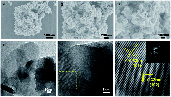 | ||
| Fig. 1 (a–c) SEM images, (d) TEM images, and (e and f) HRTEM images of CuSe nanosheets. The inset of (f) is the corresponding SAED pattern. | ||
To further explore the sample structure and composition, the XRD pattern (Fig. 2a) shows that the position of the diffraction peaks is in concordance with the standard PDF card of hexagonal CuSe with the klockmannite structure (PDF#34-0171). These evident and sharp diffraction lines at 26.4°, 28.1°, 31.0°, 41.6°, 45.3°, 46.0°, 49.9°, 53.9°, 54.8°, 56.5°, 70.3° and 74.3° could be well fitted with the (101), (102), (006), (106), (107), (110), (108), (201), (202), (116), (208) and (212) planes of the standard PDF card, respectively, and no signal of other components is detected, indicating that the hydrothermally synthesized CuSe has high crystallinity degree and purity.27 Besides, the Raman spectrum of the CuSe sample is shown in Fig. 2b. The distinct strong peak at about 257 cm−1 is attributed to the stretching vibration of the Se–Se bond (Se2 unit) in the hexagonal CuSe, which agrees with the previous report.27 As shown in the FTIR spectra, broadband was observed at 608 cm−1, which is attributed to the bending vibration of Cu–Se (Fig. S4†).28
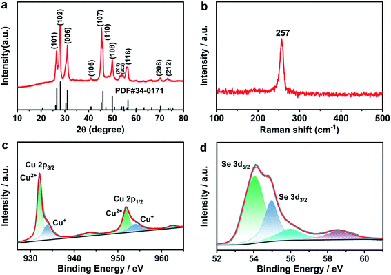 | ||
| Fig. 2 (a) XRD pattern, (b) Raman spectrum of CuSe, and high-resolution XPS spectra of (c) Cu 2p and (d) Se 3d for CuSe nanosheets. | ||
The oxidation states of CuSe nanosheets were further analyzed via X-ray photoemission spectroscopy (XPS). In the high-resolution XPS spectrum of Cu 2p (Fig. 2c), two characteristic peaks exist at the binding energies of 932.1 and 952.2 eV, which could be assigned to Cu2+ 2p3/2 and Cu2+ 2p1/2, respectively. These weak peaks at 933.8 and 951.9 eV belong to Cu+ 2p3/2 and Cu+ 2p1/2, and the peaks at 943.4 and 962.4 eV correspond to satellite peaks.29,30 Although two different valence states of Cu2+ and Cu+ exist in the CuSe nanosheets, the intensity of Cu2+ peaks is more than that of Cu+ peaks, demonstrating that the value state of Cu2+ is dominant in the CuSe nanosheets. Moreover, two evident peaks centered at the binding energies of 54.1 and 55.2 eV in Fig. 2d agree with Se 3d5/2 and Se 3d3/2 of Se2−, and the weak peaks at 56.2 and 58.5 eV could be ascribed to the oxidation peak of Se, which agrees with previous reports.31 In addition, the stoichiometric ratio of Cu and Se is close to 1![[thin space (1/6-em)]](https://www.rsc.org/images/entities/char_2009.gif) :
:![[thin space (1/6-em)]](https://www.rsc.org/images/entities/char_2009.gif) 1 through the analysis of the XPS full-spectrum (Fig. S5†), which is consistent with the results of EDX.
1 through the analysis of the XPS full-spectrum (Fig. S5†), which is consistent with the results of EDX.
3.2 Electrochemical performance
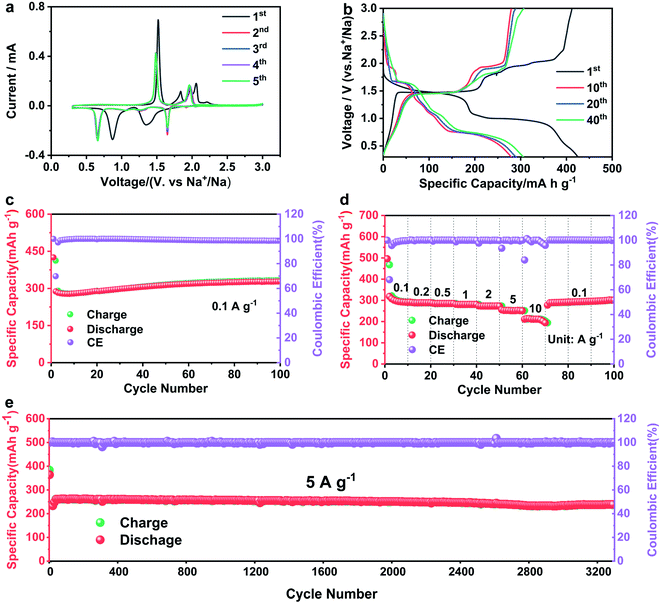
Discharge:
| CuSe + xNa+ + xe− → NaxCuSe | (1) |
| NaxCuSe + (2 − x)Na+ + (2 − x)e− → Na2Se + Cu | (2) |
Charge:
| Na2Se + Cu − 2e− → CuSe + 2Na+ | (3) |
Fig. 3b displays the charge–discharge curves of CuSe nanosheets at 0.1 A g−1. Two discharge platforms exist at 1.64 and 0.66 V in the discharge curve, and the charging platforms are at 1.48 and 1.95 V, which are consistent with the results of CV. The initial discharge capacity of the CuSe electrode is 425 mA h g−1 and initial coulombic efficiency is ∼96.7%, exceeding that of other copper selenide materials in previous studies (Table 1). The reason is the high conductivity and convenient reversible conversion of the CuSe nanosheets in the electrochemical process, indicating a high utilization of the electrolyte with the electrode materials.16,17 Although the discharge capacity at the 10th cycle is 279 mA h g−1, it increases to 307 mA h g−1 at the 40th cycle, showing an initial decrease and then an increased process as a whole. Consistently, Fig. 3c demonstrates the same tendency, and the specific capacity increased to 330 mA h g−1 after 70 cycles and remained constant above 70 cycles. This phenomenon may be caused by the activation of the electrode materials via the charge and discharge processes.17,22,36 Fig. 3d presents the rate capability of the CuSe electrode, in which its reversible specific capacity is preserved at 290, 285, 280, 273, and 250 mA h g−1 at current densities of 0.1, 0.5, 1, 2, and 5 A g−1, respectively. Furthermore, the specific capacity is maintained at 211 mA h g−1 under the high current density of 10 A g−1. Even when the current density returned to 0.1 A g−1, the specific capacity of 289 mA h g−1 was achieved. The long-term cycling performance of the CuSe electrode at a current density of 5 A g−1 is shown in Fig. 3e, in which the CuSe nanosheets have a reversible capacity of 261 mA h g−1 after the activation treatment of 10 cycles at 0.1 A g−1 and maintain a reversible capacity of 236 mA h g−1 after 3300 cycles with a capacity retention of 91.2%. These results demonstrate the prominent rate capability and cycle performance of CuSe nanosheets for SIBs.
| Cathode materials | ICE (%/A g−1) | Voltage window | Current density (mA g−1) | Capacity (mA h g−1) | References |
|---|---|---|---|---|---|
| CuSe nanosheets | 92.6/0.05 | 0.3–3.0 V | 100 | 361 | 17 |
| 5000 | 309 | ||||
| CuSe | 91.0/0.1 | 0.3–3.0 V | 100 | 340 | 16 |
10![[thin space (1/6-em)]](https://www.rsc.org/images/entities/char_2009.gif) 000 000 |
295 | ||||
| Cu2Se | 46.6/0.1 | 0.01–3.0 V | 100 | 193 | 37 |
| 2000 | 99 | ||||
| Cu2Se | 91.4/0.1 | 0.3–2.2 V | 100 | 264 | 34 |
| 1000 | 251 | ||||
| Cu2−xSe | _ | 0.3–2.5 V | 100 | 250 | 22 |
| 5000 | 241 | ||||
| Cu1.8Se/C | _ | 0.01–3.0 V | 100 | 301 | 26 |
| 5000 | 93.1 | ||||
| CuSe nanosheets | 96.7/0.1 | 0.3–3.0 V | 100 | 330 | Our work |
| 5000 | 261 |
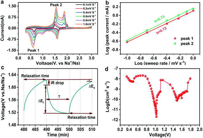
To reveal the reaction kinetics and superior performance of CuSe nanosheets, CV curves at different scan rates are recorded (Fig. 4a), in which the CV profiles display a similar curve shape, indicating excellent rate performance and reversible sodium storage capability of CuSe nanosheets. According to the existing reports,38 the peak current (i) of the pseudocapacitive contribution is proportional to the sweep rate (v), while the current associated with the diffusion control program is proportional to the quadrat root of the sweep rate. Therefore, the qualitative deduction for the charge storage mechanism can be obtained using the following formula:39
| i = avb | (4) |
In addition, galvanostatic intermittent titration technique (GITT) tests were performed to calculate the diffusion rate of Na+ ions. The CuSe nanosheets for SIBs were discharged for 600 s (τ) at a constant current of 10 mA g−1, followed by an open circuit standing of 600 s. Na+ ion diffusion coefficients (DNa) can be obtained using the following formula:
 | (5) |
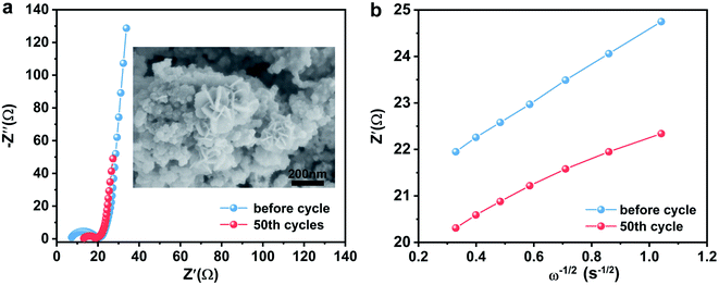
In order to further study the reaction kinetics during charge and discharge processes, the EIS spectrum of the CuSe electrode were obtained (Fig. 5a). As presented in Table 1, the CuSe electrode showed larger charge transfer resistance (Rct) before the electrochemical test, whereas the resistance decreased from 13.7 Ω to 6.2 Ω after 50 cycles, indicating the activation and faster charge-transfer rate of the CuSe electrode. Furthermore, the diffusion coefficient (D, cm2 s−1) of Na+ in the electrode is calculated using the following formula:35
 | (6) |
![[thin space (1/6-em)]](https://www.rsc.org/images/entities/char_2009.gif) 500 C mol−1); C is the concentration of Na+ in the positive electrode materials; and σ is the Warburg coefficient. In the low-frequency region, it is related to the impedance function Z′and the angular frequency ω = 2πf. This can be concluded from the following formula:
500 C mol−1); C is the concentration of Na+ in the positive electrode materials; and σ is the Warburg coefficient. In the low-frequency region, it is related to the impedance function Z′and the angular frequency ω = 2πf. This can be concluded from the following formula:| Z′ = Re + Rct + σω−1/2 | (7) |
The relational curves between Z′ and ω−1/2 in the low-frequency region are shown in Fig. 5b. The results exhibit that the diffusion coefficients of Na+ in the CuSe electrode increase from 5.379 × 10⁻¹¹ cm2 s−1 to 1.214 × 10⁻¹⁰ cm2 s−1 after 50 cycles (Table 2), which agrees with the GITT conclusions. Moreover, the morphology of the CuSe nanosheets is well maintained after 50 cycles (inset in Fig. 5a), demonstrating the stable structure of CuSe nanosheets during the electrochemical process.
| Before cycling | After 50 cycles | |
|---|---|---|
| Rs (Ω) | 7.2 | 13.14 |
| Rct (Ω) | 13.7 | 6.2 |
| D (cm2 s−1) | 5.379 × 10⁻¹¹ | 1.214 × 10⁻¹⁰ |
![[thin space (1/6-em)]](https://www.rsc.org/images/entities/char_2009.gif) :
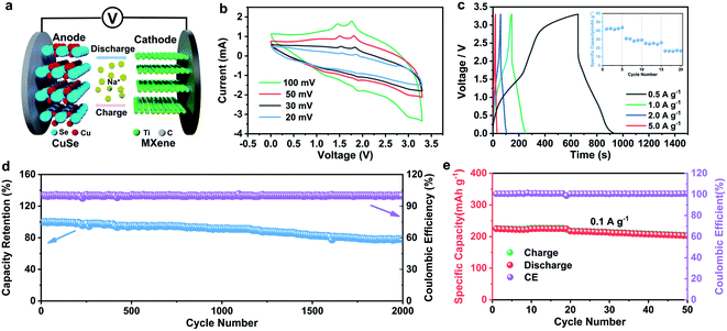
:![[thin space (1/6-em)]](https://www.rsc.org/images/entities/char_2009.gif) 1.43,44 In electrochemical tests, the CV measurements of CuSe//Ti3C2Tx MXene SHIC devices at different scan rates were carried out in the operating voltage window of 0–3.3 V (Fig. 6b). The CV profiles have similar curve shapes even as the scan rates increase, indicating excellent reversibility and rate performance. As depicted in Fig. 6c, the CuSe//Ti3C2Tx MXene SHIC device possesses specific capacities of 42.7, 31.1, 25.7, and 17.3 mA h g−1 at current densities of 0.5, 1.0, 2.0, and 5.0 A g−1, respectively. Furthermore, the energy density and power density of the SHIC are 63.4 W h kg−1 (at 459.1 W kg−1), 47.8 W h kg−1 (at 1009.0 W kg−1), 40.2 W h kg−1 (at 1828.4 W kg−1), and 29.7 W h kg−1 (at 3625.5 W kg−1), exhibiting comparable sodium-storage performance.26,45,46 In addition, at the current density of 2 A g−1, the capacitance retention rate is 77.7% after 2000 cycles (Fig. 6d), indicating that it has good cycle stability.
1.43,44 In electrochemical tests, the CV measurements of CuSe//Ti3C2Tx MXene SHIC devices at different scan rates were carried out in the operating voltage window of 0–3.3 V (Fig. 6b). The CV profiles have similar curve shapes even as the scan rates increase, indicating excellent reversibility and rate performance. As depicted in Fig. 6c, the CuSe//Ti3C2Tx MXene SHIC device possesses specific capacities of 42.7, 31.1, 25.7, and 17.3 mA h g−1 at current densities of 0.5, 1.0, 2.0, and 5.0 A g−1, respectively. Furthermore, the energy density and power density of the SHIC are 63.4 W h kg−1 (at 459.1 W kg−1), 47.8 W h kg−1 (at 1009.0 W kg−1), 40.2 W h kg−1 (at 1828.4 W kg−1), and 29.7 W h kg−1 (at 3625.5 W kg−1), exhibiting comparable sodium-storage performance.26,45,46 In addition, at the current density of 2 A g−1, the capacitance retention rate is 77.7% after 2000 cycles (Fig. 6d), indicating that it has good cycle stability.
4. Conclusions
In summary, two-dimensional phase-pure CuSe nanosheets were successfully synthesized by a facile and simple hydrothermal reaction using inexpensive and easily available reagents. Benefiting from the high conductivity and morphological characteristics of two-dimensional CuSe nanosheets with a large effective surface area, abundant electrochemically active sites and a convenient ion transportation path, the CuSe electrode for SIBs exhibited high-rate capability and long-term stability. Furthermore, CuSe nanosheets for sodium-ion hybrid capacitors also resulted in the desired energy density (63.4 W h kg−1 at 459.1 W kg−1) and relatively long cycle life (77.7% capacitance retention with 2000 cycles at 2 A g−1).Conflicts of interest
There are no conflicts to declare.Acknowledgements
This work was supported by the National Natural Science Foundation of China (No. U1904173, 61874093 and 61574122), Zhongyuan Thousand Talents Plan-Science & Technology Innovation Leading Talents Project (No. 194200510009), Key Research Projects of Henan Provincial Department of Education (No. 19A150043), Natural Science Foundation of Henan Province (No. 202300410330), Nanhu Scholars Program for Young Scholars of Xinyang Normal University, as well as Xinyang Normal University Analysis & Testing Center.References
- M. Huang, X. Wang, X. Liu and L. Mai, Adv. Mater., 2022, 34, 2105611 CrossRef CAS PubMed.
- K. Cao, H. Liu, Y. Jia, Z. Zhang, Y. Jiang, X. Liu, K.-J. Huang and L. Jiao, Adv. Mater. Technol., 2020, 5, 2000199 CrossRef CAS.
- Z. Zhang, S. Wu, C. Yang, L. Zheng, D. Xu, R. Zha, L. Tang, K. Cao, X.-g. Wang and Z. Zhou, Angew. Chem., Int. Ed., 2019, 58, 17782–17787 CrossRef CAS PubMed.
- S. Liu, W. Zheng, W. Xie, H. Cui, Y. Li, C. Zhang, Z. Ji, F. Liu, R. Chen, H. Sun and J. Xu, Carbon, 2022, 192, 162–169 CrossRef CAS.
- K. Cao, R. Zheng, S. Wang, J. Shu, X. Liu, H. Liu, K.-J. Huang, Q.-S. Jing and L. Jiao, Adv. Funct. Mater., 2020, 30, 2007712 CrossRef CAS.
- J. Xu, Q. Liu, Z. Dong, L. Wang, X. Xie, Y. Jiang, Z. Wei, Y. Gao, Y. Zhang and K. Huang, ACS Appl. Mater. Interfaces, 2021, 13, 54974–54980 CrossRef CAS PubMed.
- H. Liu, Y. He, H. Zhang, K. Cao, S. Wang, Y. Jiang, Q.-S. Jing and L. Jiao, Chem. Eng. J., 2021, 425, 130548 CrossRef CAS.
- M. Ou, S. Sun, Y. Liu, Y. Xu, C. Chen, P. Hu, C. Fang, Q. Li and J. Han, RSC Adv., 2021, 11, 22297–22304 RSC.
- H. Liu, Y. He, K. Cao, S. Wang, Y. Jiang, X. Liu, K.-J. Huang, Q.-S. Jing and L. Jiao, Small, 2021, 17, 2008133 CrossRef CAS PubMed.
- X. Xie, K. Huang, X. Wu, N. Wu, Y. Xu, S. Zhang and C. Zhang, Carbon, 2020, 169, 1–8 CrossRef CAS.
- X. Li, D. Pan, J. Deng, R. Wang, J. Huang, W. Lü, T. Yao, X. Wang, Y. Zhang, L. Xu, Y. Bai, P. Xu and B. Song, J. Mater. Chem. A, 2021, 9, 25954–25963 RSC.
- M. Sajjad, F. Cheng and W. Lu, RSC Adv., 2021, 11, 25450–25460 RSC.
- J. Huang, Y. Cao, M. Cao and J. Zhong, RSC Adv., 2021, 11, 34079–34085 RSC.
- B. Wang, X. Miao, H. Dong, X. Ma, J. Wu, Y. Cheng, H. Geng and C. C. Li, J. Mater. Chem. A, 2021, 9, 14582–14592 RSC.
- Y. Zhu, H. Li, Y. Wu, L. Yang, Y. Sun, G. Chen, Y. Liu, Z. Wu, C. Zhang and X. Guo, RSC Adv., 2021, 11, 28488–28495 RSC.
- H. Lin, M. Li, X. Yang, D. Yu, Y. Zeng, C. Wang, G. Chen and F. Du, Adv. Energy Mater., 2019, 9, 1900323 CrossRef.
- D. Yu, X. Wei, D. Zhao, S. Gao, G. Zhao, H. Zhang, Z. Li, M. Yu and Y. Sun, Electrochim. Acta, 2022, 404, 139703 CrossRef CAS.
- H. Wang, X. Xu and A. Neville, RSC Adv., 2021, 11, 26273–26283 RSC.
- J. Zong, F. Wang, C. Nie, M. Zhao and S. Yang, J. Mater. Chem. A, 2022, 10, 10651–10661 RSC.
- J. Zhang, X. Zhang, C. Xu, H. Yan, Y. Liu, J. Xu, H. Yu, L. Zhang and J. Shu, Adv. Energy Mater., 2022, 12, 2103998 CrossRef CAS.
- Z. Sun, Z. Gu, W. Shi, Z. Sun, S. Gan, L. Xu, H. Liang, Y. Ma, D. Qu, L. Zhong, D. Han, X.-L. Wu and L. Niu, J. Mater. Chem. A, 2022, 10, 2113–2121 RSC.
- Y. Li, X. Sun, Z. Cheng, X. Xu, J. Pan, X. Yang, F. Tian, Y. Li, J. Yang and Y. Qian, Energy Storage Mater., 2019, 22, 275–283 CrossRef.
- P. Xu, G. Wang, C. Miao, K. Cheng, K. Ye, K. Zhu, J. Yan, D. Cao and X. Zhang, Appl. Surf. Sci., 2019, 463, 82–90 CrossRef CAS.
- L. Li, Y. Zhao, C. Shi, W. Zeng, B. Liao, M. Zhang and X. Tao, RSC Adv., 2021, 11, 25955–25960 RSC.
- J. L. Yue, Q. Sun and Z. W. Fu, Chem. Commun., 2013, 49, 5868–5870 RSC.
- X. Shi, J. Yu, Q. Liu, L. Shao, J. Cai and Z. Sun, Sustainable Mater. Technol., 2021, 28, e00275 CrossRef CAS.
- Y. Zhang, Y. Zhu, Z. Wang, H. Peng, X. Yang, Y. Cao, C. Du, X. Ma and C. Cao, Adv. Funct. Mater., 2021, 31, 2104730 CrossRef CAS.
- Y. E. Firat and A. Peksoz, J. Alloys Compd., 2017, 727, 177–184 CrossRef CAS.
- L. Tan, N. Li, S. Chen and Z.-Q. Liu, J. Mater. Chem. A, 2016, 4, 12273–12280 RSC.
- Z. Yang, H. Li, J. Yang, S. Feng, X. Liu, J. Zhao, W. Qu, P. Li, Y. Feng, P.-H. Lee and K. Shih, Adv. Funct. Mater., 2019, 29, 1807191 CrossRef.
- J. Masud, W. P. R. Liyanage, X. Cao, A. Saxena and M. Nath, ACS Appl. Energy Mater., 2018, 1, 4075–4083 CrossRef CAS.
- L. Yang, W. Hong, Y. Tian, G. Zou, H. Hou, W. Sun and X. Ji, Chem. Eng. J., 2020, 385, 123838 CrossRef CAS.
- J. Zhu, Q. He, Y. Liu, J. Key, S. Nie, M. Wu and P. K. Shen, J. Mater. Chem. A, 2019, 7, 16999–17007 RSC.
- L. Shao, S. Wang, J. Qi, Z. Sun, X. Shi, Y. Shi and X. Lu, Mater. Today Phys., 2021, 19, 100422 CrossRef CAS.
- H. Li, J. Jiang, J. Huang, Y. Wang, Y. Peng, Y. Zhang, B.-J. Hwang and J. Zhao, ACS Appl. Mater. Interfaces, 2018, 10, 13491–13498 CrossRef CAS PubMed.
- H. Park, J. Kwon, H. Choi, D. Shin, T. Song and X. W. D. Lou, ACS Nano, 2018, 12, 2827–2837 CrossRef CAS PubMed.
- L. Hu, C. Shang, E. M. Akinoglu, X. Wang and G. Zhou, Nanomaterials, 2020, 10, 302 CrossRef CAS PubMed.
- J. Liu, J. Wang, C. Xu, H. Jiang, C. Li, L. Zhang, J. Lin and Z. X. Shen, Adv. Sci., 2018, 5, 1700322 CrossRef.
- Y. Shao, M. F. El-Kady, J. Sun, Y. Li, Q. Zhang, M. Zhu, H. Wang, B. Dunn and R. B. Kaner, Chem. Rev., 2018, 118, 9233–9280 CrossRef CAS PubMed.
- N. H. Bashian, S. Zhou, M. Zuba, A. M. Ganose, J. W. Stiles, A. Ee, D. S. Ashby, D. O. Scanlon, L. F. J. Piper, B. Dunn and B. C. Melot, ACS Energy Lett., 2018, 3, 2513–2519 CrossRef CAS.
- Z. Li, H. Zhao, Z. Du, L. Zhao, J. Wang and Z. Zhang, J. Power Sources, 2020, 465, 228253 CrossRef CAS.
- H. He, H. Zhang, D. Huang, W. Kuang, X. Li, J. Hao, Z. Guo and C. Zhang, Adv. Mater., 2022, 34, e2200397 CrossRef.
- T. Zhang, R. Wang, B. He, J. Jin, Y. Gong and H. Wang, Electrochem. Commun., 2021, 129, 107090 CrossRef CAS.
- Y.-L. Wang, L.-Q. Fan, S.-J. Sun, J.-J. Chen, Z.-X. Wu, T.-T. Zhu, Y.-F. Huang and J.-H. Wu, Chem. Eng. J., 2022, 428, 131993 CrossRef CAS.
- M. Liu, J. Niu, Z. Zhang, M. Dou, Z. Li and F. Wang, J. Power Sources, 2019, 414, 68–75 CrossRef CAS.
- A. M. Zardkhoshoui and S. S. H. Davarani, Chem. Eng. J., 2020, 402, 126241 CrossRef CAS.
Footnotes |
| † Electronic supplementary information (ESI) available. See https://doi.org/10.1039/d2ra03206f |
| ‡ These authors contributed equally to this work. |
| This journal is © The Royal Society of Chemistry 2022 |


