 Open Access Article
Creative Commons Attribution 3.0 Unported Licence
Surface plasmon-driven photoelectrochemical water splitting of a Ag/TiO2 nanoplate photoanode†
Piangjai Peerakiatkhajohn a,
Jung-Ho Yun
 b,
Teera Butburee
 c,
Waraporn Nisspad and
Supphasin Thaweesak
 *e
*e
aFaculty of Environment and Resource Studies, Mahidol University, Nakhon Pathom 73170, Thailand. E-mail: piangjai.pee@mahidol.ac.th
bNanomaterials Centre, School of Chemical Engineering and Australian Institute for Bioengineering and Nanotechnology (AIBN), The University of Queensland, St Lucia, QLD 4123, Australia. E-mail: j.yun1@uq.edu.au
cNational Nanotechnology Center, National Science and Technology Development Agency, 111 Thailand Science Park, Pathum Thani 12120, Thailand. E-mail: teera.but@nanotec.or.th
dDivision of Science and Technology, Faculty of Science and Technology, Phetchaburi Rajabhat University, Phetchaburi 76000, Thailand. E-mail: waraporn.bun@mail.pbru.ac.th
eDepartment of Chemical Engineering, Faculty of Engineering, Burapha University, Chon Buri 20131, Thailand. E-mail: supphasin@eng.buu.ac.th
First published on 20th January 2022
Abstract
A silver/titanium dioxide nanoplate (Ag/TiO2 NP) photoelectrode was designed and fabricated from vertically aligned TiO2 nanoplates (NP) decorated with silver nanoparticles (NPs) through a simple hydrothermal synthesis and electrodeposition route. The electrodeposition times of Ag NPs on the TiO2 NP were crucial for surface plasmon-driven photoelectrochemical (PEC) water splitting performance. The Ag/TiO2 NP at the optimal deposition time of 5 min with a Ag element content of 0.53 wt% demonstrated a remarkably high photocurrent density of 0.35 mA cm−2 at 1.23 V vs. RHE under AM 1.5G illumination, which was 5 fold higher than that of the pristine TiO2 NP. It was clear that the enhanced light absorption properties and PEC performance for Ag/TiO2 NP could be effectively adjusted by simply controlling the loading amounts of metallic Ag NPs (average size of 10–30 nm) at different electrodeposition times. The superior PEC performance of the Ag/TiO2 NP photoanode was attributed to the synergistic effects of the plasmonic Ag NPs and the TiO2 nanoplate. Interestingly, the plasmonic effect of Ag NPs not only increased the visible-light response (λmax = 570 nm) of TiO2 but also provided hot electrons to promote photocurrent generation and suppress charge recombination. Importantly, this study offers a potentially efficient strategy for the design and fabrication of a new type of TiO2 hybrid nanostructure with a plasmonic enhancement for PEC water splitting.
Introduction
Photoelectrochemical water splitting is a promising approach to produce renewable hydrogen fuel from abundant solar energy. Typically, a photoelectrode should provide strong optical absorption, good stability, effective carrier separation, and less recombination of electron–hole pairs in order to meet the requirements of an efficient PEC system.1–3 Since its inception in 1972 by Fujishima and Honda4 many researchers have focused on TiO2 due to its relatively high reactivity, chemical stability, low cost, and environmentally friendly features.5–7 Nevertheless, TiO2 has several drawbacks such as its relatively wide band gap (∼3.2 eV for anatase), making it active only in the ultraviolet (UV) light region, which constitutes only about 5–7% of the solar spectrum.8–10 In addition, TiO2 has a high recombination rate of photoexcited electron–hole pairs, leading to a lower PEC performance.5 Thus, improving visible-light response and suppressing charge recombination in TiO2 are great challenges for efficient hydrogen production via PEC water splitting.3,11 Many strategies have been demonstrated to overcome these drawbacks, such as metal and non-metal doping,12–15 coupling with other semiconductors,16–19 and noble metal deposition.20–22In particular, engineering of nanostructures such as one-dimensional (1D),23–25 two-dimensional (2D),26–28 and three-dimensional (3D)29–31 structures is an approach to promote effective charge separation; especially, the 2D TiO2 structure is an ideal building block for further nanoengineering of heterostructure materials for enhanced PEC water splitting application. Additionally, the noble metal deposition has proved to be an effective technique to extend the photoresponse of TiO2 to the visible light range and suppress the recombination of the photogenerated electrons–holes. Among the noble metals, silver (Ag) is an attractive metal due to its strong surface plasmon resonance (SPR) effect along with extraordinary physicochemical properties and less expensive compared to gold, palladium, and platinum.32,33 Various studies of Ag–TiO2 composites for efficient PEC water splitting have been demonstrated;34–39 for instance, Peng et al. successfully decorated the plasmonic Ag NPs on TiO2 nanowires for the enhancement of PEC water splitting performance,32 and Hou et al. reported TiO2 nanotube arrays coupled with Ag NPs, exhibiting impressive PEC water splitting activities.40 A comparative table summary of recent studies for Ag/TiO2 photoanodes is shown in ESI Table S1.† However, there are still some concerns, such as low PEC performance, complicated synthesis procedures, and complex structural fabrication.
In this work, an environmentally benign, economical, and facile technique to synthesize Ag-deposited TiO2 nanoplates (Ag/TiO2 NP) as a photoanode was reported, by the combination of a hydrothermal method and an electrodeposition technique. The Ag NP deposition can be achieved by several methods such as electrodeposition,34,37,41 photodeposition,35,36,42 and chemical reduction.43–45 Among various techniques, electrodeposition has arisen as a promising technique for fabricating photoelectrodes due to its relative simplicity, low cost, and good dispersion, and improves interfacial deposition between the deposited layer and supporting electrode substrate. Furthermore, the most attractive feature of electrodeposition is its feasibility in terms of particle coverage density and properties related to the catalytic activity can be easily controlled by tuning the electrolyte composition, deposition time, and applied potential when compared to other Ag NP fabrication techniques.37,46
The Ag/TiO2 NP photoanodes were also characterized using various spectroscopic, microscopic, crystallographic, and photoelectrochemical techniques to determine the optical, physico-chemical, and electrochemical properties. Therefore, the transfer-enhancement synergistic mechanism is proposed to understand the role of the plasmonic effect of Ag NPs.
Results and discussion
Fig. 1(a)–(d) are the SEM images of the structural morphology from the top view and Fig. 1(e) and (f) are the cross-sectional view of the as-prepared TiO2 and Ag/TiO2 photoanodes. Fig. 1(a) shows the top view SEM image of the TiO2 layer which confirms the formation of dense vertically aligned 2D nanoplates with exposed {101} and {001} facets.47,48 According to our previous study,47 it was found that protons (H+) and fluoride ions (F−) play a synergistic role in controlling the morphology and crystal phases of TiO2. The ion of F− changes the crystal phases of TiO2 from rutile to anatase with low-index facets, while increasing amount of H+ promotes the growth of the {001} facet.49 The percentage of the {001} facet synthesized in this work was quantified by Raman spectroscopy, which was 9.97% (ESI Fig. S1†).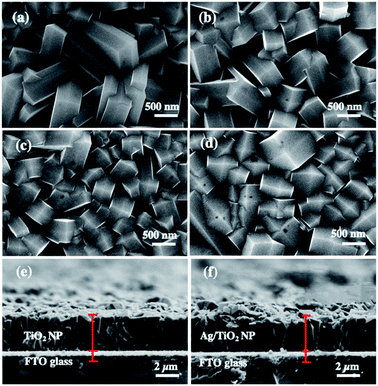 | ||
| Fig. 1 FE-SEM images of (a) TiO2 NP, (b) 1m-Ag/TiO2, (c) 3m-Ag/TiO2, and (d) 5m-Ag/TiO2 NP photoanodes, and cross-section SEM images of (e) TiO2 NP and (f) 5m-Ag/TiO2 NP photoanodes. | ||
Fig. 1(b)–(d) show the circular patches of the Ag deposited onto the TiO2 NP. Cross-sectional images in Fig. 1(e) and (f) display the film thicknesses of TiO2 and 5m-Ag/TiO2 NP photoanodes, which are approximately 3 μm.
The TiO2 and Ag/TiO2 photoanodes were analyzed by transmission electron microscopy (TEM) and high-resolution transmission electron microscopy (HRTEM). The TEM images of TiO2 and 5m-Ag/TiO2 NP photoanodes as shown in Fig. 2(a) and (b) reveal the nanoplate structure of TiO2 and distribution of Ag NPs on the TiO2 structure with the diameters of about 10 to 30 nm, respectively. Fig. 2(c) displays the TEM image of spherical shape Ag NPs with an average size range of 10–30 nm for the electrodeposition process. Furthermore, Fig. 2(d) presents the HRTEM image of the Ag/TiO2 NP photoanode which confirms the coexistence of TiO2 and Ag NPs with a clear lattice fringe spacing of 0.35 nm and 0.24 nm, in accordance with the d-spacings of (101) of anatase TiO2 and (111) of Ag NPs, respectively.41,50 Additionally, Fig. 2(e) shows a sharp selected area electron diffraction (SAED) pattern, further confirming that the Ag/TiO2 NP is a single crystalline anatase structure with Ag NPs (111). Fig. 2(f) illustrates the XRD patterns of the synthesized TiO2 NP and Ag/TiO2 photoanodes. TiO2 NPs exhibit the major peaks at 2θ values of 25.28°, 37.8°, 38.58°, 48.05°, 55.06°, 62.12°, and 70.03°, which correspond to the characteristic peaks of anatase at (101), (004), (112), (200), (211), (213) and (220), respectively (JCPDS no. 21-1272). The Ag/TiO2 NP photoanode exhibits the peaks of Ag nanoparticles deposited on the TiO2 NP surface at 2θ of 38.12°, 64.42°, and 77.47°, corresponding to (111), (220) and (311) planes of Ag, respectively (JCPDS no. 04-0783). This result can indicate the existence of crystalline Ag nanoparticles in the nanocomposites of Ag/TiO2 NP.
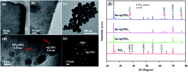 | ||
| Fig. 2 TEM images of (a) TiO2 NP, (b) Ag/TiO2 NP, and (c) Ag NPs, (d) HRTEM image of Ag/TiO2, (e) SAED pattern of Ag/TiO2, and (f) XRD patterns of the photoanode. | ||
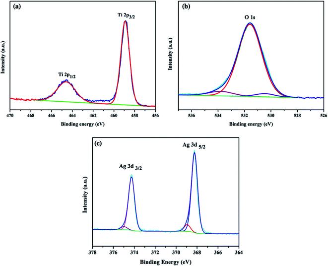
The elemental composition and chemical state of the Ag/TiO2 photoanode were investigated by high-resolution XPS spectra as shown in Fig. 3. Fig. 3(a) illustrates the XPS spectra of Ti 2p; there are two major peaks with binding energies at 464.9 eV and 459.1 eV, corresponding to Ti 2p3/2 and Ti 2p1/2, respectively. Fig. 3(b) exhibits the O 1s region, and the peak at 530.0 eV can be assigned to oxygen atoms in the TiO2 lattice.51 Fig. 3(c) shows two peaks at binding energies of 367.9 eV (Ag 3d5/2) and 373.9 eV (Ag 3d3/2), which were close to those expected for metallic Ag0 (368.0 eV and 374.0 eV).9,35,52 Thus, Ag NPs on TiO2 NP were mainly in the metallic state, which is consistent with the HRTEM and XRD results.
In addition, the existence of Ag NPs on TiO2 was confirmed by energy-dispersive X-ray spectroscopy (EDS) as shown in Fig. 4(a)–(d). The EDS results reveal that the TiO2 NP contained peaks of Ti and O elements, while Ag/TiO2 NP contained peaks of Ti and O, and an additional peak of Ag at ∼2.9 eV, indicating that the Ag NPs in various Ag/TiO2 NP samples are mainly in the metallic form. In addition, elemental mapping depicts the uniform distribution of Ti, O and Ag atoms in the Ag/TiO2 NP. The weight percentages of Ag element in Ag/TiO2 NP of different electrodeposition times at 1, 3, and 5 min were 0.12, 0.34, and 0.53 wt%, respectively. The EDS results indicate that the amount of Ag nanoparticles increases with the extension of electrodeposition time which is in good agreement with the XRD results.
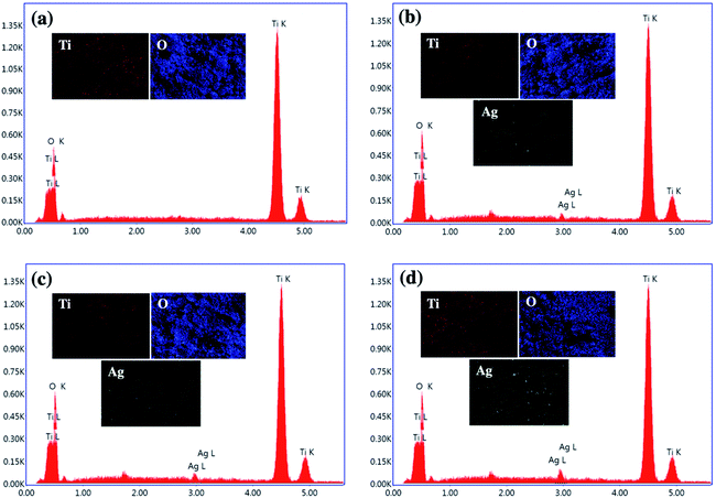 | ||
| Fig. 4 The EDS spectra and elemental mapping images of (a) TiO2 NP, (b) 1m-Ag/TiO2, (c) 3m-Ag/TiO2, and (d) 5m-Ag/TiO2 NP photoanodes. | ||
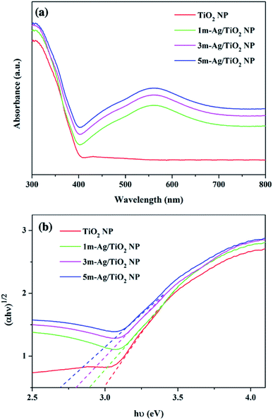
UV-Vis absorption spectra of the pristine TiO2 and Ag/TiO2 NP photoanodes are shown in Fig. 5(a). The pristine TiO2 and Ag/TiO2 NP photoanodes display similar absorption intensity in the UV region. The absorption edge around 380 nm of the pristine TiO2 NPs is ascribed to the band-to-band transition of anatase TiO2.53 The absorption spectrum of Ag/TiO2 NP photoanodes shows a broad absorption band in the range of 400–700 nm with the maximum absorption at 570 nm compared to that of the bare TiO2.
The peak broadening is observed towards a higher wavelength which could be attributed to the SPR effect which was induced by the spatial confinement of electrons in Ag0 particles on the surface of TiO2 NP and the high dispersion of Ag on the TiO2.54,55 Furthermore, the Tauc equation was applied to calculate the band gap energy (Eg) as follows:
| (αhν)n = A(hν − Eg) |
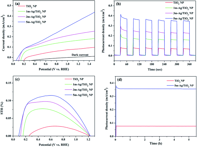
The linear sweep voltammetric (I–V) curves for the pristine TiO2 and the Ag/TiO2 NP photoanodes were measured in a potential range from 0 to 1.5 V vs. RHE in 0.5 M Na2SO4 electrolyte under simulated AM 1.5G illumination as shown in Fig. 6(a). The photo generated potential of Ag/TiO2 photoanodes immediately shifts to a more negative value due to the sudden generation of photogenerated electron–hole pairs under light illumination. Obviously, the shift of the onset potential toward the lower bias when more Ag NPs were deposited is due to the lower band bending and the better charge transport.57,58 The photocurrent density of all Ag/TiO2 NP photoelectrodes is higher than that of TiO2 NP and increases significantly at all potentials. This could be attributed to a better electron–hole separation and SPR effect of Ag NPs, which is consistent with the light absorption spectra and the narrowing energy bandgap. Fig. 6(b) presents the transient photocurrent response of TiO2 and Ag/TiO2 NP photoanodes with chopping light at 1.23 V (vs. RHE) under simulated AM 1.5G illumination. The pristine TiO2 NP photoanode exhibits a photocurrent density of 0.07 mA cm−2, comparable to other reported PEC systems by the TiO2 photoanode.59,60 Upon deposition of Ag NPs at different electrodeposition times, the photocurrent density of 1m-Ag/TiO2, 3m-Ag/TiO2, and 5m-Ag/TiO2 NP photoanodes is drastically increased to 0.15, 0.22, and 0.35 mA cm−2, respectively. Interestingly, the photocurrent density of the 5m-Ag/TiO2 NP photoanode is ∼5 times higher than that of the pristine TiO2 NP photoanode. For photoanodes with longer Ag NP deposition time than 5m-Ag/TiO2 NP photoanodes, 7m-Ag/TiO2 NP and 10m-Ag/TiO2 NP, the photocurrent density decreases slightly to 0.30 and 0.27 mA cm−2, respectively with a positive shift of onset potential as shown in ESI Fig. S2.† The excess amount of Ag NPs on the TiO2 NP photoanode function as recombination sites, thus decreasing the photoelectrochemical activity. This phenomenon is also reported by other studies.37,39 Fig. 6(c) shows the calculated STH efficiencies of these photoelectrodes based on the I–V characteristics. The 5m-Ag/TiO2 NP photoanode exhibits the maximum STH value of approximately 0.12%. Additionally, the 5m-Ag/TiO2 NP photoelectrode shows extraordinarily high stability for a stable photocurrent for at least 5 hours, as shown in Fig. 6(d). This result indicated that surface modification of TiO2 with an economical noble metal (Ag) is an effective strategy to improve the PEC performance which is comparable to other studies (ESI Table S1†).
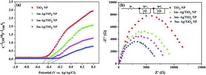
To investigate the role of deposited Ag NPs in the enhancement of photoelectrochemical performance and electronic properties of the TiO2 photoelectrode, the Mott–Schottky (MS) curves were investigated as shown in Fig. 7(a). The slopes of the TiO2 and all Ag/TiO2 photoanodes are all positive, indicating the n-type behaviour.58,61 In addition, the charge carrier densities (Nd) can be calculated from the slopes of MS plots using the equation as follows.62
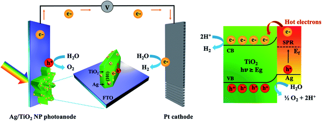
The results of characterization and PEC measurements demonstrated that the optical property, electronic property, and photocurrent density of Ag/TiO2 NP photoanodes significantly depend on the electrodeposition time of Ag NP decoration. The light absorption characteristic increased gradually with the increase in deposition time, leading to the enhancement of photocurrent density. Furthermore, it could be seen that all modified TiO2 NP photoanodes with Ag NPs revealed higher photocurrent density than the pristine TiO2. Among Ag/TiO2 NP photoanodes, the 5m-Ag/TiO2 photoanode presented the highest photocurrent density of 0.35 mA cm−2 at 1.23 V vs. RHE under AM 1.5G illumination, which is ∼5 times higher compared to that of the pristine TiO2 NP. A proposed mechanism of the Ag/TiO2 NP photoanode for the enhanced PEC performance can be seen in Fig. 8. A vertically oriented TiO2 NP with exposed active {101}–{001} facet pairs and an interconnected framework provides an excellent architectural arrangement for facilitating charge carrier transport; for instance, Butburee et al. reported that the co-exposure of {101} and {010} facets could promote efficient charge separation for reduction reactions in PEC water splitting, due to their different electron affinities.66 There are several experiments showing that photogenerated electrons are likely to move and aggregate on the {101} facet, and vice versa, holes are likely to move and aggregate on the {001} facet.67 Besides, TiO2 NP arrays created more reaction sites between the photoanode and the electrolyte.6,26 Thus, using TiO2 nanostructures with good crystallinity could provide a better transfer pathway for photogenerated electrons, and assisted faster electron transport as mentioned by other studies.68–70 Furthermore, the deposition of Ag NPs onto TiO2 NP surfaces promoted significantly improved light harvesting in the broad wavelength region due to surface plasmon resonance (SPR) and effective charge transfer.42,71,72 In addition, HRTEM and elemental mapping exhibited that the Ag NPs with relatively uniform particle sizes distribute throughout the TiO2 NP. The Ag NPs play an important role for inducing more photogenerated charge carriers as an electron reservoir to suppress the charge recombination at the TiO2 photoanode.13 Under UV light illumination, the electron–hole pairs are immediately generated in TiO2, and the electrons in the conduction band can be directly transferred to the underneath FTO substrate for H2 generation at the Pt counter electrode. Under visible light irradiation, the incident light coincides with the localized surface plasmon resonances (LSPR) of the plasmonic Ag NPs and consequently the hot electrons near the Fermi level (EF) are generated and excited to the higher-energy states. These hot electrons with sufficient energy overcome the Schottky barrier formed at the interface between Ag and TiO2 which can significantly retard the recombination of electron–hole pairs,54,73 move to the conduction band of TiO2, and finally transfer to the Pt counter electrode via an external circuit for hydrogen production. And the photogenerated holes can participate in the water oxidation process or O2 evolution. Thus, the redox reaction and photocurrent density are improved. It is in good agreement with the study by Sang et al., which described the enhanced PEC performance using Ag NPs and reduced graphene oxide (rGO) co-decorated hierarchical TiO2 nanoring/nanotube arrays that was mainly attributed to the effective utilization of hot electrons generated from surface plasmon resonance and effective photogenerated electron transfer of Ag NPs.54
Experimental section
All chemicals were of analytical grade, and used without further purification. Titanium tetra n-butoxide (Ti(OC4H9)4), ammonium hexafluorotitanate ((NH4)2TiF6), and hydrochloric acid (HCl) were purchased from Sigma-Aldrich. Conductive fluorine-doped tin oxide (FTO, thickness around 2.3 mm, 15 Ω sq−1) glasses were used for all working electrodes (OPV Tech). All water used in the experiments was Milli-Q water (18.2 MΩ). A controlled DC power source (Agilent Technologies, Model E 3949A) supplied the required constant potential.Preparation of the TiO2 nanoplate photoanode (TiO2 NP)
The TiO2 nanoplate-like photoanode was synthesized using Ti(OC4H9)4 and (NH4)2TiF6 as precursors and HCl as a structure-directing agent in a hydrothermal reactor. The precursor solution for hydrothermal treatment was prepared by mixing 22 mL of 37% HCl in 24 mL of Milli-Q water under constant stirring at room temperature for 5 min. Then, 2 mL of Ti(OC4H9)4 was added into the above solution under constant stirring at room temperature for 5 min. Subsequently, 0.4 g of (NH4)2TiF6 was added into the mixture with continual stirring for 15 min to obtain a clear solution with pH = 5. Afterward, the as-prepared precursor was then transferred into a 50 mL Teflon-lined stainless-steel autoclave. The FTO glass substrate was cleaned by ultrasonic treatment using acetone, ethanol, and isopropanol (each for 15 min), followed by drying in a nitrogen stream and then immersed in an autoclave with the FTO side leaned against the wall. Then, the autoclave was sealed and hydrothermally treated at 170 °C for 12 h. After the hydrothermal process, the FTO substrate was brought out, rinsed with Milli-Q water, and dried in a nitrogen stream. Finally, the as-prepared TiO2 photoanode was subsequently annealed in air at 500 °C for 30 min with a ramping rate of 2 °C min−1.Preparation of Ag deposited TiO2 nanoplate photoanodes (Ag/TiO2 NP)
Ag NPs were synthesized by a modified Tollens' method and our previous study.46,74 In brief, Tollens' reagent was prepared by adding 5 mL of 0.8 M NaOH solution to 10 mL of 0.1 M silver nitrate (AgNO3) solution, resulting in a dark precipitate of silver oxide (AgO). Subsequently, ammonium hydroxide (NH4OH) solution was added drop-wise to AgO solution until a clear solution of diamminesilver(I) complex ([Ag(NH3)2]+) was obtained as Tollens' reagent. The formation of Ag NPs was achieved using ([Ag(NH3)2]+) as a Ag precursor and D-glucose (RCHO) as a reducing agent. 250 μL of Tollens' reagent solution was added to 100 mL of a 0.25 M D-glucose solution. The chemical reaction for the modified Tollens' method is as follows:| 2AgNO3 + 2NaOH → Ag2O(s) + 2NaNO3 + H2O | (1) |
| Ag2O(s) + 4NH4OH + 2NaNO3 → 2[Ag(NH3)2]NO3 + 2NaOH | (2) |
| 2[Ag(NH3)2]+ + RCHO + H2O → 2Ag0(s) + 4NH3 + RCO2H + 2H+ | (3) |
Afterward, the solution was rapidly heated in a water bath at 70 °C under vigorous stirring until a bright yellow solution appeared. Then, the suspension solution of Ag NPs was quickly cooled down in an ice bath for the further electrodeposition process. The Ag/TiO2 NP photoanode was prepared by the electrodeposition method in a three-electrode system. TiO2 NP, Pt, and Ag/AgCl electrodes acted as the working electrode, counter electrode, and reference electrode, respectively. Electrodeposition was performed at 0.5 V vs. Ag/AgCl in 50 mL of the as-prepared Ag NP solution which served as the electrolyte bath. The loading content of Ag NPs over the TiO2 NP surface was controlled by adjusting the deposition time at 1, 3, and 5 min, which were denoted as 1m-Ag/TiO2, 3m-Ag/TiO2, and 5m-Ag/TiO2 NP, respectively. After electrodeposition, the deposited samples were rinsed gently with deionized water and then blow-dried by a nitrogen stream. The synthetic procedure described in the experimental section is summarized in Scheme 1.
Characterization
The surface morphology and elemental analysis of the samples were examined using a field emission scanning electron microscope equipped with an energy-dispersive X-ray spectroscope (FE-SEM/EDX, Hitachi SU8030). TEM and HRTEM analyses were conducted using a transmission electron microscope (JEOL2100 Plus, Japan). The crystalline phases of photoanodes were characterized by X-ray diffraction (XRD; Bruker, D2 Phaser) using the Cu Kα1 radiation in a 2θ range of 20°–80°. The light absorption spectrum and photocatalytic activity were investigated with a UV-Vis spectrophotometer (JASCO V-630). X-ray photoelectron spectroscopy (XPS) data were measured with a Kratos Axis ULTRA X-ray photoelectron spectrometer. Furthermore, electrochemical impedance spectra were measured in an AC potential frequency range of 100![[thin space (1/6-em)]](https://www.rsc.org/images/entities/char_2009.gif) 000–0.1 Hz with an amplitude of 10 mV. Z-view software was used to fit the Nyquist spectrum to obtain the equivalent circuit.
000–0.1 Hz with an amplitude of 10 mV. Z-view software was used to fit the Nyquist spectrum to obtain the equivalent circuit.
Photoelectrochemical measurement
The photoelectrochemical measurements were performed in a standard three-electrode photoelectrochemical cell with a quartz window and tested on a CHI Instrument PSTrace 4.8. The prepared photoelectrodes, a Pt wire (1 mm diameter), and a Ag/AgCl electrode served as the working electrode, counter electrode, and reference electrode, respectively. The illumination area was set by an aperture diameter of 1 cm. An aqueous 0.5 M Na2SO4 solution was used as an electrolyte. A xenon lamp (100W, Newport LCS-100) was used to simulate sunlight and the photocurrent densities were measured under solar AM 1.5G illumination (100 mW cm−2). Potentials versus RHE were calculated using the Nernst equation ERHE = EAg/AgCl + 0.0591(pH) + 0.1976 V. The solar-to-hydrogen (STH) conversion efficiencies were calculated using the values from the I–V curves under chopped light illumination with the following equation:75Conclusion
In summary, we successfully synthesized TiO2 NP arrays by a facile one-pot hydrothermal process and decorated them with low-cost plasmonic Ag NPs by an electrodeposition. The deposition time of Ag NPs on TiO2 NP had a significant effect on the amount of Ag NPs on the nanocomposite for light-harvesting efficiency and PEC performance. Increasing the Ag NPs loading, the Ag/TiO2 NP exhibited an additional absorption band in the visible light region, indicating the narrower bandgap. Thus, photocurrent density was improved compared with the bare TiO2 NP photoelectrode. The PEC response of the Ag/TiO2 NP photoanode at a deposition time of 5 min exhibited an ∼5 times enhancement compared to the pristine TiO2 NP photoelectrode under AM 1.5G illumination. The higher PEC performance could be attributable to the synergistic effects of the excellent light harvesting property and hot electrons of the plasmonic Ag NPs and vertically oriented TiO2 NP with {101}–{001} facet pairs. Notably, this modified TiO2 NP with plasmonic Ag NPs is a promising photoanode for a sustainable solar energy conversion material due to simple fabrication processes, low-cost materials, high PEC performance, and excellent long-term stability.Author contributions
Conceptualization, P. P., J.-H. Y., T. B., and S. T.; methodology, P. P., T. B., and S. T.; validation, P. P., J.-H. Y., T. B., W. N., and S. T.; formal analysis, P. P., J.-H. Y., T. B., W. N., and S. T.; investigation, P. P. and T. B.; resources, P. P. and T. B.; visualization, P. P. and T. B.; writing – original draft preparation, P. P.; writing – review and editing, P. P., J.-H. Y., T. B., W. N., and S. T.; supervision, S. T. All authors have read and agreed to the published version of the manuscript.Conflicts of interest
There are no conflicts to declare.Acknowledgements
This research project was supported by Mahidol University (Grant no. IO 864152050000). Partial financial support from National Nanotechnology Center (NANOTEC), National Science and Technology Development Agency (NSTDA) (Grant no. P1951553), is also appreciated. In addition, this research was partially supported by the Australian Research Council (ARC) Discovery Early Career Research Award (DECRA) program. The authors would like to acknowledge the Faculty of Environment and Resource Studies, Mahidol University and National Nanotechnology Center (NANOTEC, Thailand) for providing the experimental facilities and technical support.References
- J. M. Yu, J. Lee, Y. S. Kim, J. Song, J. Oh, S. M. Lee, M. Jeong, Y. Kim, J. H. Kwak, S. Cho, C. Yang and J.-W. Jang, Nat. Commun., 2020, 11, 5509 CrossRef CAS PubMed.
- M. Grätzel, Nature, 2001, 414, 338–344 CrossRef PubMed.
- P. Peerakiatkhajohn, J.-H. Yun, S. Wang and L. Wang, Journal of Photonics for Energy, 2016, 7, 012006 CrossRef.
- A. Fujishima and K. Honda, Nature, 1972, 238, 37–38 CrossRef CAS PubMed.
- Q. Guo, C. Zhou, Z. Ma and X. Yang, Adv. Mater., 2019, 31, 1901997 CrossRef CAS PubMed.
- Q. Zhang, D. Chen, Q. Song, C. Zhou, D. Li, D. Tian and D. Jiang, Surfaces and Interfaces, 2021, 23, 100979 CrossRef CAS.
- C. V. Reddy, K. R. Reddy, N. P. Shetti, J. Shim, T. M. Aminabhavi and D. D. Dionysiou, Int. J. Hydrogen Energy, 2020, 45, 18331–18347 CrossRef CAS.
- A. Meng, L. Zhang, B. Cheng and J. Yu, Adv. Mater., 2019, 31, 1807660 CrossRef PubMed.
- P. Peerakiatkhajohn, T. Butburee, J.-H. Yun, H. Chen, R. M. Richards and L. Wang, Journal of Materials Chemistry A, 2015, 3, 20127–20133 RSC.
- T. Butburee, Y. Bai, J. Pan, X. Zong, C. Sun, G. Liu and L. Wang, Journal of Materials Chemistry A, 2014, 2, 12776–12784 RSC.
- S. Wang, J.-H. Yun, B. Luo, T. Butburee, P. Peerakiatkhajohn, S. Thaweesak, M. Xiao and L. Wang, Journal of Materials Science & Technology, 2017, 33, 1–22 Search PubMed.
- H. Cho, H. Joo, H. Kim, J.-E. Kim, K.-S. Kang and J. Yoon, Chemosphere, 2021, 267, 129289 CrossRef CAS PubMed.
- S. V. Singh, M. P. Kumar, S. Anantharaj, B. Mukherjee, S. Kundu and B. N. Pal, ACS Applied Energy Materials, 2020, 3, 1821–1830 CrossRef CAS.
- L. Ji, Y. Zhang, S. Miao, M. Gong and X. Liu, Carbon, 2017, 125, 544–550 CrossRef CAS.
- M. Volokh and T. Mokari, Nanoscale Advances, 2020, 2, 930–961 RSC.
- M. R. A. Kumar, B. Abebe, H. P. Nagaswarupa, H. C. A. Murthy, C. R. Ravikumar and F. K. Sabir, Sci. Rep., 2020, 10, 1249 CrossRef CAS PubMed.
- T. Munawar, F. Iqbal, S. Yasmeen, K. Mahmood and A. Hussain, Ceram. Int., 2020, 46, 2421–2437 CrossRef CAS.
- W. Zhou, T. Jiang, Y. Zhao, C. Xu, C. Pei and H. Xue, J. Colloid Interface Sci., 2019, 549, 42–49 CrossRef CAS PubMed.
- P. Subramanyam, M. Deepa, S. S. K. Raavi, H. Misawa, V. Biju and C. Subrahmanyam, Nanoscale Advances, 2020, 2, 5591–5599 RSC.
- Z. Zhu, J.-Y. Chen, K.-Y. Su and R.-J. Wu, Journal of the Taiwan Institute of Chemical Engineers, 2016, 60, 222–228 CrossRef CAS.
- N. Celebi, M. Y. Aydin, F. Soysal, Y. O. Ciftci and K. Salimi, J. Alloys Compd., 2021, 860, 157908 CrossRef CAS.
- T.-M. Chen, G.-Y. Xu, H. Ren, H. Zhang, Z.-Q. Tian and J.-F. Li, Nanoscale Advances, 2019, 1, 4522–4528 RSC.
- Z. Yu, H. Liu, M. Zhu, Y. Li and W. Li, Small, 2021, 17, 1903378 CrossRef CAS PubMed.
- A. Machín, K. Fontánez, J. C. Arango, D. Ortiz, J. De León, S. Pinilla, V. Nicolosi, F. I. Petrescu, C. Morant and F. Márquez, Materials, 2021, 14, 2609 CrossRef PubMed.
- Y. Wang, M. Zu, S. Li, T. Butburee, L. Wang, F. Peng and S. Zhang, Sensors and Actuators B: Chemical, 2017, 250, 307–314 CrossRef CAS.
- L. Sheng, T. Liao, L. Kou and Z. Sun, Materials Today Energy, 2017, 3, 32–39 CrossRef.
- S. Reghunath, D. Pinheiro and S. D. Kr, Applied Surface Science Advances, 2021, 3, 100063 CrossRef.
- T. Butburee, Y. Bai, H. Wang, H. Chen, Z. Wang, G. Liu, J. Zou, P. Khemthong, G. Q. M. Lu and L. Wang, Adv. Mater., 2018, 30, 1705666 CrossRef PubMed.
- J. Yan, S. Yang, Z. Xie, X. Li, W. Zhou, X. Zhang, Y. Fang, S. Zhang and F. Peng, J. Solid State Electrochem., 2017, 21, 455–461 CrossRef CAS.
- Z.-J. Zhao, S. H. Hwang, S. Jeon, B. Hwang, J.-Y. Jung, J. Lee, S.-H. Park and J.-H. Jeong, Sci. Rep., 2017, 7, 8915 CrossRef PubMed.
- J. Poolwong, T. Kiatboonyarit, S. Achiwawanich, T. Butburee, P. Khemthong and S. Kityakarn, Nanomaterials, 2021, 11, 1715 CrossRef CAS PubMed.
- C. Peng, W. Wang, W. Zhang, Y. Liang and L. Zhuo, Appl. Surf. Sci., 2017, 420, 286–295 CrossRef CAS.
- S. Saeed, H. Siddique, R. Dai, J. Wang, A. Ali, C. Gao, X. Tao, Z. Wang, Z. Ding and Z. Zhang, The Journal of Physical Chemistry C, 2021, 125, 7542–7551 CrossRef CAS.
- Z. Lian, W. Wang, S. Xiao, X. Li, Y. Cui, D. Zhang, G. Li and H. Li, Sci. Rep., 2015, 5, 10461 CrossRef CAS PubMed.
- K. Xu, Z. Liu, S. Qi, Z. Yin, S. Deng, M. Zhang and Z. Sun, RSC Adv., 2020, 10, 34702–34711 RSC.
- Z. Liu, K. Xu, H. Yu and Z. Sun, Int. J. Energy Res., 2021, 45, 6580–6862 Search PubMed.
- M. M. Momeni and P. Zeinali, J. Electroanal. Chem., 2021, 891, 115283 CrossRef CAS.
- M. M. Momeni and P. Zeinali, J. Electron. Mater., 2021, 50, 5810–5818 CrossRef CAS.
- L. Yang, D. Chu, Y. Chen, W. Wang, Q. Zhang, J. Yang, M. Zhang, Y. Cheng, K. Zhu, J. Lv, G. He and Z. Sun, Journal of The Electrochemical Society, 2015, 163, H180–H185 CrossRef.
- J. Hou, Y. Ning, Y. Lu, K. Zhi, Y. Liu, M. Chen and Q. Wang, Ceram. Int., 2021, 47, 27759–27769 CrossRef CAS.
- H. Atout, A. Bouguettoucha, D. Chebli, J. Crespo, J.-C. Dupin, J. M. López-de-Luzuriaga, H. Martínez, M. Monge, M. E. Olmos and M. Rodríguez-Castillo, New J. Chem., 2021, 45, 11727–11736 RSC.
- N. A. Jani, C. Haw, W. Chiu, S. A. Rahman, P. Khiew, Y. Lim, R. Abd-Shukor and M. A. A. Hamid, J. Nanomater., 2020, 2020, 7480367 Search PubMed.
- E. Liu, P. Xue, J. Jia, X. Zhang, Z. Ji, J. Fan and X. Hu, J. Phys. D: Appl. Phys., 2018, 51, 305106 CrossRef.
- T. Dairaku, R. Kawai, K. Nozawa-Kumada, K. Yoshida, T. Ono, Y. Kondo, J. Kondo, A. Ono, Y. Tanaka and Y. Kashiwagi, Dalton Trans., 2021, 50, 12208–12214 RSC.
- A. Thakur, P. Kumar, S. Bagchi, R. K. Sinha and P. Devi, Solar Energy, 2019, 193, 715–723 CrossRef CAS.
- P. Peerakiatkhajohn, J. H. Yun, H. Chen, M. Lyu, T. Butburee and L. Wang, Adv. Mater., 2016, 28, 6405–6410 CrossRef CAS PubMed.
- T. Butburee, P. Kotchasarn, P. Hirunsit, Z. Sun, Q. Tang, P. Khemthong, W. Sangkhun, W. Thongsuwan, P. Kumnorkaew, H. Wang and K. Faungnawakij, Journal of Materials Chemistry A, 2019, 7, 8156–8166 RSC.
- X. Zheng, H. Guo, Y. Xu, J. Zhang and L. Wang, Journal of Materials Chemistry C, 2020, 8, 13836–13842 RSC.
- F. Tian, Y. Zhang, J. Zhang and C. Pan, The Journal of Physical Chemistry C, 2012, 116, 7515–7519 CrossRef CAS.
- Y. Wang, C. Yan, C. Li, Z. Lu, C. Ma, Y. Yan and Y. Zhang, Nanomaterials, 2018, 8, 1019 CrossRef PubMed.
- S. R. Damkale, S. S. Arbuj, G. G. Umarji, S. B. Rane and B. B. Kale, RSC Adv., 2021, 11, 7587–7599 RSC.
- P. Peerakiatkhajohn, J.-H. Yun, T. Butburee, H. Chen, S. Thaweesak, M. Lyu, S. Wang and L. Wang, J. Hazard. Mater., 2021, 402, 123533 CrossRef CAS PubMed.
- H. Eidsvåg, S. Bentouba, P. Vajeeston, S. Yohi and D. Velauthapillai, Molecules, 2021, 26, 1687 CrossRef PubMed.
- L. Mascaretti, A. Dutta, Š. Kment, V. M. Shalaev, A. Boltasseva, R. Zbořil and A. Naldoni, Adv. Mater., 2019, 31, 1805513 CrossRef PubMed.
- C. Hao, W. Wang, R. Zhang, B. Zou and H. Shi, Sol. Energy Mater. Sol. Cells, 2018, 174, 132–139 CrossRef CAS.
- D. Gogoi, A. Namdeo, A. K. Golder and N. R. Peela, Int. J. Hydrogen Energy, 2020, 45, 2729–2744 CrossRef CAS.
- J. Luo, Y. Ma, H. Wang and J. Chen, Electrochim. Acta, 2015, 167, 119–125 CrossRef CAS.
- D. Chaudhary, S. Singh, V. D. Vankar and N. Khare, Int. J. Hydrogen Energy, 2017, 42, 7826–7835 CrossRef CAS.
- J.-K. Sheu, P.-H. Liao, Y.-C. Lee, H.-K. Wang and M.-L. Lee, The Journal of Physical Chemistry C, 2020, 124, 9591–9598 CrossRef CAS.
- L. Sang, L. Lei and C. Burda, Nano-Micro Letters, 2019, 11, 97 CrossRef CAS PubMed.
- L. Yu, J. He, C. Huang, M. Li, Y. Zhang, X. Zhou and H. Zhu, RSC Adv., 2017, 7, 54485–54490 RSC.
- A. Hankin, F. E. Bedoya-Lora, J. C. Alexander, A. Regoutz and G. H. Kelsall, Journal of Materials Chemistry A, 2019, 7, 26162–26176 RSC.
- Y. Duan, M. Zhang, L. Wang, F. Wang, L. Yang, X. Li and C. Wang, Applied Catalysis B: Environmental, 2017, 204, 67–77 CrossRef CAS.
- K. Debnath, T. Majumder and S. P. Mondal, Diamond Relat. Mater., 2021, 120, 108683 CrossRef CAS.
- C. Lu, S. Du, Y. Zhao, Q. Wang, K. Ren, C. Li and W. Dou, RSC Adv., 2021, 11, 28211–28222 RSC.
- S. P. Chaiyasit Phawa, Kitiphat Sinthiptharakoon, Pongkarn Chakthranont, Weradesh Sangkhun, Kajornsak Faungnawakij, Teera Butburee, ChemCatChem, 2020, 12, 2116–2124 CrossRef.
- T. Butburee, P. Kotchasarn, P. Hirunsit, Z. Sun, Q. Tang, P. Khemthong, W. Sangkhun, W. Thongsuwan, P. Kumnorkaew and H. Wang, Journal of Materials Chemistry A, 2019, 7, 8156–8166 RSC.
- K. Zhang, W. Zhou, L. Chi, X. Zhang, W. Hu, B. Jiang, K. Pan, G. Tian and Z. Jiang, ChemSusChem, 2016, 9, 2841–2848 CrossRef CAS PubMed.
- Z. Zhao, T. Butburee, M. Lyv, P. Peerakiatkhajohn, S. Wang, L. Wang and H. Zheng, RSC Adv., 2016, 6, 68204–68210 RSC.
- C. Phawa, S. Prayoonpokarach, K. Sinthiptharakoon, P. Chakthranont, W. Sangkhun, K. Faungnawakij and T. Butburee, ChemCatChem, 2020, 12, 2116–2124 CrossRef CAS.
- C. W. Moon, M.-J. Choi, J. K. Hyun and H. W. Jang, Nanoscale Advances, 2021, 3, 5981–6006 RSC.
- D. Kumar, S. Sharma and N. Khare, Renewable Energy, 2020, 156, 173–182 CrossRef CAS.
- J. U. Salmón-Gamboa, M. Romero-Gómez, D. J. Roth, A. V. Krasavin, P. Wang, W. Dickson and A. V. Zayats, Nanoscale Advances, 2021, 3, 767–780 RSC.
- A. Michalcová, L. Machado, I. Marek, M. Martinec, M. Sluková and D. Vojtěch, J. Phys. Chem. Solids, 2018, 113, 125–133 CrossRef.
- X. Shi, L. Cai, M. Ma, X. Zheng and J. H. Park, ChemSusChem, 2015, 8, 3192–3203 CrossRef CAS PubMed.
Footnote |
| † Electronic supplementary information (ESI) available. See DOI: 10.1039/d1ra09070d |
| This journal is © The Royal Society of Chemistry 2022 |

