 Open Access Article
Surface-passivated Cu conductors for high-temperature sulfurous environments†
Zheng
Li
 a,
Jian
Yu
b,
Saurabh
Khuje
a,
Aaron
Sheng
a,
Marieross
Navarro
a,
Cheng-Gang
Zhuang
c and
Shenqiang
Ren
a,
Jian
Yu
b,
Saurabh
Khuje
a,
Aaron
Sheng
a,
Marieross
Navarro
a,
Cheng-Gang
Zhuang
c and
Shenqiang
Ren
 *ade
*ade
aDepartment of Mechanical and Aerospace Engineering, University at Buffalo, The State University of New York, Buffalo, New York 14260, USA. E-mail: shenren@buffalo.edu
bDEVCOM Army Research Laboratory, Aberdeen Proving Ground, MD 21005, USA
cCorning Research and Development Corporation, New York 14830, USA
dDepartment of Chemistry, University at Buffalo, The State University of New York, Buffalo, New York 14260, USA
eResearch and Education in Energy Environment & Water Institute, University at Buffalo, The State University of New York, Buffalo, New York 14260, USA
First published on 25th October 2022
Abstract
Advanced materials capable of withstanding extreme environments garner extensive interest in the development of next-generation advanced anti-corrosion electronics. Herein, we report that the surface passivation of printed copper conductors imparts corrosion resistance in high-temperature sulfurous environments while maintaining a high electrical conductivity of 4.42 MS m−1 when subjected to a sulfur-containing environment at 350 °C for 12 h. This study provides potential for the development of surface-passivated copper conductors that are resistant to the sulfidizing environments found in several applications of modern technology.
Introduction
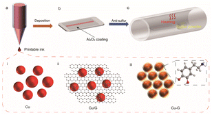
The corrosion of metallic materials is more acute when they are continuously exposed to atmospheres containing sulfur at elevated temperatures than in oxidizing environments.1 If the partial pressure of sulfur is low in atmospheres with a high amount of combustion gases, such as those found in energy-conversion processes, sulfur is unlikely to corrode oxidation-resistant metals/alloys. However, these oxidation-resistant metals/alloys undergo rapid deterioration in high-sulfide environments, particularly under high temperature, where even a trace of sulfur can cause catastrophic deterioration.2 Consequently, several strategies have been employed to improve the corrosion resistance of metals against sulfide corrosion in high-temperature applications. One strategy is to pre-oxidize the metal, which favors the formation and adhesion of a dense chromia or alumina coating with no physical defects on the core material.3 However, if the structural integrity is compromised in harsh environments, such as those found on Venus with its reactive sulfuric environment and high average surface temperature, corrosion could occur at high rates, destabilizing the structure and electrical conductivity of the metal components in electronic devices.4–7 Another strategy is to utilize high-temperature metallic materials for corrosion-resistant electronics,8 including noble metals, such as gold,9 silver,10 and palladium,11 and passive metals, such as nickel.12 Such high-temperature conductors offer high melting points, good electrical performance, and low heat expansion coefficients. However, prolonged exposure to a sulfur atmosphere could cause a 16% mean increase in resistance, with up to 30% at 150 °C. Therefore, it is necessary to seek alternative materials.13–15Metallic copper (Cu) provides high electrical and thermal conductivity;16,17 however, oxidation and corrosion resistance treatments involving alloying often compromise its electronic and thermal conductivity.18–20 To address these issues, enormous efforts have been devoted to using a robust and dense passivating layer to shield the conductor, enabling it to withstand extreme environments.21,22 Generally speaking, resistance to sulfur corrosion is achieved by applying a polymer coating on the Cu surface,23 such as resins, epoxy, and polyamides. However, these polymers are vulnerable to hydrolysis and degradation, and are not able to survive under high temperatures. Chitosan-based coatings24 and (2E,5E)-bis[(4-dimethylamino)benzylidene]cyclopentanone25 have also been investigated as corrosion inhibitors for Cu substrates under aqueous sulfuric acid. Chilkoor et al. coated Cu with hexagonal boron nitride (hBN) to prevent corrosion from sulfur compounds, and Cu–hBN showed seven times lower corrosion than bare Cu at room temperature.26 Here, we report the effective surface passivation of printed Cu conductors on Corning flexible Alumina Ribbon Ceramic to endow it with stability under high-temperature sulfur-containing environments. As shown in Fig. 1, the printed conductors examined in this study include a Cu/graphene physical mixture (Cu/G),27,28 hybridized Cu–graphene (Cu–G) from the in situ conversion of copper–dopamine complexes, and Cu featuring a conformal Al2O3 coating (Cu–Al2O3). We selected polydopamine, which can be carbonized at elevated temperatures in an inert atmosphere, to serve as a potent source of graphene in the printed Cu–G conductor, as it can form an adherent coating on the copper surface owing to its amine (–NH2) and hydroxyl (–OH) functional groups.27 Moreover, polymerization being an oxidative process helps in reducing surface oxides on the printed copper surface during the annealing step. In addition, we deposited an Al2O3 passive coating on printed copper, which serves as a defensive shield between copper and the corrosive environment. The as-fabricated graphene passivation layer and conformal Al2O3 coating provide oxidation and corrosion resistance to the printed Cu conductors under a high-temperature sulfurous atmosphere, while maintaining its high electrical conductivity of 4.42 MS m−1.
Experimental section
Synthesis of Cu NPs
First, the capping polymer polyvinylpyrrolidone (PVP) and reducing agent sodium phosphinate monohydrate (NaH2PO2·H2O) were dissolved in diethylene glycol (DEG) via heating and stirring. When the solution temperature reached 140 °C, aqueous copper sulfate was injected uniformly into the hot DEG solution via a syringe pump for the reaction. Then, the solution was naturally cooled to room temperature and copper nanoparticles (Cu NPs) were obtained by centrifugation. Finally, the Cu NPs were cleaned with methanol four times to remove any impurities. During the synthesis of Cu NPs, the PVP content and reaction time were varied to investigate their effects on the NP size.Printing Cu-based conductors
Hydroxypropyl methylcellulose (HPMC) solution (2 wt% in deionized water) and copper ink feedstock collected through centrifugation were mixed using an ARE-310 Thinky Mixer to prepare the conductive ink. Cu/G or Cu–G inks were prepared via the addition of graphene (5 wt% of the ink) or dopamine (5 wt% of the ink), respectively, and mixed to obtain a uniform ink. The printing of conductive ink was performed on a direct writing or ink-jet printer. Subsequently, the printed conductors coated onto Corning flexible Alumina Ribbon Ceramic were sintered under 95% nitrogen and 5% hydrogen at different temperatures to facilitate the removal of residual organics. Furthermore, polydopamine was converted to graphene in situ under high-temperature and forming gas conditions.Atomic layer deposition
A Savannah S100 atomic layer deposition (ALD) setup was used to deposit ultrathin Al2O3 films. The trimethylaluminum (TMA) precursor and H2O were sequentially exposed for 0.015 s with 8 s waiting time between the respective cycles and nitrogen purging at a rate of 20 sccm. The number of cycles was based on the desired thickness, and a thickness of 100 nm was deposited onto the printed feature on the flexible substrate. The deposition temperature was 200 °C.Morphological and structural characterization
Transmission electron microscopy (TEM) images were acquired on a JEOL JEM 2010 high-resolution TEM instrument. Scanning electron microscopy (SEM) and energy-dispersive X-ray spectroscopy (EDS) mapping images were captured on a ZEISS crossbeam FIB-SEM and Oxford EDS system, respectively. An SDT Q600 thermogravimetric analyzer was used to generate TGA curves. X-ray diffraction (XRD) patterns were recorded on a Rigaku Ultima IV instrument at a step of 5° min−1. The electrical characteristics were recorded on a Keithley 2450 source meter.Results and discussion
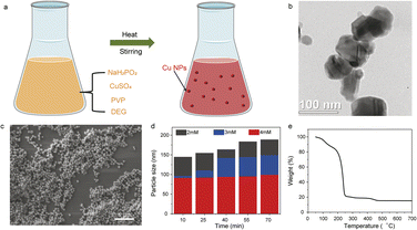
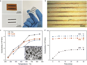
The printability and sintering profiles of Cu NPs depend on their synthesis-controlled dimensions obtained through the polyol process,29,30 involving diethylene glycol (DEG) as the solvent, polyvinylpyrrolidone (PVP) as the capping molecule, and sodium phosphinate monohydrate (NaH2PO2·H2O) as the reducing agent (Fig. 2a). As shown in Fig. 2b and c, the average size of the Cu NPs was 100 nm, and could be tuned by varying the amount of the encapsulating ligand PVP and reaction time (Fig. S1†). When the concentration of PVP was 2 mM, the average size of the Cu NPs ranged from 140 nm to 170 nm with the reaction time increasing from 10 min to 70 min (Fig. 2d). On increasing the PVP content to 3 mM, the average size of the Cu NPs increased from 95 nm to 145 nm under the reaction times of 10 min to 70 min. This suggests that the PVP ligand suppresses the growth and agglomeration of Cu NPs, while the size of the Cu NPs is controlled by the reaction time. Thermogravimetric analysis (TGA, Fig. 2e) of the printable Cu nanoparticle ink materials confirmed that the Cu solid content was about 20 wt%, with the decomposition of the organic ligand at 250 °C.The Cu NP inks were printed via both direct writing and ink-jetting onto different flexible substrates (paper, Kapton®, and Corning flexible Alumina Ribbon Ceramic; Fig. 3a and b). As shown in Fig. 3c, the electrical conductivity of the printed Cu features increased from 0.5 MS m−1 to 4.6 MS m−1 on increasing the sintering temperature from 250 °C to 850 °C, where the Cu NPs exhibited both sintering necks and long-range connections. Similar behavior was observed for the printed Cu/G and Cu–G conductors, whose electrical conductivities were 3.5 MS m−1 and 3.3 MS m−1 after heat treatment at 850 °C, respectively. It is worth noting that the sintering time is another key factor influencing electrical conductivity. Increasing the sintering time from 5 to 20 min at 250 °C increased the conductivity of the printed Cu features from 0.15 MS m−1 to 0.5 MS m−1, and then to 0.52 MS m−1 with a sintering time of 30 min (Fig. 3d). It was also observed that as the annealing temperature increased to 550 °C and 850 °C, the conductivity of the Cu conductor showed a subtle increase with increase in annealing time.
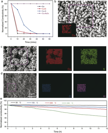
The sulfur-corrosion resistance of the Cu-based conductors was examined by evaluating the reliability of electric conductivity under a sulfurous atmosphere at various temperatures.31 Fig. S2† and 4a present the time-dependent conductivity of the printed Cu-based conductors (Cu, Cu/G, Cu–G, and Cu–Al2O3) at 35 and 150 °C, respectively. The conductivity of Cu decreased to 20% of its initial value after exposure to sulfur atmosphere at 35 °C for 10 min, and then broke after 60 min due to reaction with sulfur to form copper sulfide. Furthermore, the printed Cu conductors subjected to 10 min exposure to the sulfur atmosphere at 150 °C were quickly corroded by sulfur and became non-conductive. This was further confirmed by SEM and EDS elemental mapping images before (Fig. 4b) and after (Fig. 4c) sulfur corrosion. EDS indicated that these needle-like crystals were mainly composed of copper sulfide. Similarly, XRD analysis of the printed copper conductors before and after sulfur corrosion also confirmed the formation of copper sulfide (Fig. S3†). Graphene incorporation into the Cu conductors (both Cu/G and Cu–G) exhibited sulfur-corrosion resistance below 60 min. After exposure to a sulfurous atmosphere for 10 min at 150 °C, the conductivity of the Cu/G conductor decreased to 78% of its initial value, while the conductivity of the Cu–G conductor decreased by only 11%, indicating that the in situ-formed graphene passivation provided enhanced protection from sulfur corrosion. Fig. S4† shows the SEM and EDS images of the Cu/G conductor before and after sulfur corrosion. It is worth noting that the copper with a conformal Al2O3 coating layer with a thickness of 100 nm (Fig. 4d and S5†) showed no change in morphology before and after exposure to the sulfurous atmosphere, indicating that the Al2O3 coating protected the printed copper. Printed copper with Al2O3 coating showed robust sulfur resistance at 35 °C for more than 12 h, with a slight conductivity change of only 1% (Fig. 4e). When the temperature was increased to 150, 250 and 350 °C, the Cu–Al2O3 conductor maintained its reliability over 12 h, with the conductivity retention exceeding 95%, suggesting that this is a promising strategy to passivate Cu conductors to survive high-temperature sulfur environments.
Conclusion
In summary, the surface passivation of printed Cu-based conductors with graphene (physical mixing and in situ conversion) or an Al2O3 passivating layer afforded corrosion resistance under a high-temperature sulfurous atmosphere. The synthesized nanoparticles that formed the basis of this study could be printed using direct writing or ink-jetting onto different substrates, and the conductivity of the Cu NP conductor showed an increasing trend with increasing sintering temperature. When the printed conductor with a conformal 100 nm Al2O3 coating was exposed to a sulfur-containing environment at 350 °C for 12 h, the change in electric conductivity of the printed Cu conductor was less than 5%, maintaining a value of about 4.42 MS m−1. The proposed strategy provides the potential to extend the stability of copper conductors under extreme environments.Conflicts of interest
There are no conflicts to declare.Acknowledgements
Financial support was provided by the DEVCOM Army Research Laboratory, which supports S. R. under Award W911NF-20-2-0016 (conductive ink materials). High-temperature printable hybrid electronics is based on research sponsored by NextFlex through the Air Force Research Laboratory under Agreement Number FA8650-20-2-5506. The U.S. Government is authorized to reproduce and distribute reprints for governmental purposes notwithstanding any copyright notation thereon. The views and conclusions contained herein are those of the authors and should not be interpreted as necessarily representing the official policies or endorsements, either expressed or implied, of the Air Force Research Laboratory or the U.S. Government.References
- D. Meadowcroft and M. Manning, Corrosion Resistant Materials for Coal Gasification Systems, Applied Science, London, 1982 Search PubMed.
- S. Mrowec, Oxid. Met., 1995, 44, 177–209 CrossRef CAS.
- N. R. C. o. Canada, Compte rendu, National Research Council of Canada, 1984 Search PubMed.
- C. A. Sequeira, High Temperature Corrosion: Fundamentals and Engineering, John Wiley & Sons, 2019 Search PubMed.
- D. Lukco, D. J. Spry, P. G. Neudeck, L. M. Nakley, K. G. Phillips, R. S. Okojie and G. W. Hunter, J. Spacecr. Rockets, 2020, 57, 1118–1128 CrossRef CAS.
- P. G. Neudeck, L. Chen, R. D. Meredith, D. Lukco, D. J. Spry, L. M. Nakley and G. W. Hunter, IEEE J. Electron Devices Soc., 2019, 7, 100–110 CAS.
- M. J. Schuster, S. G. Brunner, K. Bussmann, S. Buttner, A. Domel, M. Hellerer, H. Lehner, P. Lehner, O. Porges, J. Reill, S. Riedel, M. Vayugundla, B. Vodermayer, T. Bodenmuller, C. Brand, W. Friedl, I. Grixa, H. Hirschmuller, M. Kassecker, Z. C. Marton, C. Nissler, F. Ruess, M. Suppa and A. Wedler, J. Intell. Rob. Syst., 2019, 93, 461–494 CrossRef.
- A. Sheng, S. Khuje, J. Yu, D. Petit, T. Parker, C. G. Zhuang, L. Kester and S. Ren, Nano Lett., 2021, 21, 9279–9284 CrossRef CAS PubMed.
- C. W. Corti and R. J. Holliday, Gold Bull., 2004, 37, 20–26 CrossRef CAS.
- T. Duy and H. Seo, Appl. Surf. Sci., 2020, 521, 146467 CrossRef.
- J. L. Tang, Z. H. Zhang, Y. Y. Wang, P. F. Ju, Y. M. Tang and Y. Zuo, Corros. Sci., 2018, 135, 222–232 CrossRef CAS.
- Y. K. Wei, Y. J. Li, Y. Zhang, X. T. Luo and C. J. Li, Corros. Sci., 2018, 138, 105–115 CrossRef CAS.
- R. He, Y. C. Wang, X. Wang, Z. Wang, G. Liu, W. Zhou, L. Wen, Q. Li, X. Wang, X. Chen, J. Zeng and J. G. Hou, Nat. Commun., 2014, 5, 4327 CrossRef CAS PubMed.
- M. Grouchko, A. Kamyshny and S. Magdassi, J. Mater. Chem., 2009, 19, 3057–3062 RSC.
- J. Peng, B. Chen, Z. Wang, J. Guo, B. Wu, S. Hao, Q. Zhang, L. Gu, Q. Zhou, Z. Liu, S. Hong, S. You, A. Fu, Z. Shi, H. Xie, D. Cao, C. J. Lin, G. Fu, L. S. Zheng, Y. Jiang and N. Zheng, Nature, 2020, 586, 390–394 CrossRef CAS PubMed.
- A. R. Rathmell, M. Nguyen, M. Chi and B. J. Wiley, Nano Lett., 2012, 12, 3193–3199 CrossRef CAS PubMed.
- Z. Chen, S. Ye, I. E. Stewart and B. J. Wiley, ACS Nano, 2014, 8, 9673–9679 CrossRef CAS PubMed.
- W. Shinato, A. A. Zewde and Y. Jin, Corros. Rev., 2020, 38, 101–109 Search PubMed.
- T. G. Kim, H. J. Park, K. Woo, S. Jeong, Y. Choi and S. Y. Lee, ACS Appl. Mater. Interfaces, 2018, 10, 1059–1066 CrossRef CAS PubMed.
- S. J. Eder, P. G. Grutzmacher, M. Rodriguez Ripoll, D. Dini and C. Gachot, Materials, 2020, 14, 60 CrossRef PubMed.
- G. Dingemans and E. Kessels, J. Vac. Sci. Technol., A, 2012, 30, 040802 CrossRef.
- L. Kovarik, M. Bowden, A. Andersen, N. R. Jaegers, N. Washton and J. Szanyi, Angew. Chem., Int. Ed. Engl., 2020, 59, 21719–21727 CrossRef CAS PubMed.
- Z. P. Kopteva, V. V. Zanina and I. A. Kozlova, Surf. Eng., 2004, 20, 275–280 CrossRef CAS.
- C. Giuliani, M. Pascucci, C. Riccucci, E. Messina, M. S. de Luna, M. Lavorgna, G. M. Ingo and G. Di Carlo, Prog. Org. Coat., 2018, 122, 138–146 CrossRef CAS.
- V. Thaçi, R. Hoti, A. Berisha and J. Bogdanov, Open Chem. J., 2020, 18, 1412–1420 Search PubMed.
- G. Chilkoor, K. Jawaharraj, B. Vemuri, A. Kutana, M. Tripathi, D. Kota, T. Arif, T. Filleter, A. B. Dalton, B. I. Yakobson, M. Meyyappan, M. M. Rahman, P. M. Ajayan and V. Gadhamshetty, ACS Nano, 2020, 14, 14809–14819 CrossRef PubMed.
- Z. Li, S. Khuje, A. Chivate, Y. Huang, Y. Hu, L. An, Z. Shao, J. Wang, S. Chang and S. Ren, ACS Appl. Electron. Mater., 2020, 2, 1867–1873 CrossRef CAS.
- A. Sheng, S. Khuje, J. Yu, D. Petit, T. Parker, C.-G. Zhuang, L. Kester and S. Ren, Nano Lett., 2021, 21, 9279–9284 CrossRef CAS PubMed.
- B. K. Park, S. Jeong, D. Kim, J. Moon, S. Lim and J. S. Kim, J. Colloid Interface Sci., 2007, 311, 417–424 CrossRef CAS PubMed.
- J. Ramyadevi, K. Jeyasubramanian, A. Marikani, G. Rajakumar, A. A. Rahuman, T. Santhoshkumar, A. V. Kirthi, C. Jayaseelan and S. Marimuthu, Parasitol. Res., 2011, 109, 1403–1415 CrossRef PubMed.
- J. Song, L. L. Wang, A. Zibart and C. Koch, Metals, 2012, 2, 450–477 CrossRef CAS.
Footnote |
| † Electronic supplementary information (ESI) available. See DOI: https://doi.org/10.1039/d2na00452f |
| This journal is © The Royal Society of Chemistry 2022 |


