 Open Access Article
Creative Commons Attribution 3.0 Unported Licence
Effect of conductivity, viscosity, and density of water-in-salt electrolytes on the electrochemical behavior of supercapacitors: molecular dynamics simulations and in situ characterization studies†
Débora A.
C. da Silva‡
 a,
Manuel J.
Pinzón C.‡
a,
Andresa
Messias
b,
Eudes E.
Fileti
a,
Manuel J.
Pinzón C.‡
a,
Andresa
Messias
b,
Eudes E.
Fileti
 *c,
Aline
Pascon
 a,
Débora V.
Franco
d,
Leonardo Morais
Da Silva
*d and
Hudson G.
Zanin
*a
aAdvanced Energy Storage Division, Center for Innovation on New Energies – Advanced Materials Labs, University of Campinas, Av. Albert Einstein 400, Campinas – SP, 13083-852, Brazil. E-mail: hzanin@unicamp.br
bCenter of Natural and Human Sciences, Federal University of ABC, 09210-170, Santo André, SP, Brazil
cInstitute of Science and Technology of the Federal University of São Paulo, 12247-014, São José dos Campos, SP, Brazil. E-mail: fileti@gmail.com
dDepartment of Chemistry, Laboratory of Fundamental and Applied Electrochemistry, Federal University of Jequitinhonha e Mucuri's Valley, Rodovia MGT 367, km 583, 5000, Alto da Jacuba, 39100-000, Diamantina – MG, Brazil. E-mail: leonardo.morais@ufvjm.edu.br
First published on 12th November 2021
Abstract
We report here molecular dynamics simulations combined with in situ experimental studies to understand the advantages and disadvantages of replacing conventional (salt-in-water, SiWE) aqueous-based electrolytes with very concentrated (water-in-salt, WiSE) systems in supercapacitors. Atomistic molecular dynamics simulations were employed to investigate the energetic, structural, and transport properties of aqueous electrolytes based on sodium perchlorate (NaClO4). Simulations covered the concentrations range of 1 mol dm−3 (1 mol kg−1) to 8 mol dm−3 (15 mol kg−1), demonstrating a significant increase in viscosity and density and reduction in ionic conductivity as the concentration reaches the WiSE conditions. A carbon-based symmetric supercapacitor filled with WiSE showed a larger electrochemical stability window (ESW), allowing to span the cell voltage and specific energy. Larger ESW values are possible due to the formation of a solvent blocking interface (SBI). The formation of ionic aggregates owing to the increasing cohesive energy in WiSE disturbs the hydrogen-bond network resulting in physicochemical changes in the bulk liquid phase. In addition, the molal ratio between water and ions is decreased, resulting in a low interaction of the water molecules with the electrode at the interface, thus inhibiting the water-splitting considerably.
1. Introduction
The growing demand for renewable energy sources has attracted attention to reduce the operational costs regarding the use of electrochemical energy storage devices.1,2 In this sense, Li-ion batteries, and supercapacitors (SCs) are widely employed devices for energy storage that are used in different technological applications. These different devices are complementary technologies for different applications (e.g., electric vehicles to portable electronics) since batteries have high specific energy while supercapacitors show high specific power characteristics.2–4 Nonetheless, the cost-effectiveness of lithium extraction in the earth's crust and the vulnerability it brings to projects in different countries have increased the attention of the scientific community.4–6 In this context, alternative technological strategies include the development of Na-ion batteries due to sodium abundance and high-performance aqueous-based supercapacitors which are more environmentally friendly compared to the traditional organic-based devices using toxic solvents.6,7 In addition, aqueous-based supercapacitors are an attractive technology due to high ionic conductivity, which decreases the equivalent series resistance (RESR), and the non-flammability characteristics.1 The major drawback regarding the use of aqueous-based supercapacitors is the reduced working voltage window (or electrochemical stability window – ESW) that limits the specific energy E = CU2/2, where C is the specific capacitance and U = ESW.5,8,9Several research groups have reported that highly concentrated aqueous-based electrolytes, especially water-in-salt electrolytes (WiSE), can mitigate the low energy limitation since the ESW values can be increased by manipulating the electrolyte properties.5,8,10,11 Conventional electrolytes (salt-in-water electrolytes, SiWE) used traditionally in energy storage devices have concentrations in the range of ∼1 to 2![[thin space (1/6-em)]](https://www.rsc.org/images/entities/char_2009.gif) mol dm−3.12 According to Suo et al.,12 in the case of WiSE, the salt-to-solvent ratio of volume or mass is higher than 1.0. In this sense, highly concentrated electrolytes have strong coordination characteristics that result in a ‘blocking ionic effect’ at the electrode/solution interface, i.e., the creation of a solvent blocking interface (SBI)13 considerably inhibits the water-splitting reaction, leading to larger ESW values.1,10 An effective electrolyte concentration affects the maximum cell voltage where the electrolyte is stable due to a complex combination of physicochemical phenomena induced by changes in the ionic strength, osmotic coefficient, and the activation barrier for electron transfer at the electrode/solution interface.
mol dm−3.12 According to Suo et al.,12 in the case of WiSE, the salt-to-solvent ratio of volume or mass is higher than 1.0. In this sense, highly concentrated electrolytes have strong coordination characteristics that result in a ‘blocking ionic effect’ at the electrode/solution interface, i.e., the creation of a solvent blocking interface (SBI)13 considerably inhibits the water-splitting reaction, leading to larger ESW values.1,10 An effective electrolyte concentration affects the maximum cell voltage where the electrolyte is stable due to a complex combination of physicochemical phenomena induced by changes in the ionic strength, osmotic coefficient, and the activation barrier for electron transfer at the electrode/solution interface.
The use of WiSE in SCs induces the presence of ‘compensating effects’ involving thermodynamic and kinetic components. In brief, the ‘salting-out effect’ reduces the partial pressure of the dissolved gases (O2 and H2) inside the coin cell to values lower than 1.0 bar. As a result, the equilibrium voltage for water-splitting is decreased from its standard value of 1.23 V predicted by thermodynamics.13,14 From the kinetic viewpoint for the electron transfer, the presence of dissipative effects associated with the ‘activation overpotential’ (Butler–Volmer's model) at the interface (e.g., Helmholtz compact layer) pushes the minimum (theoretical) voltage predicted for water-splitting to higher voltages13 due to the presence of an SBI. In this sense, from the kinetic viewpoint, the overpotential for the charge-transfer (water-splitting) reaction can be increased as a function of the electrolyte concentration due to an increase in the amount of specifically adsorbed ionic species that reduces the water activity at the electrode/electrolyte interface.
In the case of the conventional electrolytes denoted as SiWE the water concentration is very high (≈55 mol dm−3). Thus, the solvent dielectric constant in the bulk (εs ≈ 78 at 25 °C) dominates several electrolyte properties influenced by the ‘solute activity’ a± = γ± × m/m°, where γ± is the mean ionic activity coefficient, and m is the molality (m/mol kg−1).
As discussed by some authors,14,15 to investigate the changes in the transport properties exhibited by some Na-based electrolytes, as in the case of NaClO4 solutions, the non-linear behavior confirmed for the specific conductance and viscosity as a function of the electrolyte concentration could be interpreted assuming that the ionic species approached a distribution characteristic of crystal hydrate at high concentrations, i.e., near saturation conditions. In this sense, the aqueous quasi-lattice model discussed by Braunstein16 is essentially one of competing associations and hydration equilibria and is similar to the model proposed by Stokes and Robinson17 as an extension of the Debye–Hückel theory to concentrated solutions. In the case of WiSE, the distinction between solvent and solute is not straightforward since the ionic concentration is not so different from the water concentration. Also, due to the hydration phenomenon, each dissolved ionic species captures several water molecules in its solvation shell, i.e., the effective concentration of the ‘almost free’ water molecules not involved in the hydration process is very limited. As a result, solute and solvent properties are both important for WiSE.
Several studies have reported the expansion of the ESW using highly concentrated aqueous electrolytes based on Na-ions such as NaFSI,18 NaOTF-TEAOTF,19 NaOTF,20 and NaClO4.8 Among them, sodium perchlorate (NaClO4) has presented high performance and large ESW values. Nakamoto et al.8,21 reported high ionic conductivity (108 mS cm−1) and the expansion of ESW from 1.2 V to 2.8 V after increasing the sodium perchlorate concentration. Generally, WiSE permits to span the ESW values with changes in the intrinsic conductivity and a strong tendency to crystallization at the interface of the dissolved ionic species.22 For a particular electrolyte, intrinsic properties such as diffusivity, conductivity, and viscosity are also different for SiWE and WiSE systems.10 Therefore, the study of the molecular and transport properties exhibited by WiSE is crucial for a better understanding of the overall electrochemical behavior verified for WiSE-based SCs.
Although Sakamoto et al.5,8,21 have reported the ‘static structure’ of highly concentrated NaClO4 aqueous electrolytes, few detailed studies could be found in the literature on the molecular structure and dynamics of the ions in WiSE. In this sense, new studies regarding the NaClO4 electrolyte system are necessary for a better understanding of their physicochemical properties. In this work, the structural properties and the transport characteristics of the NaClO4 – based electrolyte at various concentrations are studied using atomistic molecular dynamics (MD) simulations. Additionally, experimental findings considering the behavior of the WiSE-based SCs were used to support the MD results.
2. Methodological section
2.1. Computational details
In this work the molecular properties of sodium perchlorate aqueous solutions in three and two concentrations for the SiWE (1, 2, and 5 mol dm−3) and WiSE (7 and 8 mol dm−3) systems are studied, respectively. For convenience, the conversion between molar (c/mol dm−3) and molal (m/mol kg−1) concentrations is presented in Table 1. The conversion between molality (m) and molarity (c) is given by the formula m = (1000 × c)/((1000 × ρsolution) − (c × W)), where W is the salt molecular mass. By definition, in this work, the SiWE and WiSE systems regarding the NaClO4 solutions are those with concentrations below and above 8.2 mol kg−1, respectively.10 All configurations were assembled using the PACKMOL package considering a cubic box with edges of 3.5 nm23 (please see Fig. 1).| Molarity (mol dm−3) | Molality (mol kg−1) | Ion Na | Ion ClO4 | Water molecules | Total interaction sites | Mass ratio (msalt/msolvent) |
|---|---|---|---|---|---|---|
| 1 | 1 | 20 | 20 | 1100 | 4520 | 0.12 |
| 2 | 2 | 36 | 36 | 1000 | 4216 | 0.24 |
| 5 | 7 | 89 | 89 | 990 | 4494 | 0.86 |
| 7 | 12 | 119 | 119 | 945 | 4494 | 1.47 |
| 8 | 15 | 133 | 133 | 925 | 4498 | 1.84 |
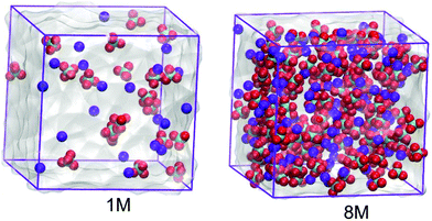 | ||
| Fig. 1 Molecular configurations of the 1.0 mol dm−3 and 8.0 mol dm−3 NaClO4 aqueous electrolytes. The anions are given in green and red while the cations are presented in blue. | ||
All potential models used to describe intermolecular interactions were based on the OPLS-AA force field.24 The water molecule was treated using the TIP4/2005 model,25 while the atomic partial charges and Lennard-Jones parameters of ClO4− ions were taken from the parametrization analysis using the RESP-A1A (HF/6-31G*) charge model.26,27 The Lennard-Jones parameters and atomic charges on the ions are listed in Table S1 (ESI†).
The equilibration of the electrolyte solutions was carried out in an isothermal–isobaric ensemble (NPT) for 10 ns, and the trajectory production was performed using the canonical ensemble (NVT) for 100 ns under normal conditions (T = 298 K and p = 1 atm). A Parrinello–Rahman barostat28 was utilized to maintain the constant pressure with a time constant of 2 ps and compressibility constant of 5 × 10⁻⁵ bar−1. To ensure a constant temperature, a Nosé–Hoover thermostat29 was used with a time constant of 2 ps. The Lennard-Jones interaction computed by the classical shifted force technique and long-range electrostatic correction estimated by the Particle–Mesh–Ewald method (PME)30 were applied beyond a cutoff radius of 0.9 nm. Periodic boundaries were employed in all directions. The integration time-step was 2.0 fs, and the coordinates and thermodynamic properties were stored every 0.1 ps. Table 1 shows the details of the investigated solutions.
Extended MD trajectory simulations were applied to obtain satisfactory accuracy for the electrolyte transport properties studied in this work. The standard deviation was assessed by dividing the trajectory into smaller blocks. 10 ns blocks were used for diffusion coefficients, while 30 ns blocks were considered for ionic conductivity analysis. The final values were obtained as the overall mean block and their corresponding standard deviations. All simulations were performed using the molecular dynamics GROMACS 2020 package.31
2.2. Experimental details
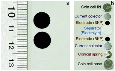
2.3. Electrochemical (in situ) experiments using different electrolytes
Cyclic voltammetry. A rough estimation of the ESWs for SiWE and WiSE systems was initially obtained from the CV experiments accomplished at 1.0 mV s−1 covering the voltage range of 1.2–1.7 V. After this, complementary SSC and EIS experiments were carried out to accurately determine the maximum ESWs attained for each electrolyte in the absence of water-splitting.
Single-step chronoamperometry. SSC experiments based on the Heaviside's step function34 (U(t) = 0 for t ≤ 0 and U(t) = ESW for t > 0) were conducted for 60 s, covering the voltage range of 1.2–1.7 V. Thus, considering the series canonic circuit model (RESR–CDLC) for well-behaved EDLCs, the transient current response is given by the relation Ic = I(t→0) × exp(−t/τ), where I(t→0) = (δU/RESR) is the current expected after application of the H-step voltage perturbation (δU), and τ = RESR × CDLC is the time constant. Conversely, a faradaic current (If) due to an irreversible electrode reaction (e.g., water-splitting) is governed by Faraday's law, i.e., without a transient behavior, since If ≅ constant for a particular U-value. Therefore, a background (parasitic) current, after ca. 10–30 s in the SSC experiments, commonly indicates electrolyte decomposition. Even so, in some cases, additional experiments using the impedance technique may be necessary to confirm the occurrence of water-splitting.
Electrochemical impedance spectroscopy. EIS experiments are highly sensitive for detecting the presence of very small faradaic currents corresponding to a charge-transfer resistance (RCT). Therefore, impedance data were obtained by applying a 10 mV (peak-to-peak) amplitude covering the frequency range of 10 kHz to 10 mHz. The d.c. voltages (U = 1.2–1.7 V) were the same used in the CV and SSC experiments. In the presence of water-splitting, the interface phenomenon is represented by the Randles simplified equivalent circuit (RESR − [RCT||CDLC]), where the equivalent series resistance (RESR) appears in series with the parallel combination between the double-layer capacitance (CDLC) and the charge-transfer resistance (RCT). Instead of a ‘straight line’ represented by RESR − CDLC, the former model predicts a poorly developed semicircle in the low-frequency range of the complex plane while a very high RCT value corresponds to the parasitic current.
Galvanostatic charge–discharge. GCD experiments were conducted by applying specific (gravimetric) currents in the range of 0.25 to 4 A g−1. The voltage range used in the GCD experiments corresponded to the ESW values obtained in the SSC and EIS experiments (see the Results and discussion section). In this sense, the following equations were used to calculate the specific capacitance (Cg), energy density (Es), and power density (Ps):35,36
| Cg = I/(m × (dU/dt)) | (1) |
| Es = (Cg × (ESW)2)/7.2 | (2) |
| Ps = (Es × 1800)/(Cg × ESR × m) | (3) |
The ESR values were determined from the GCD data using the relation RESR = ΔUdrop/2I.36 All electrochemical measurements were performed using a model BSC-810 potentiostat cycler system from BioLogic®.
3. Results and discussion
3.1. MD simulations
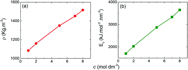 | ||
| Fig. 3 Mass density (a) and cohesive energy (b) determined from the MD simulations as a function of the molar concentration of the NaClO4-based electrolyte. | ||
The total intermolecular interactions in solution are quantified by the cohesive energy (Ec), which was computed through the ratio between the internal energy of vaporization (ΔUvap) and the liquid molar volume (Vm):38,39
| Ec = (ΔUvap)/Vm | (4) |
For energy of vaporization, we considered only the intermolecular interactions. Similarly to mass density, the cohesive energy increased with molar concentration, presenting higher values for WiSE than SiWE. This result may be associated with the greater number of ClO4− anions present in WiSE. As reported by Yin et al.,40–42 the anion ClO4− produces a structure-breaking effect, which breaks the hydrogen bond network between the water molecules, but forms new ones between anions and water. This effect increases the internal energy of vaporization of the electrolyte and, consequently, its cohesive energy.39 For practical devices used in electric vehicles or mobile devices, for instance, electrochemical cells may have operational conditions above 40 °C, which usually reduces energy efficiency considerably. That is why high cohesive energy is desirable for better thermal stability.43,44
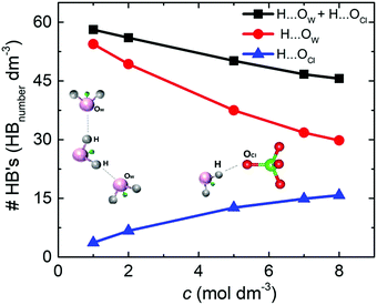
The density of hydrogen bonds (#HB's) was determinate by the average number of O⋯H hydrogen bonds per volume for the different NaClO4 molar concentrations. For both solutions, SiWE and WiSE, the density of hydrogen bonds formed between water molecules (e.g., H⋯OW, red curve) is more significant than between water and anions (e.g., H⋯OCl, blue curve), as shown in Fig. 4.
Note that the total density of hydrogen bonds (black curve) decreases with concentration, following the increase of cohesive energy (please see Fig. 3(b)). The higher concentration of ions leads to a drastic increase in electrostatic interactions in the bulk, which dominate the intrinsic energy of WiSE. Table 2 presents the decomposition of cohesive energy (Ec) into its coulombic (ECoul.) and van der Waals (EvdW) components. As the concentration rises, the increase in coulombic contribution in magnitude is observed, as well as decrease in the van der Waals component. In all the cases, the increase in coulombic energy dominates the cohesive energy. One issue here is that the formation of NaClO4 in solution or at the electrode/electrolyte interface affects the electrolyte interaction with the electrode. Increasing coulomb forces will reduce ionic mobility, and salt adsorption at the electrode/electrolyte interface forms the solvent blocking interface (SBI).13 The latter phenomenon was briefly mentioned in the Introduction section, i.e., an SBI can be responsible for the charge-transfer hindrance related to water-splitting during cell polarization at high voltages (see further discussion in this work).
| c/mol dm−3 | E Coul./kJ mol−1 nm−3 | E vdW/kJ mol−1 nm−3 | E c/kJ mol−1 nm−3 |
|---|---|---|---|
| 1 | −2234 | 283 | −1951 |
| 2 | −2553 | 272 | −2281 |
| 5 | −3380 | 243 | −3137 |
| 7 | −3832 | 228 | −3603 |
| 8 | −4104 | 190 | −3914 |
 | ||
| Fig. 5 Radial distribution functions for the center-of-mass for Na–water, ClO4–water and Na–ClO4 as a function of the molar concentration. | ||
| c/mol dm−3 | Na–water | ClO4–water | Na–ClO4 |
|---|---|---|---|
| 1 | 5.6 | 19.8 | 0.4 |
| 2 | 5.5 | 19.5 | 0.6 |
| 5 | 4.7 | 17.8 | 1.3 |
| 7 | 4.4 | 16.8 | 1.7 |
| 8 | 4.3 | 16.8 | 2.0 |
Fig. 5(b) shows the RDF for ClO4–water. The maximum of the first peak is observed at ≈0.37 nm, with the first and second minima at 0.54 nm and 0.88 nm, respectively. Peak positions and heights are in agreement with the literature reports.26,45,47 It can be observed that as the concentration increases, the height of the first peak and the depth of the first minimum also increases, indicating a more significant structuring in WiSE than in SiWE (normal) electrolytes.
Finally, Fig. 5(c) shows the RDF for Na–ClO4 pairs. The radius of the first hydration shell identified as the RDF minimum is 0.43 nm. From the second peak at 0.55 nm, it can be asserted that the increased number of anions in the second hydration shell makes it more diffusive. In addition, the number of ClO4− anions in the first hydration shell increased from 0.4 at 1 M to 2.0 at 8 M. The increase of the coordination number verified for the Na–ClO4 pairs indicates a strong association between Na+ and ClO4−.
A complementary electrolyte structural analysis can be done in terms of the spatial distribution function (SDF). This analysis covers the radial and angular coordinates of the interatomic distance vector. It can precisely describe the three-dimensional density distribution of a solvent in a local coordinate system attached to a solute molecule. Here, in terms of SDF, the three-dimensional solvation structure for the water and cations around the ClO4− anions was calculated according to Brehm et al.48,49Fig. 6 shows the isosurfaces for the sodium cations and the water molecules distributed around the ClO4− anion.
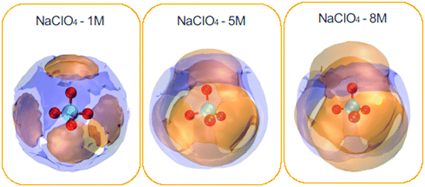 | ||
| Fig. 6 Spatial density functions (SDF) of the neighboring water molecules (purple surface) and Na+ ions (orange surface) around the ClO4− species. NaClO4 concentrations: 1, 5, and 8 M. | ||
In general, cations present around the anions are much more pronounced compared to water molecules. In addition, one can see the complementary character of the two SDFs obtained for water and cations. Cations are distributed directly in front of each oxygen atom, forming four very different caps, and water molecules come to occupy the interstitial space of this distribution. It can also be seen that the spatial density distribution for the cations increases with the concentration from 1 to 8 M. On the contrary, the water distribution follows an opposite trend. This result is related to the coordination number of the water molecules, which decreases around the ClO4− anion with increasing concentration (see Table 3). SDF of Na+ ions shows clear coordination around the ClO4− anion, indicating a strong association between the ionic pairs. It can be seen that the water molecules and Na+ ions were tetracoordinate to the ClO4− ion for the different NaClO4 molar concentrations.
 | (5) |
Fig. 7 shows the shear viscosity for each NaClO4 concentration (red curve). As expected, the shear viscosity increases (almost linearly) with molar concentration. This behavior also has been experimentally observed by Bu and co-workers.10 Here, from 1 M to 8 M is reported a rise of 80% in viscosity. The increase of viscosity may be related to the shift of the band of stretching of the ion ClO4− (υ1), which implies the formation of ionic pairs and ionic aggregates (CIP/AG) in solution. (Please see further discussion on Raman analysis of electrolyte.) This way, the formation of CIP/AG affects viscosity as well as ionic mobility; furthermore, this may be the possible cause for the formation of SBI.13
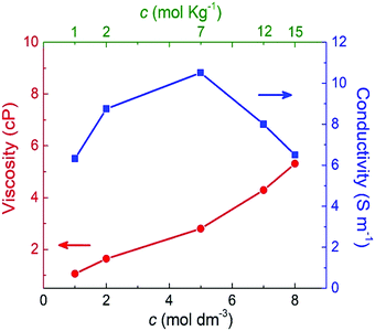 | ||
| Fig. 7 Shear viscosity and ionic conductivity as a function of the molar and molal concentrations of NaClO4 aqueous solutions. | ||
The Einstein–Helfand method was applied for the ionic conductivity calculations, which is based on the linear slope of the mean displacement of the collective translational dipole moments (Mj):27
 | (6) |
The blue curve in Fig. 7 indicates that the ionic conductivity reaches its maximum value of 10.5 S m−1 at 5 M (or 7 molal). A minimum conductivity of 6.5 S m−1 was verified for the minimum (1 M) and maximum (8 M or 15 molal) concentrations. These results point out that a concentration above 5 M (or 7 molal) negatively impacted ionic conductivity. This profile is in agreement with the experimental findings reported by R. Sakamoto et al.5 who observed a decrease of NaClO4 ionic conductivity above 7 mol kg−1.
These findings highlight the significant difference between SiWE and WiSE. It is well-known that highly diluted ionic solutions follow Walden's rule, which establishes that the limiting molar conductance (λ0m) is inversely proportional to viscosity (η0).50 In the case of NaClO4 aqueous solutions, λ0m × η ≈ 1.17 in the 283–313 K interval. Also, diluted SiWE follows the Debye–Hückel–Onsager theory given by equation Λm = Λ0m − (A + BΛ0m)c1/2, where Λm = Λ/m, and A and B are empirical constants for a particular electrolyte solution. In this work, it has been confirmed that the molal conductivity is given by the correlation Λm = 0.46 + 7.35exp(−0.304m) (please see Fig. S2 and S3, ESI†).
Yin et al.41 reported experimentally that for NaClO4 concentrations in the range of 0.1 to 5 M, the supercapacitors using a 5 M solution showed higher ionic conductivity and specific capacitance among all the analyzed concentrations.
As the last analysis is concerned with the ionic mobility assessed by the diffusion coefficients (D), the latter parameter can be evaluated from the linear adjustment of the mean quadratic displacement of ri:27
 | (7) |
Fig. 8 compares the ionic diffusion coefficient for water, Na+, and ClO4−. As expected, the diffusion coefficients decrease as a function of the electrolyte concentration. This tendency is in agreement with the previous experimental studies reported by Heil et al.51
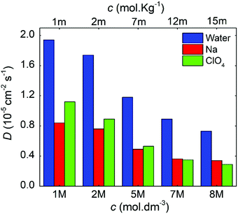 | ||
| Fig. 8 Diffusion coefficients as a function of the molal and molar concentrations for the NaClO4 aqueous electrolytes. | ||
For all cases, water presents higher diffusivity than the ions by ∼50%. The water diffusion coefficient decreased from 1.90 × 10⁻⁵ to 0.73 × 10⁻⁵ cm2 s−1 when the concentration increased from 1 to 8 M, respectively. This reduction is related to a molar ratio decrease from 55.0 to 6.9, which impacts directly on the mobility of the different solution species.38,52 All ions followed a similar trend, but it is worth mentioning that for 7 M, the diffusion of ClO4− became lower when compared to that of Na+. The ClO4− diffusion is affected by the reduction in ionic mobility at higher concentrations and its relative size compared to Na+.
Generally, the MD simulation findings revealed that all investigated electrolyte properties (e.g., energetic, structural, and transport) depend on the NaClO4 concentration. These findings are in agreement with the literature.5,41 Several studies have reported the advantages of using WiSE for expanding the ESW in SCs.8,10,21,53 However, as the MD results suggested, this advantage does not come from any specific properties of electrolytes, especially concerning viscosity and ionic conductivity. These properties have a prominent role in the bulk electrolyte characteristics. On the contrary, spanning the ESW also depends on the charge-transfer kinetics at the electrode/solution interface. As will be seen, interesting findings were obtained in the electrochemical studies.
3.2. Experimental results
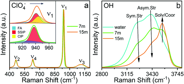
The sub-band located in the low-frequency region (ca. ∼ 928.8 cm−1) is related to the presence of free anions in solution (henceforth FA). A second band, ascribed to solvent separated ion pairs (SSIP), occurs at 937.6 cm−1 for the electrolyte of concentration 7m and then shifts to 939.6 cm−1 for the concentration 15m. The band located at 943.4 cm−1 that appears in the WiSE concentration is associated with the changes in the solvation layers of the anion due to coordination with the cation, forming contact ion pairs and ionic aggregates (CIP/AG). It is remarkable how the intensity of the sub-band of free anions decreases with increasing concentration, confirming the results obtained by simulation presented in Fig. 5 and 6. Fig. 9(b) clearly shows the change in the activity of the water molecules with increasing concentration. The bands associated with the vibrational stretching modes symmetric (∼3243 cm−1) and asymmetric (∼3413 cm−1) fade dramatically at the same time when a band emerges in the high-frequency region related in the previous studies with the coordination of the water around the cation, which from our point of view is only partially true, since it does not take into account that at high concentrations there is a considerable population of CIP/AG which would indicate that the band (∼3555 cm−1) should be associated with the presence of water molecules around the aggregates and ionic pairs.5 The formation of CIP/AG and the modification in the environment and the activity of the water molecules, shown by the results of the Raman analysis, confirm the behavior predicted by the computational analysis. As shown in Fig. 4, the total density of hydrogen bonds decreases with increasing concentration, which is due not only to the decrease in the number of water molecules, but also to the effect that the anion has on the network of such links. As the concentration increases, the anions are surrounded by a greater number of water molecules in two different configurations. The first configuration is that of separated solvated ions and the second as solvation layers of CIP/AG. Additionally, the formation of ionic pairs and aggregates can be explained from the computational results, with what is presented in Fig. 3(b) and in Fig. 6, since the increase in cohesive energy is directly related to the increase in molecular interactions, which is expressed as an increase in cation density around ClO4−.
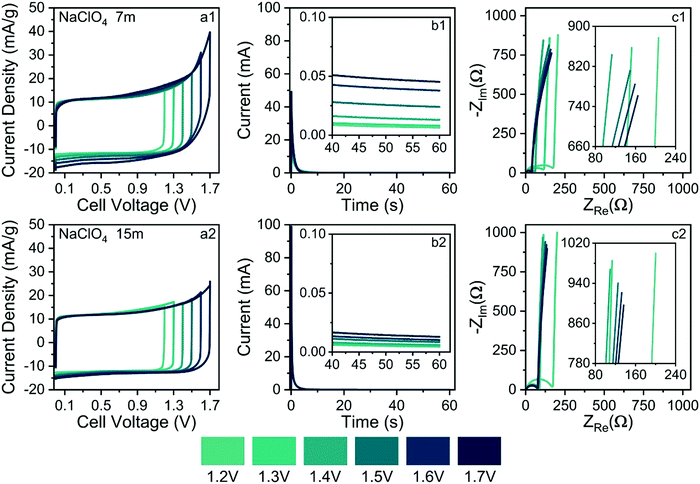
For the different molalities (m/mol kg−1), the CV findings showed an almost ideal electrical double-layer capacitance (EDLC) behavior characterized by symmetric rectangular voltammetric profiles up to U ≈ 1.3 V. The upward anodic current following an exponential trend verified at ca. U > 1.3 V denounces the onset of electrolyte decomposition, as predicted by the well-known Butler–Volmer's model (If ≅ I0exp(αFη/RT), when η > 0.1 V), which represents the electron transfer kinetics at the electrode/electrolyte interface. In the model, η ≡ U − 1.23 V is the overpotential for water-splitting, while the ‘kinetic parameters’ are the exchange current density (I0) and the charge-transfer (or symmetry) coefficient (α). As is already known F is the Faraday constant, R is molar gas constant and T is the absolute temperature. At low scan rates (e.g., ν ≤ 1 mV s−1), the faradaic current (If) is large compared to the capacitive current (Ic = Cedlν) since the former current does not depend on the voltage scan rate (ν). Therefore, the CV technique alone is not recommended to determine the maximum ESW in SCs.33 Unfortunately, in several cases, the maximum ESW values are incorrectly evaluated at high scan rates leading to misleading findings since the faradaic current due to water-splitting can be masked by the capacitive current.
As commented in the Introduction section, highly concentrated electrolytes typically reduce the onset of the water-splitting reaction. In this sense, Fig. 10(b1) and (b2) show the SSC findings (e.g., current transients & residual currents) for the different applied voltages and electrolyte concentrations. The analysis of current transients makes it possible to discriminate the capacitive and faradaic responses.33 For well-behaved SCs, the transient capacitive current (Ic) is given by the relation Ic = (δU/RESR)exp(−t/RESR × CCDE), where δU is the applied voltage step, RESR is the equivalent series resistance, CCDE is the capacitance of the device, and (δU/RESR) ≡ I(t→0) is the initial current measured at t = 0. For most laboratory-made coin cell devices, which exhibit a small time constant (τ = RESR × CCDE), the capacitive current must practically fade away, corresponding to a current reduction (e.g., Ic/I(t→0) × 100%) of ca. 99.9%, after ≈10–20 s. Therefore, the verification of non-negligible stationary (residual) currents (≥0.1%) in the SSC experiments indicates the occurrence of water-splitting.
From the above considerations, current transients were recorded up to 60 s to determine the magnitude of the residual current at t > 10 s. In the case of Fig. 10(b1) and b(2), current reductions of 0.1% and 0.025%, respectively, were observed for different electrolytes at 1.7 V. Therefore, in light of the SSC experiments, one can discard the occurrence of water-splitting in the case of the 15.0 mol kg−1 NaClO4 (WiSE) solution. In the case of the SiWE (7.0 mol kg−1 NaClO4) system, additional evidence obtained from the EIS technique is necessary to discriminate the occurrence of water-splitting at very low current levels.
The analysis of the low-frequency data in the complex-plane plots gives information regarding the occurrence of water-splitting. Thus, EIS findings were obtained applying the same voltages used in the CV and SSC experiments. Deviations from the linearity (r2 < 0.997) verified in the complex-plane plot at low frequencies (f ≤ 1 Hz) confirm the presence of water-splitting since the impedance response is no longer purely capacitive. Indeed, the presence of a charge-transfer resistance (RCT) in parallel to the electrical double-layer charging process (CDCL) results in a poorly developed semicircle at low frequencies that can be identified using the complex non-linear least squares (CNLS) method of simulation.
Fig. 10(c1) and (c2) show the complex-plane plots for the NaClO4-based SCs at different voltages. Generally, well-behaved SCs are characterized by low-frequency phase angles (φ) greater than ca. −83°, i.e., from the perspective of the constant phase element (CPE) approach, used to represent the frequency dispersion phenomenon intrinsic to solid electrodes, where Zcpe = 1/Y0(jω)n; a good SC behavior is associated with ca. n > 0.95 where Y0 ≅ Cedl. Obviously, the unit of a true capacitance is the farad (F ≡ s Ω−1), while in the case of a CPE, one has the fractal unity given by F sn−1. The conversion between Y0 and Cedl can be done using the Brug–Sluyters’ formula.
In the case of data shown Fig. 10(c1), the linear regression analysis using the R−CPE circuit model revealed an excellent linear correlation only for U ≤ 1.4 V. Therefore, the maximum ESW value in the case of the SiWE system is 1.4 V. On the contrary, in the WiSE system, the impedance analysis confirmed the maximum ESW value of 1.6 V.
In principle, the electrochemical findings were in agreement with the energetic and structural properties extracted from MD simulations, where the formation of an SBI structure is predicted for WiSE systems. Since SiWE has high ionic conductivity and many free water molecules compared to WiSE, the former system does not form an SBI structure. Therefore, the water molecules in the case of SiWE directly interact with the electrode's surface at high voltages (e.g., strong electric fields of ≈107 V cm−1), permitting the occurrence of charge-transfer kinetics accounting for water-splitting. After all, the lower diffusivity of water molecules in highly concentrated electrolytes reflects a decreased ionic mobility, formation of a solid barrier interface, or the presence of an SBI structure. As a result, the charge-transfer (faradaic) reaction was strongly inhibited at higher voltages for the WiSE system.
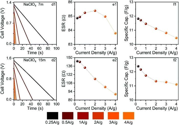
Fig. 11 shows the findings obtained from the galvanostatic charge–discharge experiments.
The ESW values previously determined in this study were applied in the GCD experiments. As seen in Fig. 11, the GCD curves are linear as expected for well-behaved EDLCs. The applied current densities from 0.25 to 4 A g−1 affected the different electrochemical parameters. For the SiWE system, the ESR values changed from 84.8 to 83.7 Ω with a maximum relative variation (r.v.) of 1.3%. At the same time, the specific capacitance (Cs) decreased from 11.9 to 10.5 to F g−1 (r.v. = 13.3%). In the case of the WiSE system, the corresponding changes were 143 to 87 Ω (r.v. = 64.4%) and 12.4 to 11.2 to F g−1 (r.v. = 10.7%), respectively.
As seen, there was a significant increase in ESR when the electrolyte concentration was increased from 7.0 to 15 mol kg−1. According to the present MD simulations, higher ESR values are indeed expected for WiSE, i.e., highly concentrated solutions have reduced ionic mobility (conductivity) due to the strong degree of ionic association caused by the short- and long-range coulombic interactions, as well as the lower availability of the free solvent molecules. On the contrary, the specific capacitance was not strongly affected by the molality, probably due to a facile insertion of the ionic species into carbon mesopores. In this sense, specific capacitance is less affected by molality since the interface charge-storage process is directly related to the electrochemically active surface area where the carbon mesoporous structures have a relatively large dimension compared to the ion sizes. Therefore, one can propose that the NaClO4-based WiSE increased the ESR but with less pronounced effects on the interfacial phenomenon (double-layer capacitance). In fact, as briefly mentioned in the Introduction section, the major influence of molality on the electrical double-layer behavior is due to local changes in the dielectric constant.
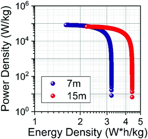
The specific energy Es (W h kg−1) and power Ps (W kg−1) of SCs were calculated from the ESR and Cs values.57Fig. 12 shows the Ragone plot obtained for the SiWE and WiSE systems. As can be seen, the use of NaClO4-based WiSE promoted a relative increase of ∼38% for the specific energy and power. Therefore, the increase verified for ESR is compensated by the large ESWs found in highly concentrated solutions (see Fig. 10).
4. Conclusions
We have reported the energetic, structural, and dynamic properties of aqueous electrolytes based on sodium perchlorate (NaClO4) in two regimes: conventional (SiWE) and highly concentrated (WiSE), by atomistic molecular dynamics simulations and experimental approaches. Our results clarify the differences between SiWE and WiSE. We have seen that densities and cohesive energies vary dramatically with increasing concentration from 1 mol dm−3 (1 mol kg−1) to 8 mol dm−3 (15 mol kg−1). Furthermore, at the same concentrations mentioned above, the structural properties showed significant differences, especially about the coordination of the Na+–OCl ion pairs, which increased by a factor of five. These results were confirmed by the analysis of the spatial distribution functions, which shows an increased sodium coordination around the perchlorate anion as the concentration increases and also by the Raman spectra analyses that show that the said increase in anion–cation coordination is due to the formation of contact ion pairs and ionic aggregates. Thermodynamic properties are usually susceptible to variation in concentration, and our results have confirmed that. The viscosity suffered a significant variation, going from 1.06 cP at 1 mol dm−3 to 5.31 cP at 8 mol dm−3. The ionic conductivity increases to a maximum at 10.5 S m−1 for the 5 mol dm−3, and then decreasing again, reaching 6.5 S m−1 at 8 mol dm−3. Both results for viscosity and conductivity are directly linked to ionic mobility, which is measured by the diffusion coefficient and has also been significantly reduced with increasing concentration. Our results indicate WiSE does not have typical properties expected for an aqueous electrolyte (for example, low viscosity and high conductivity). We observed WiSE has higher density and viscosity and lower ionic conductivity. These findings come from the strong degree of ionic association caused by the short- and long-range coulombic interactions, as well as lower availability of the free solvent molecules which increase the ESR. Nonetheless, we have noted that WiSE electrolytes presented increase the ESW and consequently cell's energy density. Such expansion is possible because solvent blocking interface blocks water to contact polarized electrode i.e., all available water molecules are solvating structure of both ions (ClO4− and Na+), that decrease the hydrogen bonds between the water molecules, generating a perfect environment for the formation of SBI. In addition, we found that the specific capacitance was not strongly affected by the molality, which may be related to the relatively large dimension of carbon mesoporous structures that make the insertion of the ionic species into carbon mesopores easy. In conclusion, the results presented here provide a better understanding of the advantages and disadvantages of using WiSE electrolytes in supercapacitors in light of their energy, structural and transport properties.Conflicts of interest
There are no conflicts to declare.Acknowledgements
The authors are very grateful for the financial support from the Brazilian funding agencies CAPES (PROEX 88887.374731/2019-00 and Print-CAPES (8887.572651/2020-00)), and São Paulo Research Foundation - FAPESP (2017/11958-1 & 2014/02163-7). L.M. Da Silva wishes to thank the Minas Gerais Research Foundation - FAPEMIG. H. Zanin and L. M. Da Silva wish to thank the National Council for Scientific and Technological Development - CNPq for the PQ-2 grant (310544/2019-0). The authors gratefully acknowledge the financial support from Shell and the strategic importance of the support given by ANP (Brazil's National Oil, Natural Gas, and Biofuels Agency) through the R&D levy regulation.References
- D. Larcher and J. M. Tarascon, Nat. Chem., 2015, 7, 19–29 CrossRef CAS.
- J. B. Goodenough and Y. Kim, Chem. Mater., 2010, 22, 587–603 CrossRef CAS.
- B. Scrosati and J. Garche, J. Power Sources, 2010, 195, 2419–2430 CrossRef CAS.
- V. Etacheri, R. Marom, R. Elazari, G. Salitra and D. Aurbach, Energy Environ. Sci., 2011, 4, 3243–3262 RSC.
- R. Sakamoto, M. Yamashita, K. Nakamoto, Y. Zhou, N. Yoshimoto, K. Fujii, T. Yamaguchi, A. Kitajou and S. Okada, Phys. Chem. Chem. Phys., 2020, 22, 26452–26458 RSC.
- A. Ponrouch, D. Monti, A. Boschin, B. Steen, P. Johansson and M. R. Palacín, J. Mater. Chem. A, 2015, 3, 22–42 RSC.
- D. Monti, E. Jónsson, A. Boschin, M. R. Palacín, A. Ponrouch and P. Johansson, Phys. Chem. Chem. Phys., 2020, 22, 22768–22777 RSC.
- K. Nakamoto, R. Sakamoto, M. Ito, A. Kitajou and S. Okada, Electrochemistry, 2017, 85, 179–185 CrossRef CAS.
- H. Kim, J. Hong, K. Y. Park, H. Kim, S. W. Kim and K. Kang, Chem. Rev., 2014, 114, 11788–11827 CrossRef CAS.
- X. Bu, L. Su, Q. Dou, S. Lei and X. Yan, J. Mater. Chem. A, 2019, 7, 7541–7547 RSC.
- R.-S. Kühnel, D. Reber and C. Battaglia, J. Electrochem. Soc., 2020, 167, 070544 CrossRef.
- L. Suo, Y. S. Hu, H. Li, M. Armand and L. Chen, Nat. Commun., 2013, 4, 1–9 Search PubMed.
- P. Kulkarni, D. Ghosh and G. Balakrishna, Sustainable Energy Fuels, 2021, 5, 1619–1654 RSC.
- J. W. Morales, H. R. Galleguillos, F. Hernández-Luis and R. Rodríguez-Raposo, J. Chem. Eng. Data, 2011, 56, 3449–3453 CrossRef CAS.
- G. J. Janz, B. G. Oliver, G. R. Lakshminarayanan and G. E. Mayer, J. Phys. Chem., 1970, 74, 1285–1289 CrossRef CAS.
- J. Braunstein, J. Phys. Chem., 1967, 71, 3402–3407 CrossRef.
- R. H. Stokes and R. A. Robinson, J. Am. Chem. Soc., 1948, 70, 1870–1878 CrossRef CAS.
- D. Reber, R. S. Kühnel and C. Battaglia, Sustainable Energy Fuels, 2017, 1, 2155–2161 RSC.
- L. Jiang, L. Liu, J. Yue, Q. Zhang, A. Zhou, O. Borodin, L. Suo, H. Li, L. Chen, K. Xu and Y. S. Hu, Adv. Mater., 2020, 32, 1–10 Search PubMed.
- L. Suo, O. Borodin, Y. Wang, X. Rong, W. Sun, X. Fan, S. Xu, M. A. Schroeder, A. V. Cresce, F. Wang, C. Yang, Y. S. Hu, K. Xu and C. Wang, Adv. Energy Mater., 2017, 7, 1–10 Search PubMed.
- K. Nakamoto, R. Sakamoto, Y. Sawada, M. Ito and S. Okada, Small Methods, 2019, 3, 1–5 Search PubMed.
- M. Chen, G. Feng and R. Qiao, Curr. Opin. Colloid Interface Sci., 2020, 47, 99–110 CrossRef CAS.
- L. Martínez, R. Andrade, E. G. Birgin and J. M. Martínez, J. Comput. Chem., 2009, 30, 2157–2164 CrossRef PubMed.
- W. L. Jorgensen, D. S. Maxwell and J. Tirado-Rives, J. Am. Chem. Soc., 1996, 118, 11225–11236 CrossRef CAS.
- J. L. F. Abascal and C. Vega, J. Chem. Phys., 2005, 123, 1–12 CrossRef.
- K. Nieszporek, P. Podkościelny and J. Nieszporek, Phys. Chem. Chem. Phys., 2016, 18, 5957–5963 RSC.
- K. Nieszporek, J. Nieszporek and M. Trojak, Comput. Theor. Chem., 2016, 1090, 52–57 CrossRef CAS.
- M. Parrinello and A. Rahman, J. Appl. Phys., 1981, 52, 7182–7190 CrossRef CAS.
- G. J. Martyna, M. L. Klein and M. Tuckerman, J. Chem. Phys., 1992, 97, 2635–2643 CrossRef.
- T. Darden, D. York and L. Pedersen, J. Chem. Phys., 1993, 98, 10089–10092 CrossRef CAS.
- M. J. Abraham, T. Murtola, R. Schulz, S. Páll, J. C. Smith, B. Hess and E. Lindah, SoftwareX, 2015, 1–2, 19–25 CrossRef.
- M. M. Amaral, M. J. Pinzón C., A. C. Peterlevitz, C. A. Rufino Júnior, L. M. Da Silva and H. Zanin, Diam. Relat. Mater., 2021, 115, 108354 CrossRef CAS.
- W. G. Nunes, B. G. A. Freitas, R. M. Beraldo, R. M. Filho, L. M. Da Silva and H. Zanin, Sci. Rep., 2020, 10, 1–9 CrossRef.
- D. Baowan, B. J. Cox, T. A. Hilder, J. M. Hill and N. Thamwattana, Modelling and Mechanics of Carbon-Based Nanostructured Materials, Elsevier, Oxford, 2017 Search PubMed.
- A. Noori, M. F. El-Kady, M. S. Rahmanifar, R. B. Kaner and M. F. Mousavi, Chem. Soc. Rev., 2019, 48, 1272–1341 RSC.
- S. Zhang and N. Pan, Adv. Energy Mater., 2015, 5, 1–19 Search PubMed.
- T. R. Kartha and B. S. Mallik, Mater. Today Commun., 2020, 25, 101588 CrossRef CAS.
- P. Inoue, E. Fileti and T. Malaspina, J. Phys. Chem. B, 2020, 124, 5685–5695 CrossRef CAS PubMed.
- K. R. J. Lovelock, R. Soc. Open Sci., 2017, 4, 171223 CrossRef PubMed.
- Q. Dou, Y. Lu, L. Su, X. Zhang, S. Lei, X. Bu, L. Liu, D. Xiao, J. Chen, S. Shi and X. Yan, Energy Storage Mater., 2019, 23, 603–609 CrossRef.
- J. Yin, C. Zheng, L. Qi and H. Wang, J. Power Sources, 2011, 196, 4080–4087 CrossRef CAS.
- Y. Chen, Y. H. Zhang and L. J. Zhao, Phys. Chem. Chem. Phys., 2004, 537–542 RSC.
- C. Zhou, Y. Guo, W. Huang, H. Jiang and L. Wu, J. Phys. Conf. Ser., 2017, 916, 12036 CrossRef.
- C. Argue, “To what degree does temperature impact EV range?,” can be found under https://www.geotab.com/blog/ev-range/, 2020.
- G. Heinje, W. A. P. Luck and K. Heinzinger, J. Phys. Chem., 1987, 91, 331–338 CrossRef CAS.
- S. Varma and S. B. Rempe, Biophys. Chem., 2006, 124, 192–199 CrossRef CAS PubMed.
- I. J. General, E. K. Asciutto and J. D. Madura, J. Phys. Chem. B, 2008, 112, 15417–15425 CrossRef CAS.
- M. Brehm and B. Kirchner, J. Chem. Inf. Model., 2011, 51, 2007–2023 CrossRef CAS PubMed.
- M. Brehm, M. Thomas, S. Gehrke and B. Kirchner, J. Chem. Phys., 2020, 152, 164105 CrossRef CAS PubMed.
- E. A. Moelwyn-Hughes, Physical Chemistry, Pergamon, New York, 1964 Search PubMed.
- S. R. Heil, M. Holz, T. M. Kastner and H. Weingärtner, J. Chem. Soc., Faraday Trans., 1995, 91, 1877–1880 RSC.
- J. Fiates, Y. Zhang, L. F. M. Franco, E. J. Maginn and G. Doubek, Phys. Chem. Chem. Phys., 2020, 22, 15842–15852 RSC.
- J. Park, J. Lee and W. Kim, ACS Energy Lett., 2021, 6, 769–777 CrossRef CAS.
- P. Larkin, Infrared and Raman Spectroscopy, Elsevier, 2011 Search PubMed.
- A. G. Miller and J. W. Macklin, J. Phys. Chem., 1985, 89, 1193–1201 CrossRef CAS.
- M. H. Lee, S. J. Kim, D. Chang, J. Kim, S. Moon, K. Oh, K. Y. Park, W. M. Seong, H. Park, G. Kwon, B. Lee and K. Kang, Mater. Today, 2019, 29, 26–36 CrossRef CAS.
- R. Vicentini, J. P. Aguiar, R. Beraldo, R. Venâncio, F. Rufino, L. M. Da Silva and H. Zanin, Batter. Supercaps, 2021, 4, 1291–1303 CrossRef CAS.
Footnotes |
| † Electronic supplementary information (ESI) available. See DOI: 10.1039/d1ma00890k |
| ‡ These authors contributed equally: Débora A. C. da Silva and Manuel J. Pinzón C. |
| This journal is © The Royal Society of Chemistry 2022 |

