DOI:
10.1039/D1RA08623E
(Paper)
RSC Adv., 2021,
11, 40033-40039
Separating a multicomponent and multiphase liquid mixture with a 3D-printed membrane device
Received
24th November 2021
, Accepted 2nd December 2021
First published on 16th December 2021
Abstract
The separation of multicomponent and multiphase liquid mixtures is critical in many important applications, e.g., wastewater treatment. While conventional technologies have been utilized in the separation, it usually takes many steps, resulting in high cost and energy consumption. Here we have demonstrated that, using a 3D-printed membrane device with multiple selectivity, a multicomponent and multiphase liquid mixture can be separated in a much more efficient way. The water–benzene–heptane mixture has been successfully separated with a 3D-printed “box”, which has a supported ionic liquid membrane (SILM) on the side wall and a hydrogel-coated hydrophilic/oleophobic membrane on the bottom. The water and oil (i.e., benzene/heptane) are separated by the hydrogel-coated hydrophilic/oleophobic membrane. Then the benzene is separated from heptane with the SILM. To further increase the separation throughput, the structure of the 3D-printed “box” has been optimized to increase the total surface area of SILM. Our results suggest that 3D-printed membrane device with multiple selectivity is promising in the separation of multicomponent and multiphase liquid mixtures.
1. Introduction
Separating multicomponent and multiphase liquid mixtures is critical in many applications. For example, the purification of oily wastewater, a worldwide challenge brought by the direct discharge of sewage from many industries, requires effective separation of multicomponent and multiphase liquid mixtures.1–4 The state-of-the-art technology involves multistep processes, which are often costly and energy intensive. Moreover, there are challenges in separating both immiscible and miscible liquid mixtures. For immiscible liquid mixtures, conventional processes, such as air flotation, coagulation, and flocculation, are limited by the low efficiency.1–4 For miscible liquid mixtures, distillation has been widely utilized though it has very high energy consumption. Nevertheless, some liquid mixtures contain azeotropes where simple distillation without supporting facilities will not work.5,6 Currently available distillation processes for azeotrope separations are azeotropic, extractive, and pressure swing distillations. However, these technologies involve more steps and are all very energy intensive. Another alternative process is liquid–liquid extraction. But it takes large amounts of solvents and is not favored.6–9
Membrane technologies, which did not come to light until the mid-1970s, are promising in separating liquid mixtures due to their environmental and economic advantages.10,11 To date, membrane separation has been explored in separating both immiscible and miscible liquid–liquid mixtures. For the separation of immiscible liquid mixtures, i.e., oil–water separation, membrane technology has attracted more and more interest in past decades because of its low cost and high efficiency.2 The surface wettability of membranes has been optimized to improve the separation efficiency. Both hydrophobic/oleophilic and hydrophilic/oleophobic membranes have been studied, and the latter are preferred because they improve not only the separation efficiency but also the fouling resistance.12–16 Regarding the separation of miscible liquid mixtures, Supported Ionic Liquid Membranes (SILMs) have been shown to be promising due to lower energy consumption, easier operation, less waste, and more flexibility in system design.17–19 Ionic liquids serve as the extraction solvent in SILMs and are impregnated in the supporting membrane.7,20 Due to their low vapor pressure and high stability compared to conventional liquids, ILs are expected to improve the reliability of SILMs.
Though membrane technology shows great promise in separating both immiscible and miscible liquid mixtures, to date there has been no report on the separation of multicomponent and multiphase liquid mixtures using a single membrane device. The key challenge here is that each membrane only has single selectivity and it takes multiple selectivity to separate multicomponent and multiphase liquid mixtures. In the current paper, we take advantage of 3D printing to integrate two types of membranes into one membrane device, i.e. a 3D-printed “box” that has SILMs on the side wall and a hydrogel-coated hydrophilic/oleophobic membrane21 on the bottom. A three-component and two-phase model liquid mixture, i.e., water–benzene–heptane, has been successfully separated with the 3D-printed “box”. The oil phase, i.e., benzene–heptane, is separated from the water phase by the hydrogel-coated hydrophilic/oleophobic membrane. Then benzene is separated from heptane using a [Bmim][PF6] based SILM. To increase the separation throughput, we have optimized the structure of the “box” to increase the total surface area. Our results suggest that the 3D-printed membrane device has great promise in separating multicomponent and multiphase liquid mixtures.
2. Method
2.1 Chemicals
Benzene (99.8%; anhydrous) was purchased from Sigma-Aldrich. n-Hexadecane (99.5%) and n-heptane (HPLC grade) were purchased from Alfa Aesar. 1-Butyl-3-methylimidazolium hexafluorophosphate ([Bmim][PF6]; 98+%) was obtained from Fisher Scientific. DI water was produced with a Millipore Academic A10 system. These chemicals were utilized as received. Viton fluoroelastomer rubber sheet (chemical-resistant, 12′′ × 12′′, 1/32′′) were purchased from McMaster-Carr. PVDF (Polyvinylidene fluoride) membrane filters (MilliporeSigma™ Durapore™: hydrophilic: 0.65 μm pore size) was purchased from Fisher Scientific.
2.2 3D printing of membrane device (“box”)
A desktop stereolithography (SLA) 3D printer (Form 2, Formlabs) was utilized to fabricate the integrated membrane “box”, with a clear liquid photopolymer resin (Clear Resin 1L, Formlabs).22 Printing was performed on a platform with a maximum 145 × 145 × 145 mm3 building volume. Preprogrammed Clear V4 settings in open mode at room temperature with 100 μm layer thickness were selected to print the membrane “box”, which was pre-designed with a solid modeling computer-aided design (CAD) software (i.e., Solidworks). The 3D printing software (Preform, Formlabs) imports STL files to the 3D printer with preferred printing layout settings. After each printing task was completed, the printed membrane “box” was further processed with a washer (Form Wash, Formlabs) containing pure IPA for 20 minutes followed by UV irradiation in a post-curing machine (Form Cure, Formlabs) for 60 minutes at 60 °C to produce the final integrated membrane “box”.
2.3 Preparation of SILM
The 90 mm-diameter PVDF membrane was soaked in approximately 1.5 mL of [Bmim][PF6] in a Petri dish, which was kept inside a pressurized oven at 60 °C and 27 in. Hg for at least 24 hours to impregnate [Bmim][PF6] into the PVDF membrane.19,23,24
2.4 Fabrication of hydrogel coated membrane
A hydrogel coating was developed in our lab previously21 for oil–water separation and is applied to 3D-printed membranes here to separate water from organic mixtures. The hydrogel-coated membrane for oil–water separation was fabricated following the same procedure in our previous work.21 Briefly, a plastic membrane was firstly fabricated by the desktop SLA 3D printer (Form 2, Formlabs) and then immersed into a zwitterionic hydrogel solution for 1 minute. After taking it out, the coated membrane was placed on a Spectroline Bi–O-Vision transilluminator (wavelength: 312 nm) for 5 minutes. After the hydrogel has been in situ photopolymerized, the coated membrane was immersed in deionized (DI) water for 1 day, followed by being stored in an enclosed culture dish.21
2.5 Characterizations
To visualize the impregnation of ionic liquid on the supporting membrane before and after separation, a scanning electron microscope (SEM) characterization was performed with a Zeiss SIGMA VP system at 3 kV accelerating voltage. The loss of ionic liquid was also calculated by weighting the SILM before and after the separation. To determine the composition of the liquid mixture of both the feed and the receiving sides, thermogravimetric analysis (TGA) (SEIKO-220 TG/DTA) and nuclear magnetic resonance (NMR) (Bruker AVANCE III 300 MHz) analyses were performed to identify each component from both sides of the membrane. Due to a higher boiling point, TGA can differentiate hexadecane from benzene and heptane (BP: 98 °C) so TGA was used to determine the amount of hexadecane diffused across SILM to the feed side. For each test, approximately 40 mg of liquid sample was added into an aluminum pan and heated to 120 °C at a rate of 10 °C min−1 under air purging. The receiving side liquid was further analyzed using 1H NMR spectroscopy with an inverse observe probe. Acetone-d6 as NMR solvent was referenced at 2.05 ppm chemical shift to trace impurity. Receiving side component purities were calculated using peak integrals from NMR spectra plots for each sample. Because the NMR peaks representing heptane and hexadecane hydrogen chemical shifts overlapped, the following system of equations were used to calculate the molar fractions of heptane, hexadecane, and benzene from the receiving side of the boxes.| |
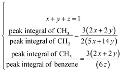 | (1) |
where x, y, and z are molar fractions of heptane, hexadecane, and benzene respectively. Peak integrals were generated in the NMR analysis software (Mnova, Mestrelab). Receiving side component purities were calculated by solving the set of equations listed above. Only zero heptane and hexadecane exchange trials were considered successful runs. All experiments were repeated for at least three times.
3. Results & discussions
3.1 Characterizations of SILM and hydrogel coated membrane
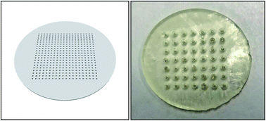
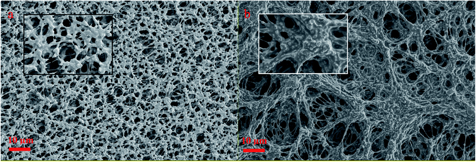
Characterization of the surface morphology of SILM using SEM images shown in Fig. 1 illustrated the distribution of [Bmim][PF6] throughout the entire membrane after 24 hours of impregnation. Fig. 1 shows an example of plain PVDF membranes with 0.65 μm pores and SILMs that are filled with ionic liquids by using the pressure and vacuum method inside a vacuum oven. For the ionic liquid choice used when preparing SILM, [Bmim][PF6] was selected because it showed high selectivity towards benzene/heptane separation.19,23,25
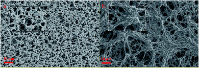 |
| | Fig. 1 The SEM images of supported ionic liquid membranes made from PVDF membranes (0.65 μm pore size) (a) without [Bmim][PF6] (b) impregnated with [Bmim][PF6]. Magnification setting: 1000× (original image) & 5000× (enlarged image). | |
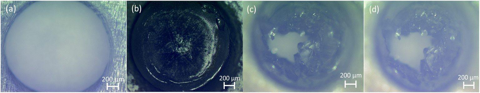
With our integrated membrane boxes, SILMs were used to separate benzene from the initial three-component two-phase mixture and the hydrogel-coated plastic membrane, Fig. 2, was used to separate water from the feed mixture. A layer of hydrogel was coated on 3D-printed plastic membranes through in situ polymerization to realize the separation of immiscible liquid mixtures such as oil and water. The microscope image in Fig. 3(a) shows that the plastic membrane has a pore size of ∼2 mm, which is consistent with the computer-aided sketch. After being coated by hydrogel, the membrane pores were plugged by hydrogel, while they can be “opened” again after the membrane was immersed in water for a week, as shown in Fig. 3(b) and (c). This is because the hydrogel trapped in membrane pores will swell by absorbing water, through which the internal stress of hydrogel builds up and eventually cracks the hydrogel to create the small pore. Fig. 3(d) indicates those cracks were not lost or enlarged even after running 31 cycles of oil–water separation.
 |
| | Fig. 2 A digital model of 3D-printed membrane (left) and 3D-printed plastic membrane coated by zwitterionic hydrogel (right). | |
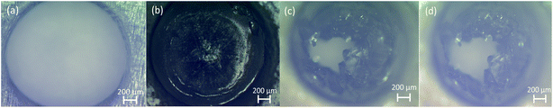 |
| | Fig. 3 Optical microscope images of a pore of (a) bare plastic membrane, (b) hydrogel-coated membrane before water immersion, (c) hydrogel-coated membrane after water immersion and (d) hydrogel-coated membrane after 31 times oil–water separation. Reproduced with permission of the American Chemical Society.21 | |
3.2 3D-printed membrane “box”
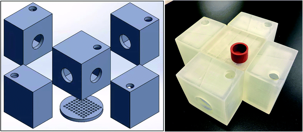
The structure of 3D-printed membrane “box” is shown in Fig. 4. There is a center box where the feed, i.e., benzene (80 mL)/heptane (80 mL)/water (80 mL) mixture, is added. Around the center box there are four receiving box containing the receiving solvent, i.e., hexadecane (120 mL). As shown in Fig. 4, four identical SILMs were sandwiched between the center and the four receiving boxes with Viton rings to clamp them together, respectively, and the hydrogel-coated membrane was mounted on the bottom of the center box.
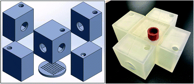 |
| | Fig. 4 The CAD model (left) and the 3D-printed prototype (right) of 1st-design integrated membrane box.21 | |
Oil (i.e., benzene and heptane) and water was separated by the hydrogel-coated hydrophilic/oleophobic membrane at the bottom of the “box”. Water goes through the membrane due to the gravity and the hydrophilicity of the membrane. Oil cannot go through the membrane because the capillary force, which is induced by the oleophobicity of the membrane, is larger than the gravitational force.21 The oil–water separation is complete within 10 minutes and the separation results are summarized in Table 1. The solution going through the hydrogel-coated membrane has a water purity of 99.5% (v), indicating a successful oil–water separation. The reusability of the 3D-printed hydrogel-coated membrane was excellent and additional details on hydrogel-coated membranes are provided in our previous study.21
Table 1 NMR results for oil–water separation with a hydrogel coated membrane in the 3D-printed integrated “box”
| Water separation |
Initial feed volume |
Remaining feed mixture |
Receiving side mixture |
| Benzene |
80 mL |
54.8% |
0.2% |
| Heptane |
80 mL |
44.6% |
0.3% |
| DI water |
80 mL |
0.6% |
99.5% |
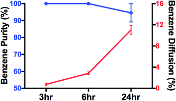
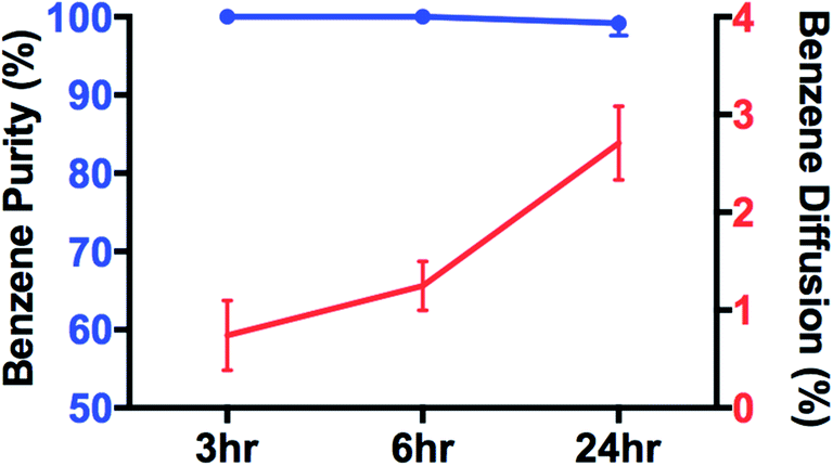
As shown in Fig. 4, benzene was separated from heptane via the SILMs. Since benzene is solvable in [Bmim][PF6] while heptane is not, benzene will go through the SILM and heptane will not. During separation, the benzene in the center box goes through four SILMs to the four receiving boxes. The separation results are shown in Fig. 5. After 24 hours of separation, 2.7% of the initial benzene went through each SILM. Thus, a total of 11 vol% of benzene was withdrawn from the initial benzene in the center box.
 |
| | Fig. 5 Benzene–heptane separation results with each SILM for 3D-printed integrated membrane “box”. | |
3.3 Effect of surface area/volume ratio
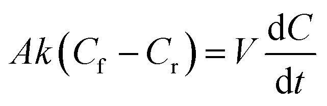
While oil–water separation is reasonably fast, i.e., within 10 minutes, the benzene–heptane separation with SILMs is much slower, i.e., only ∼2.7% of the initial benzene is separated after 24 hours. The benzene throughput  , from the feed to the receiving solution through SILMs can be described by eqn (2) shown below :25
| |
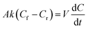 | (2) |
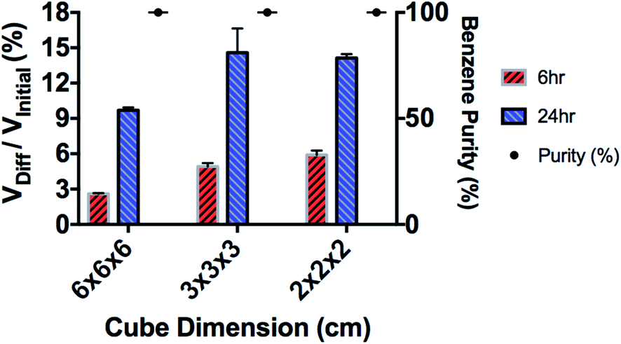
Here A is the surface area of the membrane that is in contact with the solution, k is mass transfer coefficient of the solute, Cf and Cr are concentrations of benzene in the feed solution and in the receiving solution, respectively, V is the volume of the receiving solution, t is time. To increase the separation throughput of SILMs, surface area to volume (A/V) ratio needs to be maximized. To further verify this idea, three types of 3D-printed cubes with different sizes (i.e., A/V ratios), as shown in Fig. 6, were studied. Since A/V is disproportional to the size of the cube, smaller cube is expected to increase the benzene throughput (in percentage of initial benzene volume).
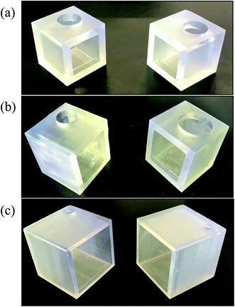 |
| | Fig. 6 3D-printed cubes for surface area/volume ratio experiments (a) 2 × 2 × 2 cm cube (b) 3 × 3 × 3 cm cube (c) 6 × 6 × 6 cm cube. | |
The SILM was sandwiched between two cubes with the same size (see Fig. 6), i.e., one feeding and the other receiving. The separation results are shown in Fig. 7. The benzene throughput after 6 hours increases with the A/V ratio, which conforms our hypothesis. Interestingly, after 24 hours, the benzene throughput was similar for the 3 × 3 × 3 cm cube and 2 × 2 × 2 cm cube, which is ∼1.5 times of that of the 6 × 6 × 6 cm cube. Compare with the clear A/V trend for 6 hour data, a possible reason for losing A/V effects in long-term runs might be due to the drop of concentration gradient which is the driving force of SILM. For a higher A/V ratio, the batch separation completes faster which could be a sign of reaching equilibrium.
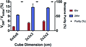 |
| | Fig. 7 Total benzene diffusion across SILM for 6 × 6 × 6 cm cube, 3 × 3 × 3 cm cube, and 2 × 2 × 2 cm cube comparison for 6 hour and 24 hour results. VDiff and VInitial are the benzene volume diffused through SILM and the initial benzene volume in the feed mixture. | |
3.4 Modified 3D-printed membrane “box”
Taking advantage of the idea that smaller cube with higher A/V ratio results in higher benzene throughput, the structure of the membrane “box” was modified. As shown in Fig. 8, the modified “box” consists of three identical separation sectors which hold a maximum capacity of 90 mL initial feed mixture. The SILM is mounted between the neighboring separation sectors. Each separation sector is composed of nine 1.5 × 1.5 × 1.5 cm cubes. The volume of the entire “box” is comparable to that of the center box in the original design. For the modified membrane “box”, each feed side within a separation sector contains equal volume of benzene (10 mL), heptane (10 mL), and DI water (10 mL). The attached receiving side located on the back of the neighboring separation sector contains 15 mL of hexadecane. Two separate sectors which only includes a single feed or a single receive was used to sandwich all other separation sectors. When clamping all sectors together as shown in Fig. 8, feed solutions were added into three feed sides from the top of each column. The receiving side solvent, hexadecane, was added to the built-in receiving side from the smaller top holes. A total of three individual systems was tested for benzene diffusion experiments with a left-side feed box, a right-side receiving box, and two center boxes designed to function as both feed and receiving side for separation across SILM. Viton sheets were used to sandwich each SILM to provide supporting functions. The hydrogel-coated membrane was “built-in” on the bottom of each separation sector. The hydrogel coating procedure is the same as described in Section 2.4. In this design, all centerpieces (i.e., separation sectors) were identical and includes both feeding and receiving functions. As a result, it can expand easily by adding more separation sectors.
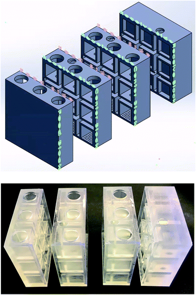 |
| | Fig. 8 Cross section view of the CAD model (top) and the 3D-printed prototype (bottom) of 2nd-design integrated membrane box. | |
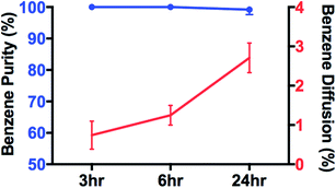
The separation results are shown in Fig. 9. More than 11 vol% of benzene is separated through each separation sector after 24 hours of separation, which is significantly higher than ∼2.7% (Fig. 9) in the original “box”. These results demonstrate that the higher A/V ratio increases the benzene throughput, which is consistent with previous reports.26–29 The purity of benzene (benzene/(benzene + heptane)) in the receiving solution was ∼100% up to 6 hours of separation. After 24 hours of separation, it maintained at ∼95 vol%, which indicates a small amount of heptane also diffused through SILM. This could result from the loss of ionic liquids. After 24 hours of separation, for both original and modified “box”, the benzene throughout is ∼11% of the initial feed benzene. However, the modified “box” has much lower volume, needs less SILM and is easier to scale up. These advantages result from the smaller cube with higher A/V ratio. Oil–water separation results for the modified 3D-printed membrane box is summarized in Table 2. Hydrogel coated membrane built in at the bottom of the membrane box remain efficient for oil–water separation.
 |
| | Fig. 9 Benzene and heptane diffusion across SILM for modified 3D-printed integrated membrane “box”. | |
Table 2 NMR results for oil–water separation with a hydrogel coated membrane in the modified 3D-printed integrated “box”
| Water separation |
Initial feed volume |
Remaining feed mixture |
Receiving side mixture |
| Benzene |
10 mL |
51.9% |
0.0% |
| Heptane |
10 mL |
46.3% |
0.0% |
| DI water |
10 mL |
1.8% |
100% |
Our results highlight the potential of 3D-printed integrated membrane system with multiple selectivity in separating multicomponent and multiphase liquid mixture. Although we only tested the device on a three-component and two-phase mixture (benzene/heptane/water), this approach can be extended to other on-demand multicomponent and multiphase liquid mixtures with modified and complex 3D-printing designs. Compared to conventional multi-step separation process, the novel prototype of a 3D-printed integrated device is more compact, energy-efficient, cost-efficient, and produces less wastes. Moving forward, the major challenge for industry application is still the relatively slow SILM separation. The solution could be a high A/V ratio via geometry optimization plus a continuous flow process to enhance the reliability and feasibility of the device. The 3D-printing approach could also apply to the bio-separation field to address the advanced purification challenges.
4. Conclusion
To conclude, a benzene/heptane/water mixture has been successfully separated using a 3D-printed integrated membrane, which contains supported ionic liquid membranes and a hydrogel-coated hydrophilic/oleophobic membrane. The separation results highlighted the ability of the 3D-printed integrated membrane in separating a multi-component and multi-phase liquid mixture. Our results also showed that the separation throughput can be increased significantly by increasing the total surface area of the SILM.
Abbreviations
| CAD | Computer-aided design |
| NMR | Nuclear magnetic resonance |
| PVDF | Polyvinylidene fluoride |
| SEM | Scanning electron microscope |
| SILM | Supported ionic liquid membrane |
| SLA | Stereolithography |
| TGA | Thermogravimetric analysis |
| [Bmim][PF6] | 1-Butyl-3-methylimidazolium Hexafluorophosphate |
Conflicts of interest
There are no conflicts to declare.
Acknowledgements
This material is based upon work supported by the U.S. Department of Energy's Office of Energy Efficiency and Renewable Energy (EERE) under the Advanced Manufacturing Office Award Number DE-EE0007888.
References
- M. Cheryan and N. Rajagopalan, Membrane processing of oily streams. Wastewater treatment and waste reduction, J. Membr. Sci., 1998, 151(1), 13–28 CrossRef CAS.
- M. Padaki, et al., Membrane technology enhancement in oil–water separation. A review, Desalination, 2015, 357, 197–207 CrossRef CAS.
- S. Munirasu, M. A. Haija and F. Banat, Use of membrane technology for oil field and refinery produced water treatment—A review, Process Saf. Environ. Prot., 2016, 100, 183–202 CrossRef CAS.
- J. Dickhout, et al., Produced water treatment by membranes: A review from a colloidal perspective, J. Colloid Interface Sci., 2017, 487, 523–534 CrossRef CAS PubMed.
- I. Rodríguez-Donis, V. Gerbaud and X. Joulia, Entrainer Selection Rules for the Separation of Azeotropic and Close-Boiling-Temperature Mixtures by Homogeneous Batch Distillation Process, Ind. Eng. Chem. Res., 2001, 40(12), 2729–2741 CrossRef.
- V. Gerbaud, et al., Review of extractive distillation. Process design, operation, optimization and control, Chem. Eng. Res. Des., 2019, 141, 229–271 CrossRef CAS.
- A. B. Pereiro, et al., Ionic liquids in separations of azeotropic systems – A review, J. Chem. Thermodyn., 2012, 46, 2–28 CrossRef CAS.
- L. C. Branco, J. G. Crespo and C. A. M. Afonso, Highly Selective Transport of Organic Compounds by Using Supported Liquid Membranes Based on Ionic Liquids, Angew. Chem., Int. Ed., 2002, 41(15), 2771–2773 CrossRef CAS PubMed.
- J. D. Thornton, Science and practice of liquid-liquid extraction, Oxford science publications, Oxford, 1992, Clarendon Press Search PubMed.
- I. Pinnau and B. D. Freeman, Formation and Modification of Polymeric Membranes: Overview, in Membrane Formation and Modification, 1999, American Chemical Society, pp. 1–22 Search PubMed.
- D. S. Sholl and R. P. Lively, Seven chemical separations to change the world, Nature, 2016, 532(7600), 435–437 CrossRef PubMed.
- J. Yang, et al., Superhydrophilic–superoleophobic coatings, J. Mater. Chem., 2012, 22(7), 2834–2837 RSC.
- A. K. Kota, et al., Hygro-responsive membranes for effective oil-water separation, Nat. Commun., 2012, 3, 1025 CrossRef PubMed.
- J. A. Howarter and J. P. Youngblood, Amphiphile grafted membranes for the separation of oil-in-water dispersions, J. Colloid Interface Sci., 2009, 329(1), 127–132 CrossRef CAS PubMed.
- P. Brown, O. Atkinson and J. Badyal, Ultrafast oleophobic-hydrophilic switching surfaces for antifogging, self-cleaning, and oil-water separation, ACS Appl. Mater. Interfaces, 2014, 6(10), 7504–7511 CrossRef CAS PubMed.
- P. S. Brown and B. Bhushan, Mechanically durable, superoleophobic coatings prepared by layer-by-layer technique for anti-smudge and oil-water separation, Sci. Rep., 2015, 5, 8701 CrossRef PubMed.
- R. Egashira, et al., A Simple Way for the Improvement of Separation Selectivity of Hydrocarbons by O/W/O Emulsion Liquid Membrane, J. Chem. Eng. Jpn., 1995, 28(1), 38–45 CrossRef CAS.
- N. Yamanouchi, A. Ito and K. Yamagiwa, Separation of Benzene/Cyclohexane by Vapor Permeation through Triethylene Glycol Liquid Membrane, J. Chem. Eng. Jpn., 2003, 36(9), 1070–1075 CrossRef CAS.
- M. Matsumoto, Y. Inomoto and K. Kondo, Selective separation of aromatic hydrocarbons through supported liquid membranes based on ionic liquids, J. Membr. Sci., 2005, 246(1), 77–81 CrossRef CAS.
- I. Domínguez, et al., Separation of Benzene from Heptane Using Tree Ionic Liquids: BMimMSO4, BMimNTf2, and PMimNTf2, Procedia Eng., 2012, 42, 1597–1605 CrossRef.
- Y. Song, et al., 3D-Printed Membranes with a Zwitterionic Hydrogel Coating for More Robust Oil–Water Separation, Ind. Eng. Chem. Res., 2020, 59(48), 21058–21065 CrossRef CAS.
- R. Salas, 3D printing for the rapid prototyping of structural electronics, ProQuest Dissertations Publishing, 2013 Search PubMed.
- A. P. de los Ríos, et al., On the importance of the nature of the ionic liquids in the selective simultaneous separation of the substrates and products of a transesterification reaction through supported ionic liquid membranes, J. Membr. Sci., 2008, 307(2), 233–238 CrossRef.
- F. J. Hernández-Fernández, et al., Preparation of supported ionic liquid membranes: Influence of the ionic liquid immobilization method on their operational stability, J. Membr. Sci., 2009, 341(1), 172–177 CrossRef.
- M. Kamaz, et al., π Electron induced separation of organic compounds using supported ionic liquid membranes, Sep. Purif. Technol., 2020, 236, 116237 CrossRef CAS.
- F. Eisenhaber, et al., The double cubic lattice method: Efficient approaches to numerical integration of surface area and volume and to dot surface contouring of molecular assemblies, J. Comput. Chem., 1995, 16(3), 273–284 CrossRef CAS.
- V. Thavasi, G. Singh and S. Ramakrishna, Electrospun nanofibers in energy and environmental applications, Energy Environ. Sci., 2008, 1(2), 205 RSC.
- L. J. Lozano, et al., Recent advances in supported ionic liquid membrane technology, J. Membr. Sci., 2011, 376(1), 1–14 CrossRef CAS.
- A. K. Pabby, B. Swain and A. M. Sastre, Recent advances in smart integrated membrane assisted liquid extraction technology, Chem. Eng. Process., 2017, 120, 27–56 CrossRef CAS.
|
| This journal is © The Royal Society of Chemistry 2021 |
Click here to see how this site uses Cookies. View our privacy policy here. 
 Open Access Article
 This Open Access Article is licensed under a Creative Commons Attribution-Non Commercial 3.0 Unported Licence
 ,
Bingchen Wang
,
Bingchen Wang

 , from the feed to the receiving solution through SILMs can be described by eqn (2) shown below :25