 Open Access Article
Creative Commons Attribution 3.0 Unported Licence
Tailoring spintronic and opto-electronic characteristics of bilayer AlN through MnOx clusters intercalation; an ab initio study
Irfan Ahmeda,
Yong Shuaib,
Muhammad Rafique *ab,
Mukhtiar Ahmed Maharac and
Abdul Sattar Larikac
aMehran University of Engineering and Technology, SZAB, Campus, Khairpur Mirs', Pakistan
bSchool of Energy Science and Engineering, Harbin Institute of Technology, 92 West Dazhi Street, Harbin, 150001, PR China. E-mail: rafique@hit.edu.cn; shuaiyong@hit.edu.cn
cMehran University of Engineering and Technology, Jamshoro, Sindh, Pakistan
First published on 22nd April 2021
Abstract
Adopting ab initio density functional theory (DFT) technique, the spintronic and opto-electronic characteristics of MnOx (i.e., Mn, MnO, MnO2, MnO3 and MnO4) clusters intercalated bilayer AlN (BL/AlN) systems are investigated in this paper. In terms of electron transfer, charge transfer occurs from BL/AlN to the MnOx clusters. MnOx clusters intercalation induces magnetic behavior in the non-magnetic AlN system. The splitting of electronic bands occurs, thus producing spintronic trends in the electronic structure of BL/AlN system. Further, MnOx intercalation converts insulating BL/AlN to a half metal/semiconductor material during spin up/down bands depending upon the type of impurity cluster present in its lattice. For instance, Mn, MnO and MnO2 intercalation in BL/AlN produces a half metallic BL/AlN system as surface states are available at the Fermi Energy (EF) level for spin up and down band channels, accordingly. Whereas, MnO3 and MnO4 intercalation produces a conducting BL/AlN system having a 0.5 eV and 0.6 eV band gap during the spin down band channel, respectively. During spin up band channels these systems behave as semiconductors with band gaps of 1.4 eV and 1.2 eV, respectively. In terms of optical characteristics (i.e., absorption coefficient, reflectivity and energy loss spectrum (ELS)), it was found that MnOx intercalation improves the absorption spectrum in the low electron energy range and absorption peaks are observed in the 0–3 eV energy range, which are not present in the absorption spectrum of pure BL/AlN. The static reflectivity parameter of BL/AlN is increased after MnOx intercalation and the ELS parameter obtains significant peak intensities in the 0–2 eV energy range, whereas for pure BL/AlN, ELS contains negligible value in this energy range. Outcomes of this study indicate that, MnOx clusters intercalation in BL/AlN is a suitable technique to tailor its spintronic and opto-electronic trends. Thus, experimental investigation can be carried out on the systems discussed in this work, so as to fabricate practical layered AlN systems that are functional in the field of nano-technology.
1. Introduction
Successful extraction of monatomic two-dimensional (2D) graphene in 2004,1 ignited the scientific community to discover more about 2D materials. As a result, various monatomic 2D materials such as, h-BN,2 MoS2,3 SiC4 and ZnO5 were studied and analyzed experimentally in their monatomic state. These materials were further adopted and investigated for their layered configurations, such as bilayer and few-layer graphene6 and h-BN material7–9 in order to make them functional for nano-device applications. Further into the 2D materials family, group III-Nitride 2D materials carry significant potential for their use as state of the art solid state devices, sensors/actuators and visible range photo-catalysis process.10–13 Among these group III-Nitrides, monatomic AlN with a 3.92 eV band gap14 offers promising applications as a DMS (dilute magnetic semiconductor). Theoretical investigations based on DFT technique carried out on the DMS behavior of the monatomic AlN layer indicated that, proper/selective substitution of transition metal (TM) atoms in the AlN layer can make it display ferromagnetic behavior above room temperature.15–18 Electronic properties of AlN nanotubes and nanowires were studied by Zhou et al.,19 and the authors suggested AlN nano-tubes and wires can be utilized for ammonia sensing applications. Similarly, nano-ribbons of pristine AlN were synthesized by Xie et al.20 using a chloride-assisted-vapor-solid-route technique.From aforementioned studies it can be realized that, significant work is already being performed on monolayer and nano-tubes of AlN system. However, bilayer or multilayered AlN systems are slightly studied. Consequently, conception of interlayer interference and the properties of layered AlN systems is a thought to discover and it can produce appealing progress in the field of layered AlN systems. Earlier, significant efforts have been carried out to understand the structural, electronic and energetic of single and multi-layered h-BN systems.21–26 Various concepts to be understood for multi-layered systems include, Moiré patterns upon relative rotation of few layers27,28 and observations of displacement in stacked layers.29–31 Experimental studies carried out on impurity clusters intercalated layered graphene systems,32–34 suggest that, foreign intercalated impurities can significantly modify the opto-electronic and magnetic parameters of layered systems. Similarly, T. Kaneko et al.35 carried out first-principles investigation on alkali and alkaline earth metal intercalated bilayer graphene systems, indicating that these intercalated atoms can greatly modify its energetic and conductivity parameters. In addition, very recently, studies have been carried out on layered 2D materials having defective configurations.36–40 These, theoretical and experimental studies conclude that physical parameters of layered 2D systems can greatly be modified through intercalation technique. All the earlier studies carried out on layered 2D systems suggest that, electronic, magnetic and optical behaviors of these stacked systems can be manipulated by modifying their stacking position. Though, another suitable approach to adapt these parameters is through chemical doping process. Impurity atoms/clusters can be substituted or intercalated in the layered systems, thus producing a hybrid material. For instance, experimental studies were performed on impurity clusters intercalated few layered graphene systems.32–34 Outcomes of these studies revealed that, foreign impurities when doped/intercalated into layered systems can easily alter the electronic, magnetic and optical parameters of layered 2D systems as compared to their pristine counterparts. Likewise, H. Jinsen et al.41 performed ab initio DFT calculations on TM atoms intercalated bilayer graphene and it was found that, TM intercalation in bilayer graphene can produce a stable 2D magnetic substrate. Few studies carried out on twisted/defective h-BN layers42–45 suggest that, homo/hetero/defective layers can produce functional layered materials for nano-electronic and energy storage applications.
Since, significant amount of work has been dedicated to few layered graphene and h-BN systems, so this concept can be elongated for AlN layers, in order to obtain a functional layered AlN system. Akin to monatomic AlN, bilayer (BL)/AlN is also an insulating material, with non-magnetic nature and behaves opaquely in the visible range of spectrum.7 Since, BL/AlN is a wide band insulator; hence it cannot be utilized in fields of energy storage or smart generation applications. So as to make it functional for energy storage, optoelectronic and spintronic device applications, it is essential to modify its physical behaviors first. In order to gain aforementioned objectives, MnOx clusters were adopted as impurities and were intercalated in BL/AlN system. The effect of MnOx intercalation on the structural, electronic, magnetic and optical properties of BL/AlN systems was investigated in detailed manner. MnOx clusters were adopted as intercalation agents owing to their excess of charge and easy transport nature. MnOx clusters can behave as n-type or p-type impurities, depending upon the layered configurations; thereby manipulating the band gap in the electronic structure of BL/AlN system. It is well known fact that, optical transitions are linked to the inter/intra band transitions occurring in the electronic structures, hence modifying band gap will directly affect the optical behaviors of BL/AlN system. Furthermore, regarding magnetic behavior, it can be proposed that the unfilled d orbitals of Mn atom can produce significant spin variation in the BL/AlN, thus producing a magnetic bilayer substrate. As stated in earlier studies that, the halogen and super halogen i.e., TMO3 and TMO4 clusters can greatly modify the physical parameters of monolayer graphene46,47 and h-BN48 systems. Hence, we try to extend this notion to BL/AlN systems. Up to our knowledge, such complex systems of AlN material have been lightly touched and comprehension of these systems remains partial and scattered. Obtained outcomes of this work can provide a subtle path for tailoring spintronic and opto-electronic trends of BL/AlN systems to be functional for nano-electronic devices, distinctive to those of pristine monolayer AlN systems.
2. Computational details and geometry models
Adopting ab initio DFT calculations in Generalized Gradient Approximation (GGA)49–51 implemented in Vienna Ab initio Simulation Package (VASP version 5.2.2),52–54 the electronic, magnetic and optical behaviors of MnOx (i.e., Mn, MnO, MnO2, MnO3 and MnO4) intercalated BL/AlN were studied in detail. A 4 × 3 supercell structure was adopted for Bilayer AlN (BL/AlN)55,56 and the computations were carried out through plane-wave basis set with ultrasoft psuedopotentials52,57 having 450 eV cut-off energy. All computations were performed in spin polarized mode. Grimme (DFT-D2)49 method was utilized for van der Waals (vdW) corrections due to the long-range vdW interactions in between layers.58–60 A 15 Å vacuum thickness was added along the Z-direction so as to reduce the interference problem between adjacent layers.55,61,62 Larger vacuum thickness size supports omission of interlayer interference. In order to gain satisfactory convergence in the DFT results, a fine 17 × 17 × 1 k-point mesh was employed. Geometry relaxation was performed till the Hellmann–Feynman forces were up to 0.03 eV Å−1 value and variation in total energy step less than 10−6 eV was not achieved. Gaussian smearing was implemented in order to deal with partial occupancy problem. Normal and in-plane views of relaxed geometry of pristine 4 × 3 BL/AlN system are presented in Fig. 1(a) and (b), in that order. The terms and
and  correspond to the vector quantities of AlN unit cell in the figures given below.
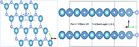 | ||
| Fig. 1 Illustration for atomic structure of 4 × 3 BL/AlN system (a) normal and (b) in-plane view of optimized geometry of BL/AlN system. | ||
In order to calculate fine grid electronic properties, 30 K-points were adapted for Γ − M − K − Γ path in the irreducible Brillouin zone (IBZ). For calculating partial/local and total density of states of MnOx intercalated BL/AlN systems, 17 × 17 × 1 k-points were utilized and a 0.03 eV Gaussians width was employed for eigenvalues smearing. Total/partial DOS on constituents of AlN system and intercalated impurities were determined in spin polarized mode. Subjected to the band gap sensitivity problem, we investigated both the Local Density Approximation (LDA) and Perdew–Burke–Ernzerhof exchange-correlation (PBE) functionals, subsequently, it was observed that the functional choice did not produce larger band gap variation and a slight variation of ∼0.02 eV was observed in the band gap.
Likewise, for optical properties, DFT within Random Phase Approximations (RPA)63 technique was implemented. The imaginary part of dielectric constant was obtained through summation of empty states, as described. In eqn (1), α and β are Cartesian vectors, eα/eβ are primal vectors and the c/v parameters depict conduction and valence bands, respectively. The terms ∈ck/∈vk respond to the corresponding energy of c/v bands, cell periodic part at a given point k is denoted uck term.
 | (1) |
The real part of dielectric constant can be obtained through Kramers–Kronig transformation as described. Here P parameter depicts Principal value.63
 | (2) |
Obtained real (ε′) and imaginary (ε′′) parts of dielectric constant can be utilized for extracting total dielectric constant by ε = ε′ + ε′′ together.63 Later on, optical absorption ‘α’ and reflectivity ‘R’, real and imaginary refractive index i.e., ‘n’ and ‘k’ parameters can be determined through dielectric constant, as explained in detail in earlier reports.64,65 For aforementioned optical properties, focus of our work is directed towards lower energy i.e., 0–12 eV energy range. Our main goal is to modify the absorption spectrum of bilayer AlN system in visible range, along with its static reflectivity by MnOx intercalation. MnOx intercalated BL/AlN systems with modified optical properties in the visible region can be a viable candidate for opto-electronic applications as compared to its single layer counterpart.
3. Results and discussions
Outcomes of this study along with their relevant analysis are provided as follows;3.1 Structural properties of MnOx intercalated BL/AlN
Structural diagrams of bilayer AlN system intercalated with MnOx (i.e., Mn, MnO, MnO2, MnO3 and MnO4) clusters are presented in Fig. 2(a)–(e), respectively. When MnOx clusters are intercalated in BL/AlN, these clusters try to hold their position at the center of interlayer space as visible in Fig. 2(a) and (b). However, after MnOx cluster intercalation, the bond lengths of N–Al atoms of both layers available in the vicinity of impurities get distorted. Thus a variation in range of 1.44–1.47 Å in N–Al bond lengths is obtained in both AlN layers. Bond length variation observed in N–Al atoms is totally dependent on the type of MnOx cluster available in the interlayer space as visible in Fig. 2(a)–(e), respectively. A change in the interlayer distance was also observed ranging in between 3.10–3.18 Å, again totally dependent on the type of MnOx cluster intercalated in BL/AlN. These outcomes are consistent with earlier reports.66,67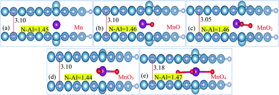 | ||
| Fig. 2 (a)–(e) Atomic Structure of MnOx cluster intercalated bilayer AlN systems (side view), showing N–Al bond length and interlayer distance in Å, accordingly. | ||
Total magnetic moment of various MnOx cluster intercalated BL/AlN systems, magnetic moments of Mn atom and the equatorial bond distances of N–Al, Mn–O and interlayer distance for that particular complex systems are enlisted in Table 1, in that order. Presented accumulative magnetic moments of various MnOx cluster intercalated BL/AlN systems depict that, MnOx clusters significantly improve the ferromagnetic behavior in BL/AlN as evident by their larger values of magnetic moments, respectively.46,68 Some earlier studies carried out on magnetism of 2D materials have suggested the same behaviors.69–71 Further, it becomes necessary to determine first whether the given MnOx cluster intercalated BL/AlN systems are thermodynamically stable or not, binding energy of each system should be calculated first. Binding energies for given systems can be calculated using following expression66 and are enlisted in Table 1,
| Eb = E(AlN+MnOx) − (2E(AlN) + EMnOx) | (3) |
| Impurity | μtot, in μB | μMN, in μB | dN–Al Å | dMn-O Å | dAlN–AlN Å | Eb (eV) |
|---|---|---|---|---|---|---|
| Mn | 3.7 | 2.835 | 1.45 | 2.10 | 3.10 | 2.99 |
| MnO | 2.76 | 1.58 | 1.46 | 1.98 | 3.10 | 3.01 |
| MnO2 | 3.01 | 2.51 | 1.46 | 2.11 | 3.05 | 3.36 |
| MnO3 | 1.03 | 0.96 | 1.44 | 1.95 | 3.10 | 3.72 |
| MnO4 | 1.12 | 0.93 | 1.47 | 1.98 | 3.18 | 4.48 |
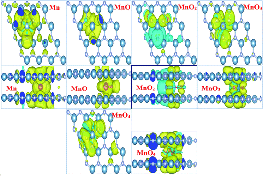
Fig. 3 illustrates the spin density of all the MnOx cluster-intercalated bilayer AlN systems. Given Fig. 3 clearly defines that the intercalated MnOx clusters create magnetic behavior in non-magnetic N and Al atoms of AlN layer lying above and below the impurity clusters. In addition, spin density created in the bilayer AlN layer is not localized rather it is distributed throughout the bilayer plane as visible in the top view of spin density diagrams. Almost all the MnOx clusters and AlN layers attain anti-parallel spin polarization direction as visible in the side view of spin difference diagrams. However, only in case of MnO2 intercalation parallel spin polarization is observed in between impurity cluster and Bilayer AlN. Main attribution towards magnetism is by the unfilled d-orbital electrons of Mn atoms carrying clockwise spin direction as evident by yellow isosurface (0.002 e Å−3), for all given MnOx clusters except MnO2 cluster. Similarly, parallel spin polarization was observed between Mn and O atoms except MnO cluster-incorporated BL/AlN, which carried antiparallel spin polarization as shown in Fig. 3, respectively. These observations are persistent with earlier reports.66,73,74
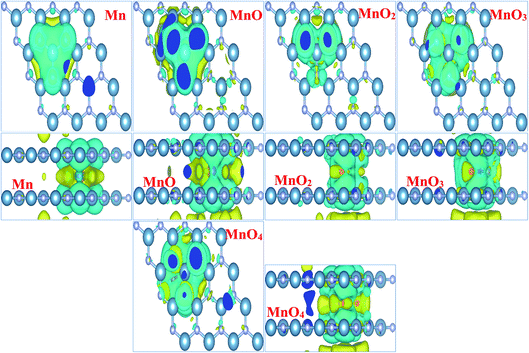
In order to totally comprehend the electronic interaction of MnOx clusters with BL/AlN systems, we investigated charge difference and transfer behavior of all MnOx cluster-incorporated BL/AlN systems through Bader analysis.75,76 The charge difference can be obtained by Δρ = ρMnOx-BL/AlN − ρBL/AlN − ρMnOx. Where ρMnOx-BL/AlN, ρBL/AlN and ρMnOx display charge density of MnOx cluster-intercalated BL/AlN, charge density of AlN layers and the charge density of MnOx clusters, in that order. Obtained charge difference diagrams for all MnOx cluster-intercalated BL/AlN systems are offered in Fig. 4, respectively. The yellow (0.0001 e Å−3) and cyan isosurfaces (0.0001 e Å−3) display the occurrence of electron gain and loss behavior between MnOx clusters and BL/AlN, respectively. Illustrated charge difference diagrams of MnOx cluster-intercalated BL/AlN complexes carry similar charge transfer phenomenon i.e., AlN layer lose their charge to electronegative MnOx clusters as these clusters carry larger chunk of yellow isosurface while AlN layer are covered by cyan isosurface thus indicating charge transfer direction from AlN layers to MnOx clusters, respectively. As bilayer AlN systems display electron loss behavior thus MnOx intercalation can be considered as “Hole” doping process. These predictions are in consensus with earlier published reports.77–80
3.2 Electronic structures of MnOx cluster-intercalated BL/AlN
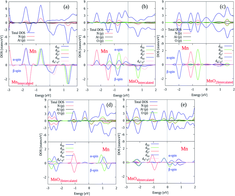
In this section, the spin polarized electronic structures and density of states (DOS) plots of pure and MnOx cluster (i.e., Mn, MnO, MnO2, MnO3 and MnO4) intercalated bilayer AlN complex were analyzed in detail and are illustrated in Fig. 5(a)–(f), respectively. Fermi Energy level (EF) is shown by purple color dotted line drawn at 0 eV energy in given diagrams. As a reference, the band structure of pure BL/AlN is added as shown in Fig. 5(a) and our obtained work is consistent with these reports,81–83 which indicates that our computational method is accurate enough to carry out further calculations in this regard. Band gap value of BL/AlN was found as ∼3.92 eV which agrees well with earlier cited reports. After MnOx intercalation in BL/AlN significant change is observed in its electronic structure. Mn, MnO and MnO2 intercalation in BL/AlN converts wide band BL/AlN to a half metallic material for both spin up and down bands respectively, as some energy bands appear at the EF level as shown in Fig. 5(b)–(d), in that order. However, during MnO3 and MnO4 intercalation, wide band BL/AlN is converted to narrow band semiconducting material for both spin up and down channels as shown in Fig. 5(e)–(f), respectively. Obtained band gap during MnO3 intercalation is found to be 1.2 eV and 0.4 eV, during spin up and spin down band channels, as shown in Fig. 5(e), respectively. Similarly, band gap obtained through MnO4 intercalation was 1.3 eV and 0.5 eV, during spin up and spin down band channels, as shown in Fig. 5(f), respectively. As per above discussion, it can be presumed that, MnOx intercalation can be a suitable technique to modify electronic structures of BL/AlN systems. Given results are in consensus with previous literature.84–86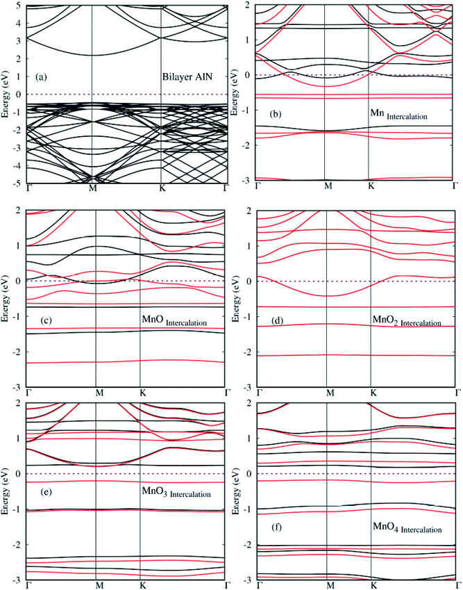 | ||
| Fig. 5 (a)–(f) Spin polarized electronic structures for MnOx cluster-intercalated BL/AlN (4 × 3) supercell structures. Black and Red lines depict spin up and spin down bands, respectively. | ||
After electronic structures, the partial and local (P/L DOS) plots for all MnOx cluster-incorporated BL/AlN systems are investigated, so that the orbital interaction between impurity cluster atoms and BL/AlN can be analyzed. P/L-DOS on d orbitals of Mn atoms and constituent Al, N and O atoms of MnOx BL/AlN were calculated and are produced in Fig. 6(a)–(d), respectively. The EF level is depicted at 0 eV energy drawn by vertical grey line in given P/L-DOS plots. As mentioned in Table 1, all the MnOx intercalated BL/AlN systems carried definite magnetic moments; hence the d orbitals of Mn atom and the sp orbitals of N, Al and O atoms carried spin polarization thus creating variation in band gap value for spin up and down bands as clearly depicted in Fig. 6(a) and (d), respectively. From the given band structure and DOS plots of MnOx intercalated BL/AlN systems it can be generalized that, MnOx intercalation in BL/AlN not only tunes the band gap parameter but can convert it to DMS material. Since these systems carry finite magnetic moments and differing band gap values during spin up and down channels. These astonishing properties of MnOx intercalated BL/AlN systems can make it practical choice for spintronic devices.
3.3 Optical properties of MnOx cluster-intercalated BL/AlN
Lastly, we calculate the optical characteristics of MnOx clusters (i.e., Mn, MnO, MnO2, MnO3 and MnO4) intercalated BL/AlN systems through RPA-DFT.63 In RPA-DFT Local field effects are omitted while inter/intra band transitions are considered, thus inaccuracies can be expected in dielectric constant at lower energies. A fine 11 × 11 × 1 Γ-centered BZ sampling is adopted for optical properties calculations.Absorption ‘α’, reflectivity ‘R’ and energy loss spectrum ‘ELS’ parameters can easily be calculated through dielectric constant as elaborated in ref. 64. The absorption coefficient of pure and various MnOx clusters intercalated BL/AlN systems are illustrated in Fig. 7(a). Our main focus is dedicated to tailoring optical parameter of BL/AlN in lower energy i.e., 0–12 eV range. The absorption spectrum of pure BL/AlN has no absorption peaks up to 3 eV energy layer as visible in Fig. 7(a). However, after MnOx intercalation, absorption coefficient starts to rise from 0 eV energy. As seen, MnO and MnO2 intercalation produces absorption intensity of 1000 cm−1 and 2000 cm−1 at 0.75 eV and 3.5 eV energy points which were not available in case of pure BL/AlN system. In addition, MnOx intercalation overall improves the absorption spectrum of BL/AlN in lower energy as obvious in Fig. 3(a).87,88
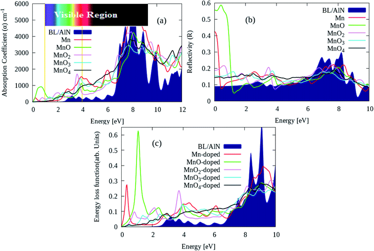 | ||
| Fig. 7 (a) Absorption coefficient ‘α’, (b) reflectivity ‘R’ and (c) ELS parameters of pure and MnOx clusters intercalated BL/AlN systems, respectively. | ||
Likewise, the ‘R’ parameter of aforementioned systems is provided in Fig. 7(b). MnOx intercalation improves static ‘R’ parameter of BL/AlN system having 0.58 maximum peak intensity of MnO intercalated BL/AlN system as revealed in Fig. 7(b). Lastly, ELS parameter of pure and MnOx cluster-intercalated BL/AlN systems is shown in Fig. 7(c). It can be observed that, MnOx clusters provide larger energy variation to the electrons of BL/AlN system in between 0–2 eV energy as noticeable in Fig. 7(c), accordingly.88,89 In general, it can be presumed that, MnOx cluster intercalation in BL/AlN can significantly improve its optical parameters in low electron energy range thus making it functional for opto-electronic device applications. From given MnOx cluster intercalated in BL/AlN systems, comparatively it can be suggested that MnO-intercalated BL/AlN system bears suitable optical parameters thus, this model can be realized for experimental studies.
4. Conclusion
In this study, we analyzed various MnOx clusters (i.e., Mn, MnO, MnO2, MnO3 and MnO4) intercalated BL/AlN systems through FPS-DFT technique. As MnOx clusters offer higher electronegative nature, thus stable BL/AlN systems containing MnOx clusters as impurities can be realized as obvious through obtained positive binding energy values for all systems. Spin difference diagrams of given systems clearly suggest that magnetic BL/AlN systems can be generated through MnOx clusters intercalation. Magnetic moments for Mn, MnO, MnO2, MnO3 and MnO4 intercalated BL/AlN systems were obtained as 3.7 μB, 2.76 μB, 3.01 μB, 1.03 μB and 1.12 μB, respectively. Through charge transfer diagrams it is revealed that, the charge transfer occurs from BL/AlN to MnOx clusters, hence creating hole doping process in BL/ALN system.Through calculated spin polarized band structures, it was observed that the MnOx clusters intercalation in BL/AlN, the wide band insulating BL/AlN can be converted to half metal/semiconductor depending upon the type of intercalated MnOx cluster. Through Mn, MnO and MnO2 intercalation half metallic BL/AlN system is achieved for both spin up and down bands respectively. For MnO3 and MnO4 intercalation, wide band BL/AlN is converted to narrow band semiconducting material for both spin up and down channels. Obtained band gap during MnO3 intercalation is found to be 1.2 eV and 0.4 eV, during spin up and spin down band channels, respectively. Whereas, band gap obtained through MnO4 intercalation was 1.3 eV and 0.5 eV, during spin up and spin down band channels, respectively. In addition, through PDOS analysis it is revealed that, the intercalated systems having finite magnetic moments exhibit orbital polarization phenomenon. It is also presumed that the d orbitals (i.e. dxy, dyz, dz2, dxz and dx2–y2) of Mn atom are mainly contribute to the obtained magnetic behavior of BL/AlN system. Thus suggesting functionality of studied systems in spintronic devices.
Finally, through optics properties, it is observed that the ‘α’ and ‘R’ and ELS parameters of MnOx intercalated BL/AlN systems achieve significant variation in low electron energy range. In addition, MnOx intercalation introduces red shift to ‘α’ parameter and it is significantly improved in visible region. In general conclusion and through detailed analysis, it can be suggested that MnOx cluster-intercalated BL/AlN systems demonstrate significant potential for being functional for innovative spintronic and optoelectronic applications, which are distinctive to their pristine BL/ALN systems.
Conflicts of interest
There are no conflicts to declare.Acknowledgements
This work was supported by the National Natural Science Foundation of China (No. 51876049) and Higher Education Commission, Pakistan under SRGP (No: 21-1778/SRGP/R&D/HEC/2017).References
- K. S. Novoselov, A. K. Geim, S. V. Morozov, D. Jiang, Y. Zhang, S. V. Dubonos, I. V. Grigorieva and A. A. Firsov, Science, 2004, 306, 666–669 CrossRef CAS PubMed.
- A. R. Phani, Bull. Mater. Sci., 1994, 17, 219–224 CrossRef CAS.
- C. Ataca, H. Sahin, E. Akturk and S. Ciraci, J. Phys. Chem. C, 2011, 115, 3934–3941 CrossRef CAS.
- L. Sun, Y. Li, Z. Li, Q. Li, Z. Zhou, Z. Chen, J. Yang and J. Hou, J. Chem. Phys., 2008, 129, 174114 CrossRef PubMed.
- Q. Wan, Z. Xiong, J. Dai, J. Rao and F. Jiang, Opt. Mater., 2008, 30, 817–821 CrossRef CAS.
- D. Zhan, L. Sun, Z. H. Ni, L. Liu, X. F. Fan, Y. Wang, T. Yu, Y. M. Lam, W. Huang and Z. X. Shen, Adv. Funct. Mater., 2010, 20, 3504–3509 CrossRef CAS.
- A. V. Lebedev, I. V. Lebedeva, A. A. Knizhnik and A. M. Popov, RSC Adv., 2016, 6, 6423–6435 RSC.
- A. Falin, Q. Cai, E. J. Santos, D. Scullion, D. Qian, R. Zhang, Z. Yang, S. Huang, K. Watanabe and T. Taniguchi, Nat. Commun., 2017, 8, 15815 CrossRef CAS PubMed.
- I. V. Lebedeva, A. V. Lebedev, A. M. Popov and A. A. Knizhnik, Phys. Rev. B, 2016, 93, 235414 CrossRef.
- I. Vurgaftman, J. á. Meyer and L. á. Ram-Mohan, J. Appl. Phys., 2001, 89, 5815–5875 CrossRef CAS.
- F. A. Ponce and D. P. Bour, Nature, 1997, 386, 351 CrossRef CAS.
- J. Liao, B. Sa, J. Zhou, R. Ahuja and Z. Sun, J. Phys. Chem. C, 2014, 118, 17594–17599 CrossRef CAS.
- Y. Mei, D. J. Thurmer, C. Deneke, S. Kiravittaya, Y.-F. Chen, A. Dadgar, F. Bertram, B. Bastek, A. Krost, J. Christen, T. Reindl, M. Stoffel, E. Coric and O. G. Schmidt, ACS Nano, 2009, 3, 1663–1668 CrossRef CAS PubMed.
- C.-w. Zhang, J. Appl. Phys., 2012, 111, 043702 CrossRef.
- T. Dietl, H. Ohno, F. Matsukura, J. Cibert and D. Ferrand, Science, 2000, 287, 1019–1022 CrossRef CAS PubMed.
- K. Sato and H. Katayama-Yoshida, Phys. E, 2001, 10, 251–255 CrossRef CAS.
- Q. Wang, Q. Sun, P. Jena and Y. Kawazoe, Phys. Rev. B, 2004, 70, 052408 CrossRef.
- V. Litvinov and V. Dugaev, Phys. Rev. Lett., 2001, 86, 5593 CrossRef CAS PubMed.
- Z. Zhou, J. Zhao, Y. Chen, P. von Ragué Schleyer and Z. Chen, Nanotechnology, 2007, 18, 424023 CrossRef PubMed.
- T. Xie, Y. Lin, G. Wu, X. Yuan, Z. Jiang, C. Ye, G. Meng and L. Zhang, Inorg. Chem. Commun., 2004, 7, 545–547 CrossRef CAS.
- V. Solozhenko, A. Lazarenko, J.-P. Petitet and A. Kanaev, J. Phys. Chem. Solids, 2001, 62, 1331–1334 CrossRef CAS.
- R. Nemanich, S. Solin and R. M. Martin, Phys. Rev. B, 1981, 23, 6348 CrossRef CAS.
- K. Albe, Phys. Rev. B, 1997, 55, 6203 CrossRef CAS.
- G. Kern, G. Kresse and J. Hafner, Phys. Rev. B, 1999, 59, 8551 CrossRef CAS.
- G. Constantinescu, A. Kuc and T. Heine, Phys. Rev. Lett., 2013, 111, 036104 CrossRef PubMed.
- C.-R. Hsing, C. Cheng, J.-P. Chou, C.-M. Chang and C.-M. Wei, New J. Phys., 2014, 16, 113015 CrossRef.
- Z. Y. Rong and P. Kuiper, Phys. Rev. B, 1993, 48, 17427 CrossRef CAS PubMed.
- Y. Gan, W. Chu and L. Qiao, Surf. Sci., 2003, 539, 120–128 CrossRef CAS.
- L. Brown, R. Hovden, P. Huang, M. Wojcik, D. A. Muller and J. Park, Nano Lett., 2012, 12, 1609–1615 CrossRef CAS PubMed.
- P. San-Jose, R. Gorbachev, A. Geim, K. Novoselov and F. Guinea, Nano Lett., 2014, 14, 2052–2057 CrossRef CAS PubMed.
- J. S. Alden, A. W. Tsen, P. Y. Huang, R. Hovden, L. Brown, J. Park, D. A. Muller and P. L. McEuen, Proc. Natl. Acad. Sci. U. S. A., 2013, 110, 11256–11260 CrossRef CAS PubMed.
- N. Kim, K. S. Kim, N. Jung, L. Brus and P. Kim, Nano Lett., 2011, 11, 860–865 CrossRef CAS PubMed.
- M. Dresselhaus and G. Dresselhaus, Adv. Phys., 1981, 30, 139–326 CrossRef CAS.
- K. Ohhashi and I. Tsujikawa, J. Phys. Soc. Jpn., 1974, 36, 422–430 CrossRef CAS.
- T. Kaneko and R. Saito, Surf. Sci., 2017, 665, 1–9 CrossRef CAS.
- S. Wang, C. Ren, H. Tian, J. Yu and M. Sun, Phys. Chem. Chem. Phys., 2018, 20, 13394–13399 RSC.
- C. M. Fung, J. S. Lloyd, S. Samavat, D. Deganello and K. S. Teng, Sens. Actuators, B, 2017, 247, 807–813 CrossRef CAS.
- J. Lloyd, C. Fung, D. Deganello, R. Wang, T. Maffeis, S.-P. Lau and K. S. Teng, Nanotechnology, 2013, 24, 195602 CrossRef CAS PubMed.
- A. K. Assaifan, J. S. Lloyd, S. Samavat, D. Deganello, R. J. Stanton and K. S. Teng, ACS Appl. Mater. Interfaces, 2016, 8, 33802–33810 CrossRef CAS PubMed.
- S. Wang, H. Tian, C. Ren, J. Yu and M. Sun, Sci. Rep., 2018, 8, 12009 CrossRef.
- J. Han, D. Kang and J. Dai, RSC Adv., 2018, 8, 19732–19738 RSC.
- J. Wang, F. Ma, W. Liang and M. Sun, Materials Today Physics, 2017, 2, 6–34 CrossRef.
- J. Wang, X. Xu, X. Mu, F. Ma and M. Sun, Materials Today Physics, 2017, 3, 93–117 CrossRef.
- J. Wang, X. Mu, X. Wang, N. Wang, F. Ma, W. Liang and M. Sun, Materials Today Physics, 2018, 5, 29–57 CrossRef.
- J. Wang, F. Ma and M. Sun, RSC Adv., 2017, 7, 16801–16822 RSC.
- M. Rafique, Y. Shuai, H.-P. Tan and H. Muhammad, Appl. Surf. Sci., 2017, 408, 21–33 CrossRef CAS.
- M. Rafique, Y. Shuai, H.-P. Tan and H. Muhammad, Appl. Surf. Sci., 2017, 399, 20–31 CrossRef CAS.
- R. Muhammad, M. A. Uqaili, Y. Shuai, M. A. Mahar and I. Ahmed, Appl. Surf. Sci., 2018, 458, 145–156 CrossRef CAS.
- S. Grimme, J. Comput. Chem., 2006, 27, 1787–1799 CrossRef CAS PubMed.
- J. P. Perdew, K. Burke and M. Ernzerhof, Phys. Rev. Lett., 1996, 77, 3865 CrossRef CAS PubMed.
- A. A. Peyghan, M. Noei and S. Yourdkhani, Superlattices Microstruct., 2013, 59, 115–122 CrossRef CAS.
- G. Kresse and D. Joubert, Phys. Rev. B, 1999, 59, 1758 CrossRef CAS.
- G. Kresse and J. Furthmüller, Comput. Mater. Sci., 1996, 6, 15–50 CrossRef CAS.
- G. Wang, A. K. F. Rahman and B. Wang, J. Mol. Model., 2018, 24, 116 CrossRef PubMed.
- R. Muhammad, Y. Shuai and H.-P. Tan, J. Mater. Chem. C, 2017, 5, 8112–8127 RSC.
- M. Rafique, Y. Shuai, H.-P. Tan and M. Hassan, RSC Adv., 2017, 7, 16360–16370 RSC.
- G. Kresse and J. Hafner, J. Phys.: Condens. Matter, 1994, 6, 8245 CrossRef CAS.
- S. Grimme, C. Mück-Lichtenfeld and J. Antony, J. Phys. Chem. C, 2007, 111, 11199–11207 CrossRef CAS.
- J. Antony and S. Grimme, Phys. Chem. Chem. Phys., 2008, 10, 2722–2729 RSC.
- N. Kharche and S. K. Nayak, Nano Lett., 2011, 11, 5274–5278 CrossRef CAS PubMed.
- M. Rafique, M. A. Uqaili, N. H. Mirjat, K. Ahmad and Y. Shuai, Phys. E, 2019, 110, 24–31 CrossRef CAS.
- M. Rafique, Y. Shuai, I. Ahmed, R. Shaikh and M. A. Tunio, Appl. Surf. Sci., 2019, 480, 463–471 CrossRef CAS.
- M. Gajdoš, K. Hummer, G. Kresse, J. Furthmüller and F. Bechstedt, Phys. Rev. B, 2006, 73, 045112 CrossRef.
- A. Marinopoulos, L. Reining, A. Rubio and V. Olevano, Phys. Rev. B, 2004, 69, 245419 CrossRef.
- R. Muhammad, Y. Shuai and H.-P. Tan, Phys. E, 2017, 88, 115–124 CrossRef CAS.
- X. Zhang, D. Li, J. Meng, R. Yan, Y. Niu, H. Zhao, C. Liang and Z. He, Comput. Mater. Sci., 2016, 124, 316–322 CrossRef CAS.
- T. Rasheed, S. A. Siddiqui and N. Bouarissa, J. Fluorine Chem., 2013, 146, 59–65 CrossRef CAS.
- M. Rafique, Y. Shuai, M. Xu, G. Zhang and Y. Guo, Phys. E, 2017, 93, 26–38 CrossRef CAS.
- Y. Y. Hui, J. Ye, R. Lortz, K. S. Teng and S. P. Lau, Phys. Status Solidi A, 2012, 209, 1988–1992 CrossRef CAS.
- S. Wang, F. Pratama, M. S. Ukhtary and R. Saito, Phys. Rev. B, 2020, 101, 081414 CrossRef CAS.
- L. Wang, W. Zhao, W. Xu, Z. Fang, G. Li, Y. Huang, A. Li and Y. Liu, J. Supercond. Novel Magn., 2020, 1–5 Search PubMed.
- K. S. Kim, A. L. Walter, L. Moreschini, T. Seyller, K. Horn, E. Rotenberg and A. Bostwick, Nat. Mater., 2013, 12, 887 CrossRef CAS PubMed.
- J. Lin, W. Fang, W. Zhou, A. R. Lupini, J. C. Idrobo, J. Kong, S. J. Pennycook and S. T. Pantelides, Nano Lett., 2013, 13, 3262–3268 CrossRef CAS.
- S. D. Chakarova-Käck, E. Schröder, B. I. Lundqvist and D. C. Langreth, Phys. Rev. Lett., 2006, 96, 146107 CrossRef PubMed.
- W. Tang, E. Sanville and G. Henkelman, J. Phys.: Condens. Matter, 2009, 21, 084204 CrossRef CAS PubMed.
- G. Henkelman, A. Arnaldsson and H. Jónsson, Comput. Mater. Sci., 2006, 36, 354–360 CrossRef.
- M. Wu, C. Cao and J. Jiang, New J. Phys., 2010, 12, 063020 CrossRef.
- J. Meng, D. Li, Y. Niu, H. Zhao, C. Liang and Z. He, Phys. Lett. A, 2016, 380, 2300–2306 CrossRef CAS.
- D. Li, C. Wang, Y. Niu, H. Zhao and C. Liang, Chem. Phys. Lett., 2014, 601, 16–20 CrossRef CAS.
- Z. Chen, I. Santoso, R. Wang, L. F. Xie, H. Y. Mao, H. Huang, Y. Z. Wang, X. Y. Gao, Z. K. Chen and D. Ma, Appl. Phys. Lett., 2010, 96, 213104 CrossRef.
- R. Beiranvand and S. Valedbagi, Optik, 2016, 127, 1553–1560 CrossRef CAS.
- Q. Chen, H. Hu, X. Chen and J. Wang, Appl. Phys. Lett., 2011, 98, 053102 CrossRef.
- S. Javaheri, M. Babaeipour, A. Boochani and S. Naderi, Chin. J. Phys., 2018, 56, 2698–2709 CrossRef CAS.
- S. Munsif and K. Ayub, J. Mol. Liq., 2018, 259, 249–259 CrossRef CAS.
- R. Han, W. Yuan, H. Yang, X. Du, Y. Yan and H. Jin, J. Magn. Magn. Mater., 2013, 326, 45–49 CrossRef CAS.
- Y. Zhang, H. Shi, R. Li and P. Zhang, Phys. Lett. A, 2011, 375, 1686–1689 CrossRef CAS.
- J. Jalilian, M. Naseri, S. Safari and M. Zarei, Phys. E, 2016, 83, 372–377 CrossRef CAS.
- S. Strite and H. Morkoç, J. Vac. Sci. Technol., B: Microelectron. Nanometer Struct. – Process., Meas., Phenom., 1992, 10, 1237–1266 CrossRef CAS.
- P. Rani, G. S. Dubey and V. Jindal, Phys. E, 2014, 62, 28–35 CrossRef CAS.
| This journal is © The Royal Society of Chemistry 2021 |

