 Open Access Article
Enhanced energy storage density of all-organic fluoropolymer composite dielectric via introducing crosslinked structure†
Xiongjie Liab,
Ying Yang *a,
Yiping Wanga,
Shuting Pangab,
Jingjing Shiab,
Xinchi Maa and
Kongjun Zhua
aState Key Laboratory of Mechanics and Control of Mechanical Structures, Nanjing University of Aeronautics and Astronautics, Nanjing 210016, P. R. China. E-mail: yingyang@nuaa.edu.cn
bCollege of Materials Science and Technology, Nanjing University of Aeronautics and Astronautics, Nanjing 210016, P. R. China
First published on 22nd April 2021
Abstract
Polymer-based dielectrics have been attracted much attention to flexible energy storage devices due to their rapid charge–discharge rate, flexibility, lightness and compactness. Nevertheless, the energy storage performance of these dielectric polymers was limited by the weak dielectric breakdown properties. Crosslinked structure has been proven efficient to enhance breakdown strength (Eb) and charge–discharge efficiency (η) of polymer film capacitors. However, crosslinked networks usually lead to low electric displacement of dielectric capacitors, which greatly restrict their energy storage density (Ud). In this work, we present a tri-layered composite via layer-by-layer casting technology, where crosslinked polyvinylidene fluoride (c-PVDF) was used as the inter-layer to offer high breakdown strength, and the outer ternary fluoropolymer layers with high dielectric constant could provide high electric displacement. The optimal tri-layered composites exhibit an ultrahigh discharge energy density of 18.3 J cm−3 and a discharge efficiency of 60.6% at 550 kV mm−1. This energy density is much higher than that of the PVDF terpolymer and commercially biaxially oriented polypropylene (BOPP, 1–2 J cm−3). The simulation results prove that the enhanced energy density originates from the effectively depressed charge transport in crosslinked structure at high applied electric field. Moreover, this work provides a feasible method for developing flexible all-organic high-energy-density composites for polymer capacitors.
Introduction
With the rapid development of mobile devices, storage of electric energy has received much attention in fields such as stationary power grids, intelligent robots and hybrid electric vehicles. These application occasions require energy storage systems and components with characteristics of fast electrical energy charge–discharge speed, reliability and light weight.1–6 Flexible capacitors are widely used in electronic and electrical fields due to their flexibility, low density and easy integration. The biaxially oriented polypropylene (BOPP) is extensively used in commercial flexible energy storage devices. Nevertheless, the energy storage properties (Ue) of BOPP are limited to 1–2 J cm−3 at 660 kV mm−1 as a result of its low dielectric constant (∼2 at 1 kHz), which is greatly disadvantageous to develop energy storage components in electronic equipment.7,8 The dielectric capacitor energy storage is estimated accounting for about a quarter of amount in all the renewable energy fields. Therefore, it has practical significance to explore effective technologies to enhance the energy storage property of the dielectric polymers by matching its permittivity and dielectric breakdown strength.9,10Comparing with BOPP, PVDF-based polymer exhibits higher permittivity (∼12 at 1 kHz) hence much larger discharge energy density (>5 J cm−3) under equal electric field intensity. However, PVDF-based polymer possesses multi-phase structures such as amorphous state, α, β and γ-phases. For the ferroelectric β-phase PVDF, its large size ferroelectric domains and domain switches under electric field could induce high remnant charge displacement (Dr) and then lower the energy storage efficiency. Controlling the crystallization behavior of the polymer is effective to alleviate the disadvantage. Lower crystallization reduces the grain size and disturbs the original continuity of the grain boundary. These are beneficial to accelerate the dipole reversal and to improve the energy storage efficiency.11 On the other hand, introducing large volume functional groups such as chlorotrifluoroethylene (CTFE), hexafluoropropylene (HFP) or (trifluoroethylene) TrFE into PVDF molecular chain, could convert large ferroelectric domains into nano-structure domains and weaken the interaction, which also results in smaller Dr and higher energy storage efficiency.12–15 From the proceeding view of domain size and interactions between grains, polymer-based ferroelectric relaxor films are then more appropriate for flexible energy storage due to the nano-size domains and the high polarity in aggregation structure.16 Poly(vinylidenedifluoride-co-trifluoroethylene-co-chlorotrifluoroethylene) (P(VDF-TrFE-CTFE), terpolymer) is a typical ferroelectric relaxor with attractively high dielectric permittivity. However, some limitations such as low breakdown strength and high cost still greatly restrict its application in energy storage.
In general, the calculation of energy storage is as the following:
 | (1) |
Therefore, higher Dmax, E and lower Dr are prerequisite for achieving higher energy density.17 Incorporation of inorganic functional nanomaterials such as BaTiO3, SiC, PbTiO3, carbon nanotubes and graphene into PVDF-based polymer could largely improve the dielectric permittivity hence enhance the charge displacement D in composites. To achieve high dielectric properties, however, the loading of inorganic components usually needs to reach up to 20–50 vol%.18–21 The introduction of large amount inorganic nanomaterials inevitably causes agglomerations and defects, which could seriously damage the breakdown strength of the dielectric.22,23
For simplifying, the stored energy of a linear dielectric is listed as the following equation:
 | (2) |
Obviously, enhancement in the breakdown strength Eb is also crucial to energy storage performance of the dielectric medium. Eb is closely related with the specific dielectric medium as well as the microstructures, since the electrical field distribution in the storage medium is sensitive to microstructural factors such as pores and interfaces. Hence microstructural design provides an effective route for preparing a series of flexible electronic devices with excellent energy storage performance.1,9,10,24–29 Here we report an all-organic tri-layered architecture polymer composites with much enhanced discharge energy density via a layer-by-layer self-assembly processing. In the composites, the crosslinked PVDF (c-PVDF) inner layer effectively enhances the dielectric breakdown strength, while the outer ferroelectric relaxor terpolymer layers largely elevate the electric displacement. By simultaneously coupling the dielectric breakdown strength and electric displacement, the composites give rise to a significantly enhanced discharge energy density of 18.3 J cm−3 at 550 kV mm−1, which is far more than that of both PVDF terpolymer and commercial BOPP.
Experimental
Materials
Starting materials include following agents: copolymer P(VDF-CTFE) (Solvay Solexis, AR grade), triethylamine (TEA, Aladdin, AR grade), N-methylpyrrolidinone (NMP, Aladdin, AR grade), benzoyl peroxide (BPO, Alfa Aesar, 99.5%), azobisisobutyronitrile (AIBN, Sigma-Aldrich, AR grade), tri(n-butyl)tinhydride (nBu3SnH, Alfa Aesar, 99.99%), N,N-dimethylformamide (DMF, Aladdin, AR grade) and tetrahydrofuran (THF, Aladdin, AR grade).Fabrication of all-organic composite films
The molecular structures of P(VDF-CTFE), P(VDF-CTFE-DB), P(VDF-TrFE-CTFE), as well as the synthesis reactions and sequences are shown in Fig. 1. Films are simplified as PVDF-based polymers and the corresponding abbreviations are listed in the brackets in the figure. The all-organic tri-layered architecture composites were fabricated via a layer-by-layer self-assembly technology. Firstly, terpolymer/DMF solution was coated on a silicon chip to form the bottom layer of the tri-layered architecture. To prepare the middle layer, unsaturated PVDF and 5 wt% BPO were dissolved in DMF solvent and then coated on the proceeding terpolymer layer, the c-PVDF inner layer was synthesized after a crosslink reaction induced by BPO initiator (detailed in ESI†). Next, terpolymer/DMF solution was alternately coated again to form the top layer. The unsaturated PVDF and the ferroelectric relaxor of terpolymer were prepared by a nucleophilic substitution reaction and a hydrogenation process, of which the synthesis details could be refereed to previous reports.30,31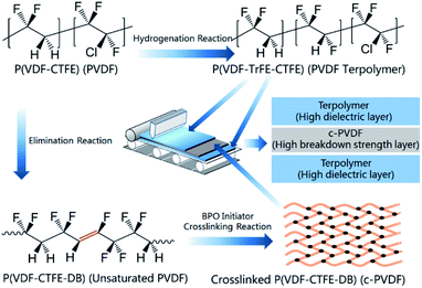 | ||
| Fig. 1 Molecules of P(VDF-CTFE), P(VDF-CTFE-DB), P(VDF-TrFE-CTFE) and procedures for fabricating the tri-layered composite films. | ||
Measurement and characterizations
The phase structures of composite films were analyzed by X-ray diffractometer (Bruker D8 Advanced, Bruker, Cu Kα radiation, λ = 0.15418 nm). The cross-sectional morphologies were observed by scanning electron microscopy (SEM, Quanta 250FEG, FEI, Ltd). The dielectric constant and loss were measured as a function of frequency using an Agilent 4294A precision impedance analyzer (Agilent 4294A, Agilent Technology). The displacement–electric field (D–E) hysteresis loops of the composite films were evaluated at 10 Hz via a ferroelectric test system (Multiferroic 100, Radiant Technologies).Results and discussion
Fig. 2a presents the 1H NMR spectra results of the synthesized unsaturated PVDF and PVDF terpolymer based on the starting P(VDF-CTFE). Comparing with that of P(VDF-CTFE), the unsaturated PVDF shows an extra chemical shifts at 6.6–6.2 ppm (m, 1H, –CH![[double bond, length as m-dash]](https://www.rsc.org/images/entities/char_e001.gif) CFH–), which refers to the double-bond structure in the molecular chain of unsaturated PVDF. The chemical structure of PVDF terpolymer was characterized via 1H NMR spectra as follows: 2.6–2.1 ppm (m, 2H, –CF2–CH2CH2–CF2–, head-to-head bonding arrangements of VDF units), 3.6–3.2 ppm (m, 1H, –CF2–CFCl–, CTFE), 3.7–2.6 ppm (m, 2H, –CH2–CF2–CH2–CF2–), 5.9–5.3 ppm (m, 1H, –CF2–CFH–, TrFE).32 XRD results of the tri-layered architecture composites are listed in Fig. S2.† The measurements for c-PVDF and PVDF terpolymer are aslo displayed for comparisons. In the XRD patterns, the sharp diffraction peaks at 2θ of 18.8° and 19.7° are indexed as γ-phased c-PVDF and β-phased PVDF terpolymer, respectively. For the tri-layered composites, the positions of the diffraction peaks keep no shift, while the intensity ratio between 18.8° and 19.7° peaks increases obviously with adding the inner-layer c-PVDF volume, indicating that the phase structures of the composites are simply combined from that of the corresponding single polymer layers. The data of the FTIR spectra in Fig. S3† are consistent with that of the XRD patters. The 1730 cm−1 peak, which is from the charactering absorption of –CH
CFH–), which refers to the double-bond structure in the molecular chain of unsaturated PVDF. The chemical structure of PVDF terpolymer was characterized via 1H NMR spectra as follows: 2.6–2.1 ppm (m, 2H, –CF2–CH2CH2–CF2–, head-to-head bonding arrangements of VDF units), 3.6–3.2 ppm (m, 1H, –CF2–CFCl–, CTFE), 3.7–2.6 ppm (m, 2H, –CH2–CF2–CH2–CF2–), 5.9–5.3 ppm (m, 1H, –CF2–CFH–, TrFE).32 XRD results of the tri-layered architecture composites are listed in Fig. S2.† The measurements for c-PVDF and PVDF terpolymer are aslo displayed for comparisons. In the XRD patterns, the sharp diffraction peaks at 2θ of 18.8° and 19.7° are indexed as γ-phased c-PVDF and β-phased PVDF terpolymer, respectively. For the tri-layered composites, the positions of the diffraction peaks keep no shift, while the intensity ratio between 18.8° and 19.7° peaks increases obviously with adding the inner-layer c-PVDF volume, indicating that the phase structures of the composites are simply combined from that of the corresponding single polymer layers. The data of the FTIR spectra in Fig. S3† are consistent with that of the XRD patters. The 1730 cm−1 peak, which is from the charactering absorption of –CH![[double bond, length as m-dash]](https://www.rsc.org/images/entities/char_e001.gif) CH–, increase gradually with the increase of volume fractions of c-PVDF inner-layer.
CH–, increase gradually with the increase of volume fractions of c-PVDF inner-layer.
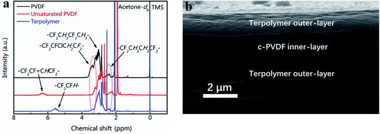 | ||
| Fig. 2 (a) 1H NMR spectra of PVDF, unsaturated and terpolymer PVDF-based polymers. (b) Cross-section SEM image of tri-layered composite film with 30 vol% of c-PVDF. | ||
The volume fraction of c-PVDF in the tri-layered structure composites is controlled by adjusting the thicknesses of c-PVDF middle layer. The cross-sectional morphology of tri-layered structure composite has been characterized in Fig. 2b displays the morphology image of the composite with 30 vol% of c-PVDF. As marked in the image, the outer layers are PVDF terpolymers and the middle is c-PVDF layer. The composite films show high quality with well-bonded layers, as well as dense structure of invisible defects such as pores and flaws. The total thicknesses of tri-layered composite films were ∼6 μm, where the top and bottom layers are set symmetric.
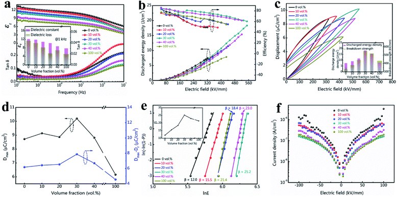
The dielectric properties of tri-layered architecture composites are shown in Fig. 3a. All the samples present a decreased dielectric constant while increasing the frequency, implying similar intrinsic dielectric response in the dielectric polymers. The dielectric response mechanisms of these fluoropolymers are ascribed to dipoles' arrangement of the amorphous phase and weak oscillation of the crystal phase.33 At low frequency range (100 Hz ≤ f ≤ 0.1 MHz), the change in εr is slow when the dipoles' reversals can keep up with the switches of the electric fields. The dipoles will lag behind the electric field switch and require longer relaxing period to arrange at higher frequencies ranging from 0.1 MHz to 10 MHz, which contributes to lower permittivity, higher dielectric loss, and larger dielectric decreasing slop.34,35 In the samples, PVDF terpolymer show highest relative dielectric constant (εr) with a value of 12.1 at 1 kHz, while c-PVDF show smallest εr value of 7.7 at 1 kHz. The decreased εr is attributed to the restricted dipole mobility by crosslinked network structure in c-PVDF. Hence, the composites present a gradually decreased εr with incorporation of more c-PVDF volume. On the other hand, the composite with 30 vol% of c-PVDF still displays a relatively large εr of 10.2 at 1 kHz, merely 15.7% reduction over PVDF terpolymer. Furthermore, the composites exhibit lower dielectric loss than PVDF terpolymer. The greatly depressed dielectric loss is attributed to suppressed carrier transport owing to the existence of crosslinked barrier layer.
The energy storage density and charge–discharge efficiency can be deduced from the hysteresis loop areas of the all-organic PVDF-based films. According to formulae (1) and (2), Ue is mainly determined by the maximal displacement (Dmax) and the breakdown strength (Eb). Improvement in Eb will nearly lead to a square enhancement in Ue, since higher Eb could results in larger Dmax. The data in Fig. 3b verify that the tri-layered structure composite films exhibit substantially enhanced breakdown strength and discharge energy density by introducing the inner barrier layer of c-PVDF. Some jumps in energy storage efficiency are found in the curves, which may originate from the setting variation of the ferroelectric test system. Fig. 3c shows the D–E loops of tri-layered structure composites and the single PVDF-based polymers. The exerted electric field intensities for the D–E loop measurements were set to near the characteristic breakdown strengths of these composite films. From the D–E loops, PVDF terpolymer film presents a charge displacement of 8.7 μC cm−2 at 320 kV mm−1 intensity, corresponding to an Ue 7.5 J cm−3. On the other hand, the composite with 30 vol% contents of c-PVDF delivers the maximum charge displacement over 10 μC cm−2 at 550 kV mm−1 electric field with Ue up to 18.3 J cm−3, which is 2.44 times as that of PVDF terpolymer film. The discharged energy densities and the maximum breakdown strengths of these composite films are summarized in the inset of Fig. 3c. In addition, the introduction of inner c-PVDF barrier layer is also beneficial to the charge–discharge efficiency (η), which is defined as the ratio of the discharged energy to the total energy storage density (shown in Fig. S1†). While a η of 49.5% is observed in PVDF terpolymer film under 300 kV mm−1 electric field, the composite film with 30 vol% of c-PVDF displays a much enhanced η up to 77.4% at the same electric field intensity, under electric field intensity of 550 kV mm−1, the composite film still presents a η of 60.6%. As narrated in the preceding paragraph, large Dmax offers high charging energy density during a complete cycle of charge–discharge process. On the other hand, lower Dr in the D–E loop benefits higher discharge efficiency. The displacement difference ΔD, which is defined as the difference between the maximum displacement Dmax and the remanent Dr, i.e., ΔD = Dmax − Dr, can be directly used to indicate the energy storage density as well as the efficiency. Fig. 3d presents the Dmax and ΔD values of the tri-layered structure composites and the single PVDF-based polymers under their endurable maximum electric fields. As the figure shown, with increasing c-PVDF volume in the tri-layered structure composites, ΔD increases continuously and reaches to ∼7.87 μC cm−2 at the composition of 30 vol% c-PVDF, which is even higher than that of PVDF terpolymer (∼6.18 μC cm−2), indicating enhanced energy storage density and efficiency with 30 vol% c-PVDF addition. The samples show higher discharge efficiency at lower electric field intensity, which is related with less domain switches thus smaller Dr at lower electric field for these PVDF-based ferroelectric polymers during charging–discharging process. For example, the composite film with 30 vol% c-PVDF show improved energy efficiency from 60.6% at 550 kV mm−1 to 77.4% at 300 kV mm−1 electric field, which corresponds to a reduction in ferroelectric Dr of 2.32 μC cm−2 to 0.7 μC cm−2.
Since breakdown strength is critical to the energy storage density and the reliability of the capacitor, Fig. 3e compares the characteristic breakdown parameters of the composites, PVDF terpolymer and c-PVDF analyzed by Weibull distribution function (3):36
 | (3) |
To demonstrate the breakdown strength enhancement and electric field redistribution due to the introduction of the inner layer, the electric potential distributions with thickness variations in each layer are calculated by phase-field simulation. During the simulation, the tri-layered structure composites can be approximately considered as three capacitors with different dielectrics connected in series. The electric field distribution can be calculated as the following equations:25,26
 | (4) |
 | (5) |
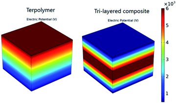 | ||
| Fig. 4 Cross-sectional profiles of simulated local distributions of the electric field in a single PVDF terpolymer film and a tri-layered structure composite film with 30 vol% c-PVDF. | ||
| Sample | Eouter (kV mm−1) | Einner (kV mm−1) | Eb (kV mm−1) |
|---|---|---|---|
| a For the electric field calculations, the εinner and εouter are set to 7.7 and 12.1, and applied voltage is set to 6000 V, respectively. | |||
| 0 vol% | — | — | 325.6 |
| 10 vol% | 362.0 | 556.2 | 381.6 |
| 20 vol% | 400.8 | 613.9 | 443.3 |
| 30 vol% | 475.1 | 728.7 | 550.9 |
| 40 vol% | 430.1 | 658.2 | 521.3 |
| 100 vol% | — | — | 431.9 |
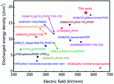
The energy storage density and breakdown strength of the tri-layered structure composites in this work and some recently reported polymer-based composites are compared in Fig. 5.1,14,25–29,36–43 As it can be seen, many strategies have been employed to improve the energy storage properties of the dielectrics and achieved certain positive effects. The involved dielectric materials include organic–inorganic hybrids, organic mixtures, sandwich structures with combining different organic layers. Among these dielectrics, organic–inorganic hybrid structured composites are made of ceramic fillers and polymer matrix. Because of the large mismatch in dielectric constant between ceramic and polymer phases, the organic–inorganic hybrids usually show enhanced charge displacement but relatively poor breakdown strength. As to the organic mixtures such as PMMA/P(VDF-TrFE-CFE), the breakdown strength and the energy storage efficiency are enhanced. Its charge displacement is relatively poor because PMMA addition is linear dielectric with low dielectric constant. In this work, by introducing the crosslinked structure in the tri-layered all-organic composites, the breakdown strength Eb and the charge displacement Dmax are enhanced simultaneously so that a maximum Ue of 18.3 J cm−3 at 550 kV mm−1 are achieved in the tri-layered structure composite film with 30 vol% c-PVDF. The energy storage performances of the research can be attractive to the applications of the flexible energy storage dielectrics.
Conclusions
In summary, all-organic tri-layered structure composites for energy storage are fabricated using a layer-by-layer casting technology. In the composites, the middle c-PVDF layer effectively undertakes the main local electric field because of its low dielectric permittivity. Introduction of crosslinked structure to c-PVDF layer substantially enhances the breakdown strength of the tri-layered structure composites. Coupling with the large electric displacement of PVDF terpolymer layers, an ultrahigh discharge energy density of 18.3 J cm−3 and an energy storage efficiency of 60.6% are achieved at 550 kV mm−1 in the tri-layered structure composite, which is much improved than that of the single PVDF terpolymer and the commercial BOPP. The researches provide a promising strategy to fabricate high-storage-density devices via designing the all-organic films for advanced microelectronic applications.Author contributions
Xiongjie Li: investigation, methodology, visualization, validation, writing – original draft. Ying Yang: conceptualization, resources, supervision, writing – review & editing. Yiping Wang: supervision, writing – review & editing. Shuting Pang: investigation, validation. Jingjing Shi: investigation. Xinchi Ma: investigation. Kongjun Zhu: supervision, funding acquisition.Conflicts of interest
There are no conflicts to declare.Acknowledgements
This work was financially supported by National Natural Science Foundation of China (No. U2037603); the 111 Project (No. B12021); Jiangsu Provincial Science and Technology Project (No. BZ2020006); the Key Research and Development Program of Jiangsu Province (No. BE2018008-2) and the Priority Academic Program Development of Jiangsu Higher Education Institutions.Notes and references
- J. Chen, Y. F. Wang, X. W. Xu, Q. B. Yuan, Y. J. Niu, Q. Wang and H. Wang, J. Mater. Chem. A, 2019, 7, 3729–3736 RSC.
- Q. Chen, Y. Shen, S. Zhang and Q. M. Zhang, Annu. Rev. Mater. Res., 2015, 45, 433–458 CrossRef CAS.
- B. Chu, X. Zhou, K. Ren, B. Neese, M. Lin, Q. Wang, F. Bauer and Q. M. Zhang, Science, 2006, 313, 334–336 CrossRef CAS PubMed.
- Q. Li, K. Han, M. R. Gadinski, G. Zhang and Q. Wang, Adv. Mater., 2014, 26, 6244–6249 CrossRef CAS PubMed.
- S. B. Tan, X. Hu, S. J. Ding, Z. C. Zhang, H. Y. Li and L. J. Yang, J. Mater. Chem. A, 2013, 1, 10353–10361 RSC.
- J. Wu, A. Mahajan, L. Riekehr, H. Zhang, B. Yang, N. Meng, Z. Zhang and H. Yan, Nano Energy, 2018, 50, 723–732 CrossRef CAS.
- Q. G. Chi, T. Ma, Y. Zhang, Y. Cui, C. G. Zhang, J. Q. Lin, X. Wang and Q. Q. Lei, J. Mater. Chem. A, 2017, 5, 16757–16766 RSC.
- S. Wu, W. Li, M. Lin, Q. Burlingame, Q. Chen, A. Payzant, K. Xiao and Q. Zhang, Adv. Mater., 2013, 25, 1734–1738 CrossRef CAS PubMed.
- L. Wang, H. Luo, X. Zhou, X. Yuan, K. Zhou and D. Zhang, Composites, Part A, 2019, 117, 369–376 CrossRef CAS.
- X. Zhang, J. Y. Jiang, Z. H. Shen, Z. K. Dan, M. Li, Y. H. Lin, C. W. Nan, L. Q. Chen and Y. Shen, Adv. Mater., 2018, 30, 1707269 CrossRef PubMed.
- F. Guan, J. Wang, J. Pan, Q. Wang and L. Zhu, Macromolecules, 2010, 43, 6739–6748 CrossRef CAS.
- J. Jiang, Z. Shen, X. Cai, J. Qian, Z. Dan, Y. Lin, B. Liu, C. W. Nan, L. Q. Chen and Y. Shen, Adv. Energy Mater., 2019, 9, 1803411 CrossRef.
- Z. C. Zhang, Q. J. Meng and T. C. M. Chung, Polymer, 2009, 50, 707–715 CrossRef CAS.
- J. Chen, X. Xiong, Q. Zhang, L. Shui, S. Shen, H. Yang, Z. Zhu and F. Zhang, Polymers, 2019, 11, 526 CrossRef PubMed.
- Z. C. Zhang and T. C. M. Chung, Macromolecules, 2007, 40, 783–785 CrossRef CAS.
- X. T. Ren, N. Meng, H. X. Yan, E. Bilotti and M. J. Reece, Polymer, 2019, 168, 246–254 CrossRef CAS.
- D. Zhang, W. Liu, R. Guo, K. Zhou and H. Luo, Adv. Sci., 2018, 5, 1700512 CrossRef PubMed.
- Y. Feng, B. Miao, H. Gong, Y. Xie, X. Wei and Z. Zhang, ACS Appl. Mater. Interfaces, 2016, 8, 19054–19065 CrossRef CAS PubMed.
- Y. Guo, N. Meng, Y. Zhang, J. Xu, E. Pawlikowska, C. Wu, M. Szafran and F. Gao, Polymer, 2020, 203, 122777 CrossRef CAS.
- Y. F. Feng, J. X. Zhang, J. B. Hu, S. C. Li and C. Peng, Electron. Mater. Lett., 2018, 14, 187–197 CrossRef CAS.
- D. R. Wang, T. Zhou, J. W. Zha, J. Zhao, C. Y. Shi and Z. M. Dang, J. Mater. Chem. A, 2013, 1, 6162–6168 RSC.
- V. Tomer, E. Manias and C. A. Randall, J. Appl. Phys., 2011, 110, 044107 CrossRef.
- K. Yu, Y. Niu, F. Xiang, Y. Zhou, Y. Bai and H. Wang, J. Appl. Phys., 2013, 114, 174107 CrossRef.
- Y. Wang, L. Wang, Q. Yuan, J. Chen, Y. Niu, X. Xu, Y. Cheng, B. Yao, Q. Wang and H. Wang, Nano Energy, 2018, 44, 364–370 CrossRef CAS.
- P. H. Hu, Y. Shen, Y. H. Guan, X. H. Zhang, Y. H. Lin, Q. M. Zhang and C. W. Nan, Adv. Funct. Mater., 2014, 24, 3172–3178 CrossRef CAS.
- P. H. Hu, J. J. Wang, Y. Shen, Y. H. Guan, Y. H. Lin and C. W. Nan, J. Mater. Chem. A, 2013, 1, 12321 RSC.
- Z. Pan, B. Liu, J. Zhai, L. Yao, K. Yang and B. Shen, Nano Energy, 2017, 40, 587–595 CrossRef CAS.
- Y. Shen, Y. Hu, W. Chen, J. Wang, Y. Guan, J. Du, X. Zhang, J. Ma, M. Li and Y. Lin, Nano Energy, 2015, 18, 176–186 CrossRef CAS.
- Y. Zhang, T. D. Zhang, L. Z. Liu, Q. G. Chi, C. H. Zhang, Q. G. Chen, Y. Cui, X. Wang and Q. Q. Lei, J. Phys. Chem. C, 2018, 122, 1500–1512 CrossRef CAS.
- S. B. Tan, J. J. Li, G. X. Gao, H. Y. Li and Z. C. Zhang, J. Mater. Chem., 2012, 22, 18496–18504 RSC.
- Y. Lu, J. Claude, Q. Zhang and Q. Wang, Macromolecules, 2006, 39, 6962–6968 CrossRef CAS.
- Z. M. Wang, Z. C. Zhang and T. C. M. Chung, Macromolecules, 2006, 39, 4268–4271 CrossRef CAS.
- B. Hahn, J. Wendorff and D. Y. Yoon, Macromolecules, 1985, 18, 718–721 CrossRef CAS.
- Y. J. Lee, S. R. Ham, J. H. Kim, T. H. Yoo, S. R. Kim, Y. T. Lee, D. K. Hwang, B. Angadi, W. S. Seo, B. K. Ju and W. K. Choi, Sci. Rep., 2018, 8, 4851 CrossRef CAS PubMed.
- U. Yaqoob and G. S. Chung, J. Alloys Compd., 2017, 695, 1231–1236 CrossRef CAS.
- Y. Shen, D. Shen, X. Zhang, J. Jiang, Z. Dan, Y. Song, Y. Lin, M. Li and C. W. Nan, J. Mater. Chem. A, 2016, 4, 8359–8365 RSC.
- H. Ye, X. Zhang, C. Xu, B. Han and L. Xu, J. Mater. Chem. C, 2018, 6, 11144–11155 RSC.
- B. Xie, H. Zhang, Q. Zhang, J. Zang, C. Yang, Q. Wang, M. Y. Li and S. Jiang, J. Mater. Chem. A, 2017, 5, 6070–6078 RSC.
- X. B. Zhang, L. Yuan, Q. B. Guan, G. Z. Liang and A. J. Gu, J. Mater. Chem. A, 2017, 5, 21909–21918 RSC.
- H. Luo, D. Zhang, L. Wang, C. Chen, J. Zhou and K. Zhou, RSC Adv., 2015, 5, 52809–52816 RSC.
- Y. K. Zhu, P. K. Jiang and X. Y. Huang, Compos. Sci. Technol., 2019, 179, 115–124 CrossRef CAS.
- S. Luo, J. Yu, S. Yu, R. Sun, L. Cao, W. Liao and C. Wong, Adv. Energy Mater., 2019, 9, 1803204 CrossRef.
- J. P. Lao, H. A. Xie, Z. Q. Shi, G. Li, B. Li, G. H. Hu, Q. L. Yang and C. X. Xiong, ACS Sustainable Chem. Eng., 2018, 6, 7151–7158 CrossRef CAS.
Footnote |
| † Electronic supplementary information (ESI) available. See DOI: 10.1039/d1ra01423d |
| This journal is © The Royal Society of Chemistry 2021 |

