
 Open Access Article
 This Open Access Article is licensed under a Creative Commons Attribution-Non Commercial 3.0 Unported Licence
Synthesis, structure and the Hirshfeld surface analysis of three novel metal-tiron coordination complexes†
Ranjay K. Tiwariabcd,
Ipsha Shrutiabd and
J. N. Behera *abd
*abd
aSchool of Chemical Sciences, National Institute of Science Education and Research (NISER), Bhubaneswar, P.O. Jatni, Khurda, Odisha-752050, India. E-mail: jnbehera@niser.ac.in; Web: http://niser.ac.in/jnbehera
bHomi Bhabha National Institute, Mumbai, India
cDepartment of Chemistry, University of Delhi Faculty of Science, North Campus, Delhi-110007, India
dCentre for Interdisciplinary Sciences (CIS), NISER, 752050, Jatni, Odisha, India
First published on 12th March 2021
Abstract
Three novel metal-tiron (4,5-dihydroxy-1,3-benzenedisulfonic acid disodium salt) and other pillared ligand bpy (4,4′-bipyridyl)-centered coordination polymers of the formulae [Cd(tiron)(bpy)2(H2O)2]·0.5(H2O), 1, [Co3(tiron-bpy)2(bpy)(H2O)8]·(H2O)2, 2, and [Ba2(tiron-bpy)2(H2O)4][solvent], 3, were successfully synthesized under hydrothermal conditions. The as-synthesized materials were well characterized by complimentary techniques such as single-crystal X-ray diffraction, powder X-ray diffraction, Fourier-transform infrared spectroscopy and thermogravimetric analysis techniques. The as-synthesized coordination polymers of 1 and 2 featured 1D chains, while 3 shows a layered structure. Co-based 2 shows linear trinuclear Co(II) ions and these Co(II) ions have antiferromagnetic interactions among themselves. The structure of 1 features a zig-zag chain formed by the linkage between monodentate tiron ligands and octahedral Cd(II) ions, interconnected by a twisted bpy ligand, 2 shows a linear chain constructed from corner-sharing trinuclear octahedral Co(II) ions and coordinated with a tridentate tiron-bpy adduct ligand, whereas 3 shows nona-coordinated Ba(II) ions sharing edges with other Ba(II) ions and connected by hexadentate tiron-bridged structures resulting in a layered structure. In 2 and 3, the bpy nitrogen attacks at the ortho position of the tiron ligand and forms an in situ ligand adduct. The central metal ions show an octahedral geometry in 1 (Cd(II) ions) and 2 (Co(II) ions), but nona-coordination of Ba(II) ions in 3. The short interatomic interactions in the crystal structures were evaluated by mapping the Hirshfeld surface process using pseudo-mirrored 2D fingerprint plots. The major short interatomic interactions H⋯H, O⋯H and C⋯H cover the Hirshfeld surfaces.
Introduction
The incalculable research of crystalline materials such as coordination polymers (CPs) MOFs, PCMOFs, and COFs has attracted considerable attention in the last decade owing to their diverse architectures, topological structures and their prospective applications for gas storage,1–3 dielectrics,4,5 electrical conductivity,6 catalysis,7,8 magnetism,9,10 luminescence,11,12 etc. Generally, the crystallinity of materials provides important information on the nature of bonding between the metal and the organic linker, the functional group attached to the organic linker, void details, H-bonding and other interactions between molecules, the possibility of proton conduction, etc., and helps in understanding the stability of materials and the feasible applications of materials.13,14Nevertheless, the assortment of the functional organic chelating ligand is an essential step towards crystal engineering, rational design and synthesis of the functional coordination polymers. Hence, the carboxylate and phosphonate group-containing ligands are the most effective functional ligands and flooded research based on metal carboxylate and metal phosphonate polymers.15–18 The structures of phosphonate and sulfonate groups are analogous to each other. However, the studies of metal-sulfonate-based polymers investigating their excellent applications in fuel cells are noticeably fewer than those investigating metal-carboxylate and metal-phosphonate based polymers.19
It is recognized that the organosulfonate-based ligands are weaker ligands as sulfonate-containing ligands are easily soluble in water, the bonding interaction between metal-sulfonate ligands is weaker and the solvent (water) cannot be dislocated from the primary coordination sphere of metal ions. Hence, sulfonate-based ligands provide controlled availability of spatial arrangement of bonding sites on metal ions, which facilitates a constraint in the progress of network structures to engender low-dimensional crystalline materials and low-dimensional structural predictability instead of extended networks. This can be attributed to the flexible connectivity of the sulfonate anions to the metal ions or amorphous structure formation20–22 although the sulfonate anions show strong Lewis acidity.21 Shimizu and coworker reported the first metal-sulfonate coordinate polymer in 2001.22 Keeping all these facts in mind, we selected tiron (4,5-dihydroxy-1,3-benzenedisulfonic acid disodium salt) as a ligand for the preparation of metal-sulfonate-phenol polymers. The ligand tiron is preferred in chelating and bridging ligation due to the following typical points (1) the tiron ligand encompassing two sulfonate and two phenol (catechol) functional groups have been less known; (2) the coordination reaction between the metal ions and tiron ligand can straightforwardly help in the formation of novel structures and topology; and (3) the sulfonate group settled at the ortho, meta and para positions of a benzene ring with respect to the phenol group and can display various coordination modes of ligands via their prospective oxygen donors.23–25
Our aim is to check the consequence of the crystal structures and their fascinating properties of metal coordination polymers by varying different metal ions with sulfonate-phenol-based tiron ligands and 4,4′-bipyridyl (bpy) ligands. Herein, we present a mixed-linker approach to synthesize metal-sulfonate-phenol-centered coordination polymers possessing a tiron-bpy adduct ligand with a zig-zag structure. The coordinate polymers were synthesized under hydrothermal conditions and characterized by single-crystal X-ray diffraction, powder X-ray diffraction, FTIR spectroscopy, thermogravimetric analysis (TGA). The magnetic properties of 2 owes the antiferromagnetic interaction amongst adjacent Co(II) ions. Interestingly, in case of 2 and 3, the in situ formation of an adduct of tiron-bpy ligand (Fig. 1) takes place in the presence of metal nitrate salts (Co(II) and Ba(II) ions), during the course of the reaction. However, 1 and 2 featured 1D chain, whereas 3 showed a layered structure.
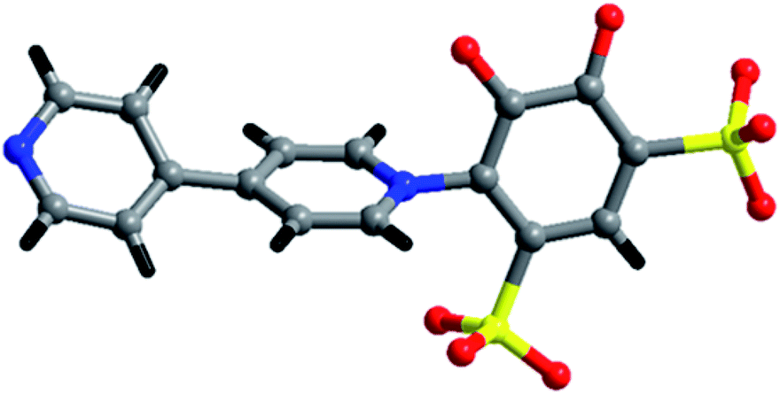 | ||
| Fig. 1 Schematic diagram of the tiron-bpy adduct ligand. | ||
Experimental
Materials and methods
All the chemicals were purchased from standard chemical suppliers and used without further purification. Physical measurements like thermogravimetric analyses were carried out at a ramp rate of 10 °C min−1 under a continuous flow of nitrogen gas using a Discovery TGA by TA Instruments-Waters Lab. Powder X-ray diffraction data were collected using a Bruker D8 Advance instrument with a DAVINCI design fitted to an HTK 16 temperature chamber X-ray powder diffractometer using Cu Kα radiation (λ = 1.5418 Å). Single-crystal structure determination by X-ray diffraction was performed using a Bruker AXS KAPPA-Apex II diffractometer equipped with an Oxford Cryostream low-temperature device and a fine focus sealed-tube X-ray source (Mo Kα radiation, λ = 0.71073 Å, graphite monochromated) operating at 50 kV and 30 mA.Synthesis of [Cd(tiron)(bpy)2(H2O)2]·0.5(H2O), 1
First, 4,5-dihydroxy-1,3-benzenedisulfonate disodium salt [C6H4O8S2Na2] (0.166 g, 0.5 mmol) and 4,4′-bipyridyl [C10H8N2] (0.078 g, 0.5 mmol) were weighed into a 20 mL capacity beaker. Then, 10 mL of double distilled water was added into the 20 mL beaker. The resulting solution was kept under constant stirring for 30 minutes followed by the addition of Cd(NO3)2·4H2O (0.154 g, 0.5 mmol) to the reaction mixture. The reaction mixture was further stirred at room temperature for another 30 minutes. The reaction mixture (white ppt.) was then transferred into a 15 mL Teflon lined stainless steel autoclave. Finally, the stainless steel autoclave was kept in a preheated hot air oven at 140 °C for 72 h. This reaction mixture was cooled to room temperature over 24 h and gave needle-shaped transparent colorless crystals at the bottom of the Teflon container with a light brown powder. These crystals were filtered and washed with distilled water and dried under vacuum for further characterization (yield 30% with respect to Cd). IR (KBr, cm−1): ν(O–H) = 3436, ν(C![[double bond, length as m-dash]](https://www.rsc.org/images/entities/char_e001.gif) N) = 1637, ν(CC) = 1589, 1544, 1477, ν(CN) = 1423, δ(OH) = 1375, ν(C–O) = 1288, ν(SO32−) = 1222, 1159, 1097, 1027, 946, δ(C–H) = 846, 771, 732, ν(C–S) = 601. Anal. Calc.: C, 41.80; H, 3.51; N, 7.50; S, 8.58%. Found: C: 41.91; H: 3.47; N, 7.58; S, 8.78%.
N) = 1637, ν(CC) = 1589, 1544, 1477, ν(CN) = 1423, δ(OH) = 1375, ν(C–O) = 1288, ν(SO32−) = 1222, 1159, 1097, 1027, 946, δ(C–H) = 846, 771, 732, ν(C–S) = 601. Anal. Calc.: C, 41.80; H, 3.51; N, 7.50; S, 8.58%. Found: C: 41.91; H: 3.47; N, 7.58; S, 8.78%.
Synthesis of [Co3(tiron-bpy)2(bpy)(H2O)8]·(H2O)2, 2
First, 4,5-dihydroxy-1,3-benzenedisulfonate disodium salt [C6H4O8S2Na2] (0.166 g, 0.5 mmol) and 4,4′-bipyridyl [C10H8N2] (0.078 g, 0.5 mmol) were weighed into a 20 mL capacity beaker. Then, 10 mL of double distilled water was added into the 20 mL beaker. The resulting solution was kept under constant stirring for 30 minutes followed by the addition of Co(NO3)2·6H2O (0.146 g, 0.5 mmol) to the reaction mixture. The reaction mixture was further stirred at room temperature for another 30 minutes and transferred into a 23 mL Teflon lined stainless steel autoclave. Finally, the stainless-steel autoclave was kept in a preheated hot air oven at 140 °C for 72 h. This reaction mixture was cooled to room temperature over 24 h, which gave plate-shaped transparent orange color crystals at the bottom of the Teflon container. These crystals were filtered and washed with distilled water and dried under vacuum for further characterization (yield 60% with respect to Co). IR (KBr, cm−1): ν(O–H) = 3438, ν(CN) = 1612, ν(CC) = 1544, 1518, 1448, ν(CN) = 1409, δ(OH) = 1310, ν(C–O) = 1265, ν(SO32−) = 1209, 1143, 1085, 1037, 962, δ(C–H) = 858, 762, 721, ν(C–S) = 609. Anal. Calc.: C, 37.09; H, 3.71; N, 6.18; S, 9.43%. Found: C, 37.20; H, 3.43; N, 6.09; S, 9.19%.
Synthesis of [Ba2(tiron-bpy)2(H2O)4][solvent], 3
First, 4,5-dihydroxy-1,3-benzenedisulfonic acid disodium salt [C6H4O8S2Na2] (0.166 g, 0.5 mmol) and 4,4′-bipyridyl [C10H8N2] (0.078 g, 0.5 mmol) were weighed into a 20 mL capacity beaker. Then, 10 mL of double distilled water was added into the 20 mL beaker. The resulting solution was kept under constant stirring for 30 minutes followed by the addition of Ba(NO3)2·xH2O (0.131 g, 0.5 mmol) to the reaction mixture. The reaction mixture was further stirred at room temperature for another 1 h and transferred into a 15 mL Teflon-lined stainless steel autoclave. Finally, the stainless steel autoclave was kept in a preheated hot air oven at 140 °C for 144 h. This reaction mixture was cooled to room temperature over 24 h, and plate-shaped transparent brown color crystals were obtained at the bottom of the Teflon container. These crystals were filtered and washed with distilled water and dried under vacuum for further characterization (yield 68% with respect to Ba). IR (KBr, cm−1): ν(O–H) = 3488, ν(CN) = 1632, ν(CC) = 1568, 1525, 1439, ν(CN) = 1415, δ(OH) = 1305, ν(C–O) = 1270, ν(SO32−) = 1216, 1151, 1079, 1045, 973, δ(C–H) = 862, 762, 731, ν(C–S) = 605. Anal. Calc.: C, 35.43; H, 3.40; N, 5.90; S, 9.01%. Found: C, 35.63; H, 3.64; N, 5.93; S, 9.12%.
Crystallography
A suitable single crystal of 1–3 was carefully selected under a polarizing microscope and mounted at the tip of a thin glass fiber using cyanoacrylate (super glue) adhesive. The single-crystal structure determination of 1 and 3 was performed by X-ray diffraction using a Bruker AXS-KAPPA Apex II diffractometer equipped with a normal focus, 2.4 kW sealed-tube X-ray source (Mo-Kα radiation = 0.71073 Å) operating at 50 kV and 30 mA, whereas the single crystal structure determination of 2 was performed using a SuperNova, Dual, Cu at home/near, Pilatus 200 K diffractometer equipped with a microfocus, 2.4 kW sealed-tube X-ray source (Cu-Kα radiation = 1.5418 Å) operating at 40 kV and 40 mA. Using the Olex2 software, the structures were solved by the direct method using SHELXT-2014 and refined on F2 by a full-matrix least-squares technique using the SHELXL-2014 program package.26 An empirical absorption correction based on symmetry-equivalent reflections was applied using SADABS.27 The graphics programs DIAMOND28 and ORTEP29 were used to draw the structures. Non-hydrogen atoms were refined anisotropically. In the crystallographic refinement, the hydrogen atoms were treated as horse-riding atoms using the SHELXL default parameters. In the case of 1, the lattice water hydrogen atoms were not positioned on Fourier map, and the oxygen atom O3W of water is present as an isolated oxygen atom, one of the sulfonate group of tiron ligand being disordered, at two places, namely, S1 and S1a with occupancy of 55.45% and 44.55% respectively; and the oxygen atoms of sulfonate group is O2, O3 and O2A, O3A with occupancy 55.86 and 44.14% respectively, which was solved by PART instruction, which is also echoed in the check-cif report of 1 having associated ‘A’ level alert. However, in the refinement, hydrogen atoms were added. We show only the highest occupancy atoms in the diagram. In 3, the crystal lattice contains the highly disordered bpy guest molecule in the structure. Therefore, the high electron density peaks around the guest molecules (two water and half bpy units in the asymmetric unit) were squeezed using the PLATON program package.30 However, the surrounding of aqua ligand O2W has been squeezed, and this is resounded in the check-cif report of 3 (B alert). The details of crystal structure refinement parameters for 1–3 are given in Table 1, whereas the hydrogen bonding interaction and other short interactions are given in Table S1.†| Parameter | 1 | 2 | 3 |
|---|---|---|---|
| Formula | [Cd(tiron)(bpy)2(H2O)2]·0.5(H2O) | [Co3(tiron-bpy)2(bpy)(H2O)8]·(H2O)2 | [Ba2(tiron-bpy)2(H2O)4][solvent] |
| Radiation source | Mo Kα | Cu Kα | Mo Kα |
| Mr | 1474.02 | 1355.88 | 595.75 |
| Crystal system | Monoclinic | Triclinic | Monoclinic |
| Space group | P21/c | P![[1 with combining macron]](https://www.rsc.org/images/entities/char_0031_0304.gif) |
P21/c |
| a/Å | 7.3724(2) | 9.0487(4) | 15.8633(18) |
| b/Å | 33.4103(9) | 10.2616(3) | 17.2055(19) |
| c/Å | 11.7744(3) | 16.0633(4) | 8.9423(11) |
| α/Å | 90 | 75.272(2) | 90 |
| β/° | 104.009(2) | 89.528(3) | 100.403(8) |
| γ/° | 90 | 66.293(4) | 90 |
| V/Å3 | 2813.94(13) | 1313.35(9) | 2400.6(5) |
| Z | 2 | 1 | 4 |
| ρcalc (g cm−3) | 1.740 | 1.714 | 1.648 |
| λ(Mo Kα) [Å] | 0.71073 | 1.54184 | 0.71073 |
| μ/mm−1 μ (cm−1) | 0.992 | 9.657 | 1.878 |
| θ range (deg) | 1.884 to 26.372 | 5.573 to 66.593 | 1.762 to 25.349 |
| Reflections collected | 43![[thin space (1/6-em)]](https://www.rsc.org/images/entities/char_2009.gif) 935 935 |
11712 |
21507 |
| Unique reflections [R(int)] | 5747 [0.0800] | 4603 [0.0758] | 4372 [0.0834] |
| Data/restraints/parameters | 5747/20/440 | 4603/4/380 | 4372 /6 /285 |
| GOF on F2 | 1.030 | 1.097 | 0.981 |
| R1 and R2 [I > 2σ(I)] | 0.0373, 0.0708 | 0.0852, 0.2365 | 0.0384, 0.0825 |
| R1 and R2 (all data) | 0.0602, 0.0796 | 0.0906, 0.2435 | 0.0541, 0.0902 |
| Largest residual peaks (e Å−3) | 0.50 and −0.59 | 1.66 and −0.90 | 1.20 and −0.83 |
| CCDC no. | 1969467 | 1969468 | 1969469 |
Hirshfeld surface analysis and 2D fingerprint plot
The short contact between the neighbouring molecules in the crystal lattice structures was computed using Crystal Explorer 17.5.31 Crystal Explorer 17.5 was used to investigate the Hirshfeld surfaces32 of the crystal structures and envisaged their associated two-dimensional (2D) fingerprint plot33 of short interatomic contacts and the interaction energy of the lattice. The inalterable refined crystallographic information file (.cif) is imported into the CrystalExplorer 17.5 (ref. 31) software as an input file. The normalized contact distance dnorm is described in the term of the van der Waals radii (vdW) of atoms, di and de parameters, and represented over the colour gradient from red to blue. The dnorm contact distance was calculated from the following equation:where the parameter di is the distance between the Hirshfeld surface and the closest nucleus inside the surface, and the other parameter de is the distance from the Hirshfeld surface to the nearby nucleus outside the surface. In addition, rvdWi and rvdWe are the van der Waals radii of the atoms. The normalised short contact dnorm was plotted between di and de and the surface displayed by the colour gradient from red, white to blue. The relative influence of the short interatomic contact above the Hirshfeld surface is envisaged by the colour gradient (red to blue) in the fingerprint plots. The set of interaction contact of precise atomic pairs is emphasised by analysing the pseudo-mirrored 2D fingerprint plots. The 2D fingerprint plots between di and de were established in the range 0.6–2.8 Å containing the reciprocal contact. The dark-red spots on the dnorm surface arise as a result of the short interatomic contacts, while the other intermolecular interactions appear as light-red spots. Blue colour spot shows the porous region or long-range intermolecular interaction or non-interacting region. The parameters used on 2D fingerprint plots between di and de shows the distances among the Hirshfeld surface from the nearby atomic centres, about the relative van der Waals radii [vdW] and the details are given in Table S3.†
Results and discussion
Polymers 1–3 were obtained by the hydrothermal reaction, taking an equimolar amount of metal ions, tiron ligands and 4,4′-bpy, where these reactants were mixed in water and heated up to 140 °C. In particular, the tetra-functional tiron ligand contains a rigid benzene ring having two adjacent hydroxyl groups, which can be chelated with metal ions and other two meta-positioned sulfonates can bind with the metal or take part in the H-bonding and construction of the coordination polymers with assorted structures, topology and important applications. Here, the formation of an in situ adduct of tiron-bpy ligands is noteworthy. All the details of the crystallographic refinement of unit cells, data collection and reduction for 1–3 are provided in Table 1. The molecular formulae of 1–3 are [Cd(tiron)(bpy)2(H2O)2]·0.5(H2O), 1, [Co3(tiron-bpy)2(bpy)(H2O)8]·(H2O)2, 2, and [Ba2(tiron-bpy)2(H2O)4][solvent] 3.Crystallographic analysis of [Cd(tiron)(bpy)2(H2O)2]·0.5(H2O), 1
Polymer 1 was synthesized by a hydrothermal method, in which the Cd(II) ions, tiron and bpy were mixed in water and heated at 140 °C. The single-crystal X-ray analysis data suggested that the colorless needle-shaped crystals were crystallized in a monoclinic system having the P21/c achiral space group. It was formulated as [Cd(tiron)(bpy)2(H2O)2]·0.5(H2O) and formed a one-dimensional chain structure. Each asymmetric unit constructed by one Cd(II) ion, one tiron ligand, two bpy ligands, two aqua ligands and a half unit of disordered water molecule trapped in the lattice with all the atoms has 100% occupancy (O3W disorder water molecule has 50% occupancy), as shown in Fig. S1.†The Cd(II) ions were connected with three nitrogen atoms of three bpy ligands, one oxygen atom of the sulfonate tiron ligand, and two aqua ligands, which collectively form octahedral structures around Cd(II) ions. In CdO3N3 octahedra, all the bond lengths are in the usual range with the average Cd–N bond length of 2.336 Å, for Cd–Osulfonate it is 2.335 Å and for Cd–Oaqua it is 2.314 Å.34 The selected Cd–O bond lengths are given in Table 2; complete bond lengths and bond angles are listed in Table S2.† The Cd atoms in the octahedral unit have +2 oxidation states, which are intended by the bond valence sum calculations.34,35 The total charge on the tiron ligand is −2.
| a Symmetry transformations used to generate equivalent atoms: a = −1 + x, 3/2 − y, −1/2 + z; b = 1 − x, 2 − y, 1 − z; c = x, 3/2 − y, −1/2 + z; d = 1 − x, 1 − y, −z; e = 1 − x, 1/2 + y, 1/2 − z. | |||||
|---|---|---|---|---|---|
| [Cd(tiron)(bpy)2(H2O)2]·0.5(H2O), 1 | |||||
| Cd1–O1 | 2.335(3) | Cd1–O2W | 2.333(3) | Cd1–N2a | 2.316(3) |
| Cd1–O1W | 2.290(3) | Cd1–N1 | 2.333(3) | Cd1–N3 | 2.358(3) |
|
|||||
| [Co3(tiron-bpy)2(bpy)(H2O)8]·(H2O)2, 2 | |||||
| Co1–O1 | 2.203(3) | Co1–O1W | 2.121(4) | Co2–O2W | 2.132(4) |
| Co1–O1b | 2.203(3) | Co1–O1Wb | 2.121(4) | Co2–O3W | 2.062(4) |
| Co1–O2 | 2.000(3) | Co2–O1 | 2.142(3) | Co2–O4W | 2.104(5) |
| Co1–O2b | 2.000(3) | Co2–O3 | 2.058(4) | Co2–N3 | 2.174(4) |
|
|||||
| [Ba2(tiron-bpy)2(H2O)4][solvent], 3 | |||||
| Ba1–O1 | 2.699(3) | Ba1–O4c | 2.864(4) | Ba1–O1W | 2.831(4) |
| Ba1–O1c | 2.724(3) | Ba1–O6d | 2.796(4) | Ba1–O1Wc | 2.872(4) |
| Ba1–O3 | 2.861(4) | Ba1–O7e | 2.877(4) | Ba1–O2W | 2.878(7) |
The lattice of 1 is depicted in Fig. 3, the sulfonate oxygen atom of tiron ligand is bonded to Cd(II) ions via η1, μ1 manner (Fig. S5(a)†), whereas the other sulfonate and two phenolate oxygen atoms of the tiron ligand remain non-bonded. The tiron ligand bonded with the octahedral CdO3N3 unit, and these octahedra were further bridged by a bpy unit and results in the infinite one-dimensional zigzag chain, running along the c-axis, as depicted in Fig. 2. Furthermore, one of the bpy ligands connected with Cd(II) ions, and the other end of bpy is free. One of the sulfonate group of tiron ligands is located in the inter-chain space of the crystal lattice and will provide a path for proton conduction, because of free sulfonate and the hydroxyl group of tiron ligands.14,36 Lattice water molecules are lying in between the chains. The non-bonded sulfonate group, phenolate group, aqua ligand and water molecules were involved in the strong intricate H-bonding and provide strength to the molecule. The H-bonds are listed in Table S1,† and they range between 2.486 (11) and 3.438 (12) Å. Unfortunately, the H-bonding is confined within the chain, thus there is no increase in the dimensionality of 1.
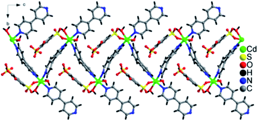 | ||
| Fig. 2 One-dimensional zigzag chain formation due to coordination of Cd-tiron-bpy and running along the c-axis in 1. | ||
 | ||
| Fig. 3 H-bonding network pattern in the lattice of 1, (a–c) viewing from different positions of lattice and showing as dashed lines. | ||
Crystallographic analysis of [Co3(tiron-bpy)2(bpy)(H2O)8]·(H2O)2, 2
Polymer 2 was synthesized similarly to 1, where the Cd salt was replaced by the cobalt salt. The single-crystal X-ray diffraction dataset of 2 suggested that the plate-shaped orange colored crystals belong to an achiral P space group in the triclinic crystal system. From Fig. S2,† it can be observed that the asymmetric unit of 2 is made up of one full and one half occupied units of Co(II) ions, one unit of tiron-bpy adduct ligands (in situ formation), a half unit of bpy ligands, four units of aqua ligands and one water molecule trapped in the lattice. Co1(II) ions are present in the special position with 50% occupancy. The coordination environment of Co1(II) is constructed from four phenolate oxygen atoms from two tiron-bpy adduct ligands present at an equatorial plane and it forms a basal unit; the axial position of Co1(II) ions was occupied by two aqua ligands, resulting in the octahedral environment around Co1(II) ions. The Co2(II) ions are coordinated with one phenolate oxygen atom and one sulfonate oxygen atom from the same tiron-bpy adduct ligand, and one N1 nitrogen atom of bpy, whereas the remaining three sites of Co2(II) ions are coordinated with three aqua ligands and form an octahedra structure around Co2(II) ions. Each of the Co(II) ions has octahedral geometries. The tiron-bpy adduct ligand has −3 charge, which collectively comes from two adjacent deprotonated phenolate groups (catecholate group), and provides −1 charge and −2 charge from two sulfonate groups. Thus, the −3 charge on the tiron-bpy adduct ligand is neutralized by the 1.5 unit Co(II) ions. In the Co1O6, the Co–O bond length ranges from 2.000 to 2.203 Å, which fall in the normal range. In another octahedral unit of Co2O5N, the Co–Ophenolate bond length is 2.058 Å, the Co–Osulfonated bond length is 2.058 Å, the Co–N bond length is 2.174 Å, and the average Co–Oaqua bond length is 2.0993 Å. All the bond lengths fall in the normal range, as reported in the literature.5 The selected Co–O bond lengths are given in Table 2; complete bond lengths and bond angles are listed in Table S2.†
Furthermore, the tiron-bpy adduct ligand shows chelating nature towards Co(II) ions as well as bridging coordination modes, as shown in Fig. S5(b),† where O3 oxygen atoms of sulfonate coordinated with one Co(II) ion, and show μ1–η1:η1 coordination mode. Another sulfonate group of the same tiron-bpy adduct ligand does not take part in bonding. Furthermore, the O1 and O2 phenolic oxygen atoms of the same ligand chelate to one Co1(II) ion, and O1 phenolic oxygen atom also connected to another Co2(II) ion via a μ2-bridging linkage. In general, the C–O bond lengths in metal-catecholates range from 1.34 to 1.36 Å. The average bond length of C–O is found to be 1.3095 Å in 2, which is slightly less than this range. The tiron-bpy adduct ligands are anchored to the Co(II) ions and observed in 2, which suggests that the presence of variable connectivity modes of tiron ligands of some metal-tiron complexes is based on the phenolic and sulfonate groups in various deprotonated states, as previously reported in the literature. The bond valence sum calculations of Co atoms were found to be 2.01 in the compound, and hence, the Co ions are present in +2 oxidation states.35,41 Tiron ligand shows only one kind of coordination modes in 2, a tridentate ligand as shown in Fig. 4, S2 and S5(b),† which gives one sulfonate group adjoining to the phenolic group to chelate Co2(II) ions. The remaining non-coordinated sulfonate group take part in the H-bonding, and one phenolic oxygen atom bridges Co1 and Co2(II) ions, while other phenolic oxygen atoms coordinated to Co1(II) ions.
 | ||
| Fig. 4 A polyhedral view of 1D polymeric chain running along the a-axis, in a lattice of 2. | ||
In the crystal lattice, the tiron adduct ligand anchored to the Co1(II) ions and formed Co1O6 octahedra, these Co1O6 octahedra further linked with Co2(II) ions via a common O1 oxygen atom in a μ2-bridging fashion and resulted in a Co3O14 cluster, as shown in Fig. 4. Furthermore, these Co3O14 clusters were bridged by bpy ligands via nitrogen atoms and formed a linear tri-nuclear Co cluster (Co3O14N2). Furthermore, the two trinuclear Co3O14N2 are bridged by the bpy ligand and extended along the c-axis resulting in a 1D polymeric chain structure. The Co3O14N2 are present in the center of the chain. The inter chain distances fall in the range of 9.0487–10.6072 Å. The lattice water molecule O5W is inhabited in the inter-chain space. Polymer 2 gets extra stability from the H-bonding, which occurs between the oxygen atom of sulfonate, aqua ligand and lattice water molecules and ranges from 2.611 to 3.442 Å, as shown in Fig. 5.
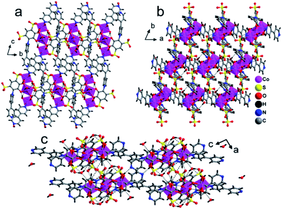 | ||
| Fig. 5 H-Bonding interaction in the crystal lattice of 2 between the sulfonate oxygen atom, phenolate oxygen, aqua ligand and lattice water molecules along the (a) a-axis, (b) c-axis and (c) b-axis. | ||
Crystallographic analysis of [Ba2(tiron-bpy)2(H2O)4][solvent], 3
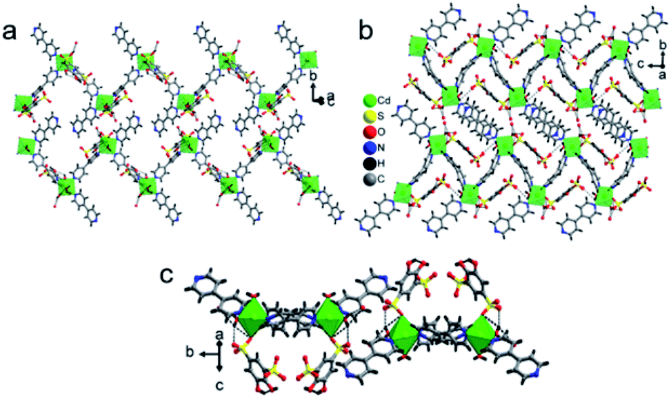
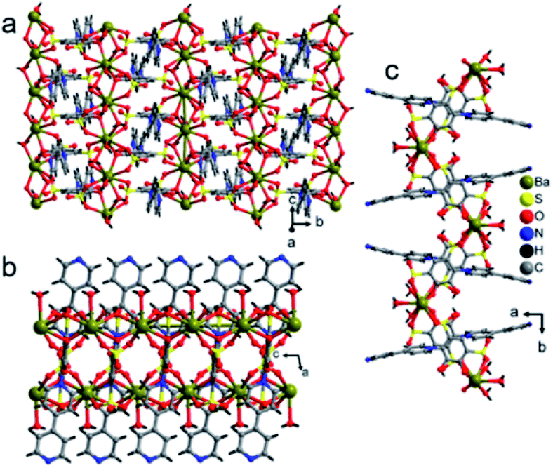
Polymer 3 was synthesized by the previous protocol similar to that of 1 and 2, and the brown color crystal of 3 demonstrated a layered structure and formulated as [Ba2(tiron-bpy)2(H2O)4]·(bpy)(H2O)4; the crystal of 3 exist in the monoclinic crystal system with the achiral P21/c space group. The asymmetric unit of 3 was constructed from one Ba(II) ion, one tiron-bpy adduct ligand, and two aqua ligands. The crystal lattice contains two lattice water molecules and highly disordered guest bpy molecules. The highly disordered bpy guest molecules and lattice water molecules were squeezed from the crystal structure using the SQUEEZE program of the PLATON software programme package by fixing the probing radius at 1.20 Å in the PLATON program in this crystal structural simulation, as shown in Fig. S3.†30 In 3, the Ba(II) ion is nona-coordinated surrounded by nine oxygen atoms coming from four sulfonate oxygen atoms of two different tiron-bpy adduct ligands, two phenolic oxygen atoms from two tiron-bpy adduct ligands, two aqua-bridged oxygen atoms connected to Ba(II) ions and one terminal aqua ligand to provide BaO9 polyhedra. The tiron-bpy adduct ligand has −2 electrical charge in the compound, the one of the deprotonated phenolate is taking part in the bonding with Ba(II) ions and another phenolate group is protonated and remains non-bonded, whereas two sulfonate groups give −2 charge and each sulfonate is bonded with Ba(II) ions. Hence, the −2 electrical charge on the tiron-bpy adduct ligand is balanced by Ba(II) ions. In BaO9, the sulfonated Ba–O bond lengths fall in the range of 2.699–2.877 Å, the average bridged aqua ligand Ba–O is 2.831 Å, Ba–Ophenolic is 2.699 Å and Ba–Oaqua is 2.878 Å, all the bond lengths being in the acceptable range.37 The selected Ba–O bond lengths are given in Table 2; complete bond lengths and bond angles are listed in Table S2.† The bond valence sum calculations of Ba in 3 were accounted to be 2.011, which suggest that Ba has +2 oxidation states.35 Each of the sulfonate group of the tiron-bpy adduct ligand is connected with two Ba(II) ions, whereas the phenolate oxygen is bonded with two Ba(II) ions, the other phenolate group remains non bonded. The tiron-bpy adduct ligands show only one type of connectivity mode in the hexadentate ligand, as shown in Fig. S5(c).† All the sulfonate groups of the tiron-bpy ligand adduct provide their two oxygen atoms toward four Ba(II) ions in a η2–μ2 fashion (one sulfonate group bonded with two Ba(II) ions). Another sulfonate group next to the phenolic group chelates the Ba(II) ion. The protonated phenolic oxygen atom O2 remains non-coordinated. The other phenolic oxygen atom O1 is linked with two Ba(II) ions via the μ2-coordination mode and perpendicular to the tiron-bpy adduct ligand.Furthermore, only phenolic oxygen atoms O1 of the tiron-bpy adduct ligand are connected to two Ba(II) ions via a μ2-bridging linkage mode. The tiron-bpy adduct ligands are anchored to four Ba(II) ions, which is observed in the molecular unit of 3, as shown in Fig. S3.† Hence, the tiron-bpy adduct ligand is connected with four Ba(II) ions, a tetradentate ligand as shown in Fig. S3.†
The crystal lattice of 3 is shown in Fig. 6 and 7, the Ba(II) ions are anchored by the surrounding oxygen atoms and they form a BaO9 polyhedra. The two BaO9 polyhedra are connected to each other through a bridging O1W aqua ligand and phenolic oxygen atom O1 via edge-sharing and resulted in a [Ba–O–Ba] 1D chain along the c-axis as shown in Fig. 6 and S4.† The adjacent Ba(II) ions are separated by 4.4751 Å. Furthermore, the [Ba–O–Ba] 1D chains are interconnected with oxygen atoms of the sulfonate group of the tiron-bpy adduct ligand in the b-axis via the η2–μ2 coordination mode (Fig. S5(c)†) and form a zigzag-shaped or Z-shaped 2D metal-sulfonate layered structure extending in the bc-plane (Fig. 6a and 7). The two tiron units were bridged via Ba(II) ions and form a V-shape, the angle between tiron-Ba-tiron is 104.85°. The adjacent layers are separated by 10.26 Å. The layers lie in the bc-plane with an interlayer-space of 10.26 Å.
 | ||
| Fig. 6 (a) A Ba-tiron-bpy-Ba chain extending along the c-axis, (b) a Ba-tiron-bpy layer structure extending in the bc-plane in 3 and viewed along the b-axis and (c) a view of the Ba-tiron-bpy layer structure of 3 in the crystallographic c-axis. | ||
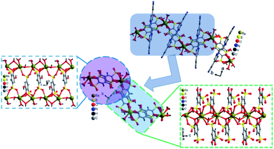 | ||
| Fig. 7 Schematic diagram showing the intersection of a Z-shaped [Ba2(tiron-bpy)2(H2O)4] layer of 3, where the Ba–O–Ba chain interconnected with the tiron ligand, in the part the two tiron units linked with Ba(II) ions in V shape with an angle 104.85° (different colours are used for better visualization). The bpy units are removed for clarity. | ||
The crystal structure contains 24.87% voids with 596.1 Å3 free volume and 54 electrons per asymmetric unit, which corresponds to two lattice water molecules and half unit of highly disordered bpy guest molecules, which have been conquered by a selecting squeeze command using the PLATON software program. The high electron density resembles the highly disordered one bpy unit of guest molecules and four water molecules.
The coordinated aqua ligands are situated in the interlayer region. The H-bonding interactions show crucial roles for holding layers together in the crystal packing and provide extra stability to 3. The H-bond lengths of 3 are listed in Table S1.† From Fig. 8, the neighboring [Ba2(tiron-bpy)2(H2O)4] layers are interconnected by an intricate H-bonding, held between sulfonate oxygen atoms, nitrogen atoms of the tiron-bpy adduct ligand and the aqua ligand, which fall in the range of 2.801–3.270 Å. The O⋯O separations range from 2.772 to 2.853 Å, and the infinite 2D layered transmitted into the H-bonded 3D-network structure due to the intricate H-bonding, as shown in Fig. 8. Together, the H-bonds engender an extensive H-bonded 3D network and add the overall strength and stability to the crystal lattice of 3.
 | ||
| Fig. 8 H-Bonding pattern with the polyhedral representation of the layered structure in 3 viewed along the c-axis. | ||
Magnetic property
The molecular unit of 2 contains linear trinuclear Co(II) ions, which prompted us to investigate the magnetic coupling exchange interaction between adjacent trinuclear Co(II) ions, and we collected the temperature variable and field variable magnetic susceptibility data of a crystalline sample of 2 in the temperature range 2–300 K at 1000 Oe and an external applied magnetic field. The curve of χM and χM−1 and χMT against the temperature of 2 is shown in Fig. 9.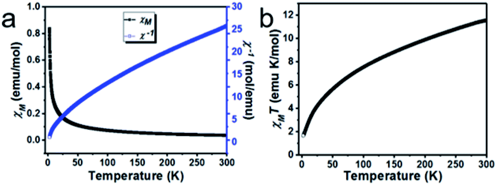 | ||
| Fig. 9 (a) Thermal dependency magnetic susceptibility and its inverse data of 2 at 1000 Oe external applied magnetic field, and (b) thermal dependent χMT product at 1000 Oe external applied magnetic field. | ||
The temperature-dependent magnetic susceptibility is shown in Fig. 9a, which revealed that the χM and χM−1 values are 0.0385 emu per mol at 300 K and 25.94 mol per emu respectively, as the temperature drops to 2 K from 300 K, the χM starts increases and reaches 0.8390 emu per mol at 2 K; these data suggest the anisotropic alignment of a Co(II) ion. The plot of χMT against temperature is shown in Fig. 9b; the observed room temperature χMT value is 11.562 emu per mol K, which is much higher than the expected spin only value of 5.625 emu per mol K at 300 K for the three octahedral magnetism-isolated high spin Co(II) metal ions (S = 3/2 and g = 2), and this indicates the presence of considerable orbital coupling contribution to the magnetic behaviour. The value of χM−1 and χMT decreases, as the sample is cooled to 2 K from 300 K. The inverse of magnetic susceptibility of 2 follows the Curie-Weiss law above 120 K; this is due to the occurrence of thermally populated excited states of Co(II) ions. At a higher temperature, the first-order orbital contribution observed where the spin–orbit coupling J, 4T1g state splits into J = 5/2, 3/2 and 1/2 levels.38 Nevertheless, the χM−1 data of 2 is fitted into the Curie-Weiss law in the temperature range of 120–300 K with θ = −57.0 K.39 The θ values are large, which can be due to the presence of the ligand-field effect in 2. The nature of the interactions between two Co(II) ions is antiferromagnetic, which was concluded from the decrease in the χMT product with the temperature and the negative θ value.40,41 The magnetic moment of 2 shows 5.57 BM, which is higher than spin value 3/2 of 3.87 due to the presence of spin as well as orbital momentum.42
Furthermore, with drop down in the temperature, the product of χMT also gradually drops reaching 1.68 emu per mol K at 2 K, and indicates a dominant role of significant antiferromagnetic coupling amongst the octahedral high spin Co(II) ions and thermal depopulation of the excited state of the Kramers doublets of the octahedral high spin Co(II) metal ions and results in the non-Curie behaviour of the curve.38,43 At 2 K, the product of χM and T is 1.68 emu per mol K, which is much lower than the calculated value for three octahedral magnetism-isolated Co(II) Ising doublets with Seff = 1/2. Thus, the only populated ground state of the Kramers doublets of the octahedral Co(II) ions is observed with Seff = 1/2 (spin effective doublets) at a lower temperature.44–46
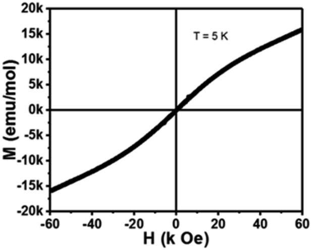
The M–H hysteresis loop of 2 was recorded in the magnetic field range −60 k Oe to +60 k Oe at 5 K and displayed in Fig. 10. The magnetic field-dependent magnetization data of 2 shows a linear field dependence magnetization curve at low temperatures with Hcoer = 0 and s-shaped curve. The magnetic saturation point attends around 60000 Oe. The nature of the curve proposes that 2 is basically a paramagnetic material with antiferromagnetic interactions, demonstrating between the adjacent Co(II) ions.
 | ||
| Fig. 10 Isothermal field-dependent magnetization curve of 2 at 5 K. | ||
The phase purity of as-synthesized bulk materials of 1–3 was examined by powder X-ray diffraction (PXRD) patterns. All the peaks are obtained from measured experimental PXRD data closely compatible with the simulated patterns obtained from SCXRD at room temperature (Fig. S11†).
Furthermore, 1–3 were examined by FTIR spectra to confirm the presence of signature peaks of sulfonate and phenolic groups present in the crystal structure (Fig. S12†). FTIR spectra 1–3 show the νas band at 1250–1170 cm−1 and νs peak in the range of 1110–1050, which belongs to a signature peak of the SO3 groups. The band area in the region 3100–2860 cm−1 corresponds to the aromatic CH stretching mode. In the FTIR spectra, the additional bands in the area 3750–3200 cm−1 could be attributed to the presence of the OH stretching vibration, which belongs to water molecules.
TGA
The thermogravimetric analysis (TGA) of 1–3 was performed in a nitrogen atmosphere in the temperature range of room temperature to 700 °C; the objective of TGA is to study their thermal stability and the structural integrity (Fig. 11). The TGA curve suggests that all 1–3 show continuous weight loss with respect to the increase in temperature. The first weight loss in 1 corresponds to the dehydration step (coordinated and lattice water molecules), which occurs in the temperature range of 30 to 160 °C, and account for the weight loss of 6.36%, (calcd 6.10%, four aqua ligands and one water molecule). Above 260 °C, the tiron and bpy ligands started to decay and the coordination polymers started to collapse. The weight loss was found to be nearly 72.39% (calcd 74.96%), which corresponds to two tiron units and four bpy molecule units. The TGA graph of 2 showed that the weight loss was 15.37% (calculated as 13.28%) in the temperature range of 30–190 °C, which shows the loss of all water molecules. Above 373 °C, the compound begins to disintegrate due to the removal of one unit of tiron-bpy ligand and half unit of bpy ligand and shows 38.53% weight loss (calculated 37.17%). In Fig. 11, the TGA spectra of 3 depicts a 5.73% weight loss below 120 °C (calculated 7.62%), which belongs to the removal of two water molecules. The second step of weight loss was observed around 45.83% from 250 °C to 540 °C, and this step belongs to the decaying of the tiron-bpy adduct ligand.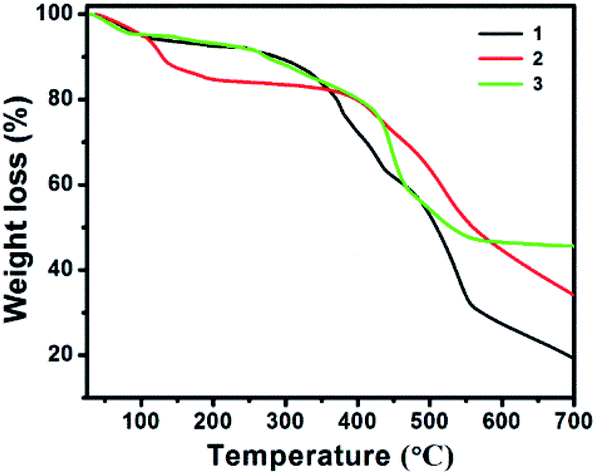 | ||
| Fig. 11 TGA curves of the as-synthesized 1–3. | ||
Hirshfeld surface analysis
The nature of short interatomic interactions in the crystal lattice has been studied by applying the Hirshfeld surface analysis and associated pseudo-mirror 2D (two-dimensional) fingerprint plots over the surface.47–50 Normally, the parameter dnorm plot was assessed by the calculations of the de (external) and di (internal) distances to the nearby atoms. The existence of a red colour patch (surfaces) mark on the blue surface represented a fluctuating intensity amongst the interacting atoms in the dnorm surface plot, which shows the existence of interactions lesser than or equal to the summation of the van der Waals radii of the two interacting nuclei. The strength of short contact is proportional to the intensity of red patches.The Hirshfeld surfaces of 1 cover 580.90 Å2 area and spread over 676.71 Å3 volume with 0.5 isovalue; the scaled colour patches on the surface were generated in between −0.669 a.u. (red colour) and 1.428 a.u. (blue colour), whereas the shape-index plot and curvedness plot are engendered from −1.00 to 1.00 a.u. and −3.745 to 0.341 a.u., respectively, as shown in Fig. 12. The quantitative and envisage of 2D fingerprint plot are shown in Fig. S6† and suggest that the presence of short contacts, and also take part in H-bonding. The H-bonds plays an important role which provides the extra stability. The short interatomic contacts were incurred in H⋯H (26.4%), H⋯O (32.6%), H⋯C (15.9%), H⋯N (7.5%), C⋯C (7.2%), O⋯C (5.0%), O⋯O (1.6%), Cd⋯N (1.6%), C⋯N (1.4%), N⋯N (0.3%), O⋯N (0.3%), H⋯Cd (0.2%) and H⋯S (0.1%) respectively. The 2D fingerprint plots of these short interatomic contacts were shown in Fig. S6.† The major supports are from H⋯H, C⋯H and O⋯H compared to other short interatomic contacts.
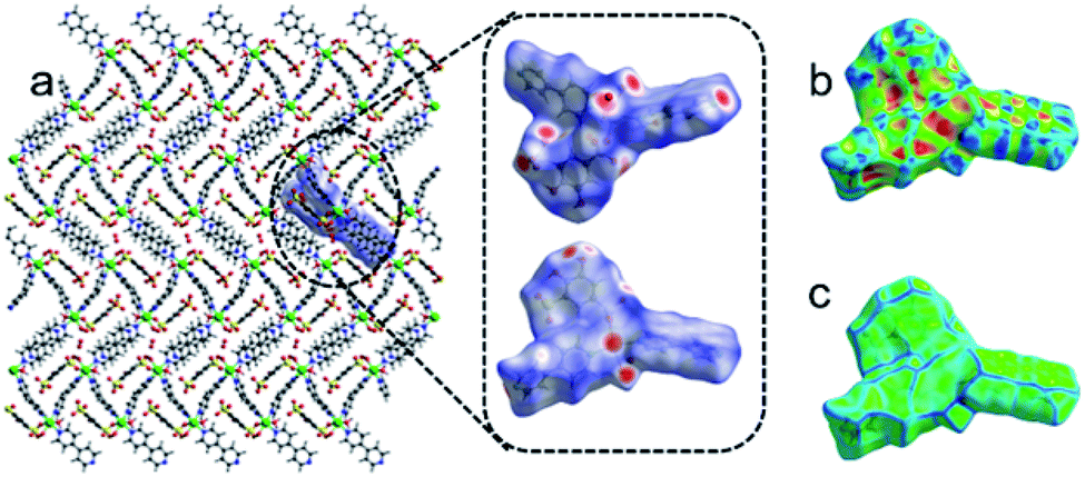 | ||
| Fig. 12 (a) The perspective view of the Hirshfeld surface in the crystal lattice of 1 which is highlighted in the circle and represented the dnorm plot in different direction of lattice, (b) the shape-index plot and (c) curvedness plot in the crystal lattice of 1. | ||
The Hirshfeld surfaces of 2 store 540.68 Å2 area and accumulate is 629.00 Å3 volume with 0.5 isovalue, the scaled colour gradient on the surface generated in the between −1.121 a.u. (red colour) and 1.784 a.u. (blue colour). Whereas the shape-index plot and curvedness plot are engendered from −1.00 to 1.00 a.u. and −4.57 to 0.894 a.u., respectively (Fig. S7†). The 2D fingerprint plot reveals that the interatomic contacts were acquired in between the inside and outside of the surface and shows the percentage of interactions are as follows H⋯H (25.9%), H⋯O (37.9%), H⋯C (21.1%), H⋯N (4.4%), O⋯C (4.4%), Co⋯O (2.2%), C⋯C (2.1%), O⋯O (1.7%), O⋯N (0.9%), H⋯Co (0.2%), and C⋯N (0.1%) respectively. The 2D fingerprint plots of interatomic contacts were depicted in Fig. S8.† The major supports arise from H⋯H, C⋯H and O⋯H interatomic interactions.
In the case of 3, the Hirshfeld surfaces spread over 420.37 Å2 area and holds 450.83 Å3 volume with 0.5 isovalue, the varying scaled color code on the surface engendered in the between −0.661 a.u. (red colour) and 1.425 a.u. (blue colour). Whereas the shape-index plot and curvedness plot are engendered from −1.00 to 1.00 a.u. and −3.847 to 0.970 a.u., respectively as shown in Fig. S9.† Similar to 1 and 2 the 2D fingerprint plot of 3 reveals that the interatomic interactions were acquired in between the inside and outside of the surface and shows the percentage of interactions as follows H⋯H (27.3%), H⋯O (15.67%), H⋯C (4.5%), Ba⋯O (4.7%), O⋯O (8.0%), O⋯C (2.3%), H⋯N (1.7%), C⋯C (1.9%), H⋯Ba (0.4%), C⋯N (0.3%), and O⋯S (0.1%) respectively. The 2D fingerprint plots of interatomic contacts were depicted in Fig. S10.† The major supports arise from H⋯H, C⋯H and O⋯H interatomic interactions.
Henceforth, the overall Hirshfeld surface and their relative 2D fingerprint plots aid to separate and understand the environment of the assorted molecules as well as the symmetry of the independent molecules in the crystal lattice.
Conclusions
Three novel coordination polymers, [Cd(tiron)(bpy)2(H2O)2]·0.5(H2O), 1, [Co3(tiron-bpy)2(bpy)(H2O)8]·(H2O)2, 2, and [Ba2(tiron-bpy)2(H2O)4][solvent], 3, have been successfully synthesized under hydrothermal conditions using tiron and bpy as ligands. These CPs are featured zigzag 1D chain in 1 and 2 and 2D layered coordination polymers in 3. During the hydrothermal reaction, in situ tiron-bpy adduct ligand formation was observed in the presence of cobalt and barium nitrate salts in 2 and 3. The magnetic properties of 2 depict antiferromagnetic interaction amongst the adjacent Co(II) center. The Hirshfeld surface analysis helps to understand the short interatomic interactions in the crystal structures.Conflicts of interest
There are no conflicts to declare.Acknowledgements
We thank Single Crystal CCD X-ray facility at NISER-Bhubaneswar. This work is supported by the Council of Scientific and Industrial Research (CSIR), Govt. of India for the award of a research grant (01(2808)/14/EMR-II).Notes and references
- M. Gupta, N. Chatterjee, D. De, R. Saha, P. K. Chattaraj, C. L. Oliver and P. K. Bharadwaj, Inorg. Chem., 2020, 59, 1810–1822 CrossRef PubMed.
- D. Liu, J.-P. Lang and B. F. Abrahams, J. Am. Chem. Soc., 2011, 133, 11042–11045 CrossRef PubMed.
- D. Saha, Z. Wei and S. Deng, Int. J. Hydrogen Energy, 2008, 33, 7479–7488 CrossRef.
- R. K. Tiwari, J. Kumar and J. Behera, Chem. Commun., 2016, 52, 1282–1285 RSC.
- R. K. Tiwari and J. N. Behera, CrystEngComm, 2018, 20, 6602–6612 RSC.
- A. A. Talin, A. Centrone, A. C. Ford, M. E. Foster, V. Stavila, P. Haney, R. A. Kinney, V. Szalai, F. El Gabaly, H. P. Yoon, F. Léonard and M. D. Allendorf, Science, 2014, 343, 66–69 CrossRef CAS PubMed.
- M. Sabo, A. Henschel, H. Fröde, E. Klemm and S. Kaskel, J. Mater. Chem., 2007, 17, 3827–3832 RSC.
- F.-L. Li, Q. Shao, X. Huang and J.-P. Lang, Angew. Chem., Int. Ed., 2018, 57, 1888–1892 CrossRef PubMed.
- R. K. Tiwari and J. N. Behera, Dalton Trans., 2017, 46, 5911–5917 RSC.
- C. A. Black, J. S. Costa, W. T. Fu, C. Massera, O. Roubeau, S. J. Teat, G. Aromí, P. Gamez and J. Reedijk, Inorg. Chem., 2009, 48, 1062–1068 CrossRef.
- S. Pal and P. K. Bharadwaj, Cryst. Growth Des., 2016, 16, 5852–5858 CrossRef.
- A. Ma, J. Wu, Y. Han, F. Chen, B. Li, S. Cai, H. Huang, A. Singh, A. Kumar and J. Liu, Dalton Trans., 2018, 47, 9627–9633 RSC.
- D. D. Borges, S. Devautour-Vinot, H. Jobic, J. Ollivier, F. Nouar, R. Semino, T. Devic, C. Serre, F. Paesani and G. Maurin, Angew. Chem., Int. Ed., 2016, 55, 3919–3924 CrossRef.
- J. A. Hurd, R. Vaidhyanathan, V. Thangadurai, C. I. Ratcliffe, I. L. Moudrakovski and G. K. Shimizu, Nat. Chem., 2009, 1, 705–710 CrossRef PubMed.
- J. M. Taylor, R. K. Mah, I. L. Moudrakovski, C. I. Ratcliffe, R. Vaidhyanathan and G. K. H. Shimizu, J. Am. Chem. Soc., 2010, 132, 14055–14057 CrossRef.
- J. M. Taylor, K. W. Dawson and G. K. H. Shimizu, J. Am. Chem. Soc., 2013, 135, 1193–1196 CrossRef PubMed.
- A. Clearfield, Prog. Inorg. Chem., 1998, 47, 371–510 Search PubMed.
- B. J. Gunderman and P. J. Squattrito, Inorg. Chem., 1995, 34, 2399–2406 CrossRef.
- G. Zhang, G. Wei, Z. Liu, S. R. J. Oliver and H. Fei, Chem. Mater., 2016, 28, 6276–6281 CrossRef.
- G. K. H. Shimizu, R. Vaidhyanathan and J. M. Taylor, Chem. Soc. Rev., 2009, 38, 1430–1449 RSC.
- A. P. Côté and G. K. H. Shimizu, Coord. Chem. Rev., 2003, 245, 49–64 CrossRef.
- A. P. Côté and G. K. H. Shimizu, Chem. Commun., 2001, 251–252 RSC.
- A. P. Côté and G. K. H. Shimizu, Chem.–Eur. J., 2003, 9, 5361–5370 CrossRef.
- T. S. Sheriff, P. Carr and B. Piggott, Inorg. Chim. Acta, 2003, 348, 115–122 CrossRef.
- L. Guan and Y. Wang, Polyhedron, 2015, 97, 175–181 CrossRef.
- G. Sheldrick, SADABS, SHELXS-2008, SHELXL-2014, University of Göttingen: Göttingen, Germany, 2014 Search PubMed.
- G. M. Sheldrick, SADABS Siemens Area Correction Absorption Program, University of Göttingen, Göttingen, Germany, 1994 Search PubMed.
- W. T. Pennington, J. Appl. Crystallogr., 1999, 32, 1028–1029 CrossRef.
- L. J. Farrugia, J. Appl. Crystallogr., 1997, 30, 565 CrossRef.
- A. Spek, Acta Crystallogr., Sect. C: Struct. Chem., 2015, 71, 9–18 CrossRef CAS.
- M. J. Turner, J. J. McKinnon, S. K. Wolff, D. J. Grimwood, P. R. Spackman, D. Jayatilaka, M. A. Spackman, Crystal Explorer17, University of Western Australia, 2017, http://hirshfeldsurface.net Search PubMed.
- M. A. Spackman and D. Jayatilaka, CrystEngComm, 2009, 11, 19–32 RSC.
- J. J. McKinnon, D. Jayatilaka and M. A. Spackman, Chem. Commun., 2007, 3814–3816 RSC.
- R. K. Tiwari, J. Kumar and J. N. Behera, Dalton Trans., 2017, 46, 15939–15946 RSC.
- I. Brown and D. Altermatt, Acta Crystallogr., 1985, B41, 244–247 CAS.
- T. J. Peckham, J. Schmeisser, M. Rodgers and S. Holdcroft, J. Mater. Chem., 2007, 17, 3255–3268 RSC.
- S. A. Dalrymple and G. K. H. Shimizu, Chem.–Eur. J., 2002, 8, 3010–3015 CrossRef CAS.
- M. Murrie, Chem. Soc. Rev., 2010, 39, 1986–1995 RSC.
- L. Zhang, W. Li, J. Zhang, Z.-J. Li, Y.-Y. Qin, J.-K. Cheng and Y.-G. Yao, Inorg. Chem. Commun., 2008, 11, 279–282 CrossRef CAS.
- Y. Fan, D.-C. Hu, X.-Q. Yao, Y.-X. Yang and J.-C. Liu, New J. Chem., 2016, 40, 5010–5018 RSC.
- X. Feng, J. L. Chen, R. F. Bai, L. Y. Wang, J. T. Wei and X. X. Chen, Inorg. Chem. Commun., 2016, 66, 41–46 CrossRef CAS.
- F. Zhao, Z.-P. Dong, Z.-L. Liu and Y.-Q. Wang, Inorg. Chem. Commun., 2019, 107, 107465 CrossRef CAS.
- X. Liu, L. Sun, H. Zhou, P. Cen, X. Jin, G. Xie, S. Chen and Q. Hu, Inorg. Chem., 2015, 54, 8884–8886 CrossRef CAS PubMed.
- F. Lloret, M. Julve, J. Cano, R. Ruiz-García and E. Pardo, Inorg. Chim. Acta, 2008, 361, 3432–3445 CrossRef CAS.
- M. I. Mocanu, A. A. Patrascu, M. Hillebrand, S. Shova, F. Lloret, M. Julve and M. Andruh, Eur. J. Inorg. Chem., 2019, 2019, 4773–4783 CrossRef CAS.
- J. Vallejo, I. Castro, R. Ruiz-García, J. Cano, M. Julve, F. Lloret, G. De Munno, W. Wernsdorfer and E. Pardo, J. Am. Chem. Soc., 2012, 134, 15704–15707 CrossRef CAS.
- X. Shen, T. Zhang, S. Broderick and K. Rajan, Mol. Syst. Des. Eng., 2018, 3, 826–838 RSC.
- D. Kuriakose and M. R. Prathapachandra Kurup, Inorg. Chim. Acta, 2020, 505, 119472 CrossRef CAS.
- H. Ghasempour, A. Azhdari Tehrani, A. Morsali, J. Wang and P. C. Junk, CrystEngComm, 2016, 18, 2463–2468 RSC.
- K. Rissanen, Chem. Soc. Rev., 2017, 46, 2638–2648 RSC.
Footnote |
| † Electronic supplementary information (ESI) available: BVS calculation, PXRD data as pictures and, H-bonding interactions, complete bond lengths and bond angles as tables. CCDC 1969467 (1); 1969468 (2); and 1969469 (3). For ESI and crystallographic data in CIF or other electronic format see DOI: 10.1039/d1ra00207d |
| This journal is © The Royal Society of Chemistry 2021 |