 Open Access Article
Three-dimensional clusters of peony-shaped CuO nanosheets as a high-rate anode for Li-ion batteries
Lin Hu *a,
Zhong Yang*a,
Hulin Lib,
Xiao Yangb,
Jianping Lia,
Ping Wanga,
Changqing Jina and
Chi Zhanga
aShaanxi Key Laboratory of Optoelectronic Functional Materials and Devices, School of Materials and Chemical Engineering, Xi'an Technological University, Xi'an, 710021, China. E-mail: hulin@xatu.edu.cn; yz750925@163.com; Tel: +8618602925246 Tel: +8618092864735
bPaiersen Environmental Science and Technology Co., Ltd, Wei Nan, 714100, China
First published on 12th March 2021
Abstract
Copper oxide (CuO) has emerged as a promising anode material for lithium-ion batteries (LIBs) due to its high theoretical capacity, low cost and low toxicity to the natural environment. However, the low electronic/ionic conductivity and the imponderable volume expansion problem during the charge and discharge process hinder its practical applications. Herein, we introduced three-dimensional clusters of peony-shaped CuO nanosheets (TCP-CuO) to tackle these problems by increasing the surface of the active material. The unique three-dimensional peony-liked structure not only alleviates the volume expansion problem, but also enhances the electron/ion conductivity. As a result, the TCP-CuO electrode possesses a reversible high capacity of 641.1 mA h g−1 at 0.1 A g−1 after 80 cycles as well as an outstanding rate performance of 531.6 mA h g−1 at a rate of 5C (1C = 674 mA g−1) and excellent cycling durability of 441.1 mA h g−1 at 1 A g−1 after 100 cycles. This work demonstrated a novel strategy for the construction of a well-designed structure for other advanced energy-storage technologies.
Introduction
With the widespread use and urgent demand of new energy, energy storage devices are of critical importance to the utilization of renewable energy sources. Among them, lithium ion batteries (LIBs) are by far the most sophisticated devices and are important in both civil and military fields.1–4 However, the currently used graphitic anode is limited by its theoretical capacity (372 mA h g−1), and it is still hard to meet the demands for high power density devices.5,6 As an alternative, transition metal oxides (TMOs) are emerging as a promising candidate as anode materials due to their high theoretical density which could endow LIBs with desirable electrochemical performance.7–10 Among them, copper oxide (CuO) with high theoretical capacity (674 mA h g−1) and natural amplitude has attracted extensive attention.11,12 However, like most of the TMO anodes, it is also persistently plagued by intrinsic issues, such as imponderable volume expansion problems during the charge and discharge process and low electronic/ionic conductivity. The structural irreversibility caused by volume expansion causes the anode material to crack and leads to pulverization and electrolyte consumption, leading to rapid and remarkable capacity fading and bad rate performance.13Nowadays, numerous CuO nanomaterials with various designed structures have been made to overcome these problems mentioned above.14,15 For example, Mohapatra et al.16 reported a nanoplate and mulberry-like porous shape of CuO and developed as anode materials for LIBs. The CuO nanoplate electrode maintained a reversible charge capacity of 279.3 mA h g−1 at 1C within 70 cycles, and exhibited 150.2 mA h g−1 even at 4C current rate of (1C = 674 mA g−1). Chen et al.17 prepared CuO/nitrogen-doped graphene nanosheet (CuO/N-GNS) which displayed high rate capacity of 485 mA h g−1 at 1 A g−1. Su et al.18 prepared CuO nanowire arrays grown on copper foil with a considerable rate performance of 166 mA h g−1 at 2 A g−1. However, CuO anodes materials with high energy density designed for advanced energy storage devices such as LIBs have yet to be demonstrated.
Herein, we present a facile strategy for preparing three-dimensional clusters of peony-shaped CuO nanosheets (TCP-CuO) through a low-cost solution reaction. The unique peony-shaped nanosheet structure not only facilitates the electron/ion conductivity to realize fast charge, but also alleviate the volume expansion during charging/discharging. As a result, the TCP-CuO electrode exhibits excellent lithium storage capacity, outstanding reversible capacity, remarkable rate performance as well as long term stability.
Experimental
Preparation and characterization
The TCP-CuO product was fabricated by a facile solution reaction based on our previous work.19 In a typical process, a solution of CuSO4·5H2O and hexadecyl trimethyl ammonium bromide (CTAB) were achieved by dissolved them in a mixture of distilled water and ethanol (v/v: 3![[thin space (1/6-em)]](https://www.rsc.org/images/entities/char_2009.gif) :
:![[thin space (1/6-em)]](https://www.rsc.org/images/entities/char_2009.gif) 2) and the solution was continuously stirred for another 30 min. Then, ammonium aqueous solution (10 wt%) was added dropwise into the above solution followed by vigorous stirring for 30 min. Afterwards, NaOH solution was added into the solution under constant stirring. The mixture was continuously stirred for 2 h and aged for another 20 h. Then the obtained black precipitates were centrifugated, washed and then dried at 80 °C. The as-prepared powders were annealed in a muffle furnace at 200 °C for 6 h with a heating rate of 5 °C min−1 to obtain the final TCP-CuO product.
2) and the solution was continuously stirred for another 30 min. Then, ammonium aqueous solution (10 wt%) was added dropwise into the above solution followed by vigorous stirring for 30 min. Afterwards, NaOH solution was added into the solution under constant stirring. The mixture was continuously stirred for 2 h and aged for another 20 h. Then the obtained black precipitates were centrifugated, washed and then dried at 80 °C. The as-prepared powders were annealed in a muffle furnace at 200 °C for 6 h with a heating rate of 5 °C min−1 to obtain the final TCP-CuO product.
The crystal structure of the as-obtained TCP-CuO was characterized by X-ray powder diffraction (XRD) on a SHIMADZUXRD-6000 X-ray diffractometer (Cu Kα radiation). The field emission-scanning electron microscopic (FESEM, ZEISS, SIGMA 500) and transmission electron microscopy (TEM, JEM-2010, JEOL, 200 keV) were utilized to observe the morphology of the TCP-CuO. Fourier transform infrared spectroscopy (FT-IR) was measured on an IS50 Fourier infrared spectrometer. The specific area and pore size distribution were determined by nitrogen adsorption and desorption using a Micromeritics ASAP 2020 analyzer. X-ray photoelectron spectroscopy (XPS) analysis was operated to examine chemical bonds of the sample on a Thermo ESCALAB-250Xi spectrometer.
Electrochemical and kinetic measurements
The electrochemical measurements for LIBs were performed in CR2016-type coin cell, which were assembled in an argon-filled glove box ([O2] < 1 ppm, [H2O] < 1 ppm). The metallic Li foils were used as counter electrodes. The working electrodes were prepared by a slurry coating method on a copper foil with 70% active material (TCP-CuO), 20% acetylene black and 10% sodium carboxymethylcellulose (Na-CMC) using deionized water as the solvent. The separator was Celgard (2500) membrane and the electrolyte was 1 M LiPF6 dissolved in the mixture of ethylene carbonate (EC), ethyl methyl carbonate (EMC) and dimethyl carbonate (DMC). The cells were charged and discharged on a CT4008 battery testing system in the potential range of 0.01–3.0 V (vs. Li/Li+). Cyclic voltammetry (CV) measurements were recorded on a CHI660E electrochemical workstation with a potential scan rate of 0.2 mV s−1 in the range of 0.01–3.0 V.Results and discussion
Material characterization
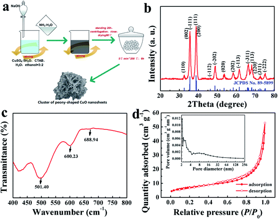
The formation strategy of the TCP-CuO product is described in Fig. 1a. The chemical reactions involved during the formation of the TCP-CuO proceeding are given as follows:| CuSO4·5H2O + 4NH3·H2O → [Cu(NH3)4]SO4 + 9H2O | (1) |
| [Cu(NH3)4]SO4 + 2NaOH → Cu(OH)2 + Na2SO4 + 4NH3 | (2) |
| Cu(OH)2 → CuO + H2O | (3) |
The crystal structure of the final TCP-CuO was shown in Fig. 1b. The diffraction pattern of the product agree well with the standard XRD patterns of CuO (JCPDS No. 89-5899), suggesting the successful formation of the high purity CuO, and the strong diffraction peaks indicate the high crystallinity of the product. Moreover, the chemical composition of the TCP-CuO product were confirmed by FT-IR spectrum. As shown in Fig. 1c, the bands located at 501.40, 600.23 and 688.94 cm−1 are assignable to the characteristic absorption of Cu–O bond, confirming the presence of pure CuO phase.20 The N2 adsorption–desorption isotherm (Fig. 1d) indicates the porous nature of TCP-CuO, with a surface area of 25.34 m2 g−1. In addition, the majority of the pores are smaller than 4 nm (inset of Fig. 1d). XPS analysis was performed to explore the detailed elemental composition and electronic state of the TCP-CuO product. From the survey spectrum, it can be observed only Cu and O species, except for a small amount of adsorbed carbon to calibrate the acquired spectra (Fig. 2a). High-resolution Cu 2p shows the presence of Cu 2p3/2 (934.2 eV) and Cu 2p1/2 (954.1 eV), respectively, indicating the +2 copper oxidation state feature (Fig. 2c). In the O1s spectra, two peaks have been observed at 529.9 and 531.4 eV, which can be assigned to the O2− in CuO and absorbed oxygen, respectively (Fig. 2c). All the above results suggest the formation of pure CuO.
 | ||
| Fig. 2 XPS analysis. (a) Survey spectrum of TCP-CuO. (b) High-resolution spectrum of Cu 2p. (c) High-resolution spectrum of O 1s. | ||
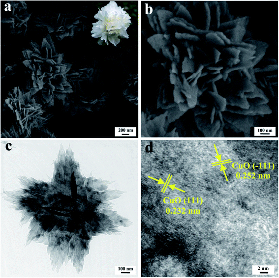
The micro-morphology of the as-prepared TCP-CuO product at different magnifications was shown in Fig. 3a and b. The as-obtained TCP-CuO was observed as uniformly distributed peony-like clusters with diameters range from 600 to 1000 nm which consisted of numerous petals-liked nanosheets with the thickness around 20 nm. The attractive appearance is resemblant with the picture of peony flower obtained online (the inset of Fig. 3a). TEM image (Fig. 3c) further confirms the three-dimensional hierarchical peony-liked nanostructure. In addition, as shown in Fig. 3d, the high-resolution TEM (HRTEM) image displayed that the lattice fringes of 0.252 and 0.232 nm can be index to the (−111) and (111) planes of CuO (JCPDS No. 89-5899), which corresponds to the XRD pattern.
Electrochemical and kinetic characteristics
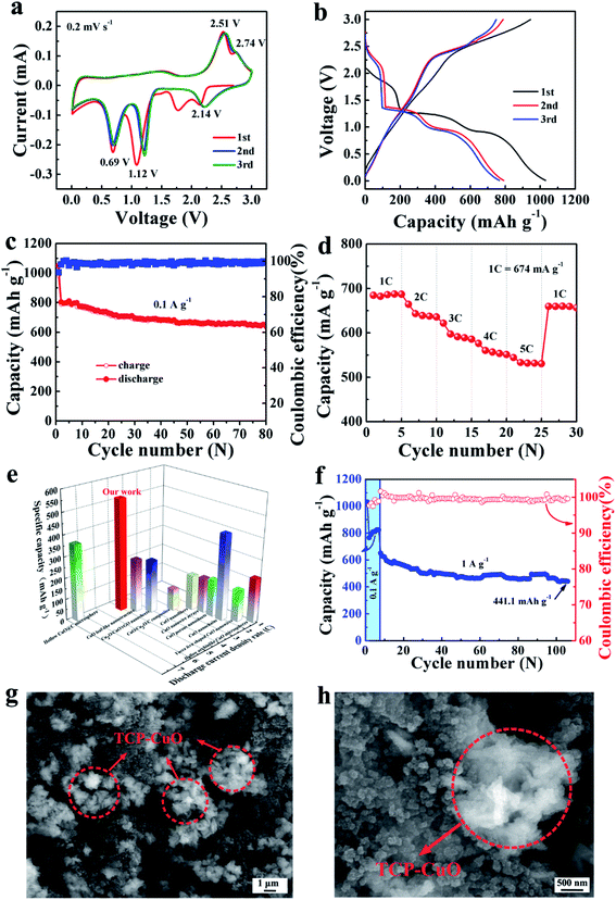
Electrochemical performance of the TCP-CuO anode was investigated for LIBs at room temperature. As show in Fig. 4a, CV curves were recorded at a scan rate of 0.2 mV s−1 within a voltage window of 0.01–3.0 V (vs. Li+/Li). In the first cathodic scan, three peaks at 2.14, 1.12 and 0.69 V (vs. Li+/Li) were assigned to the reductive reaction from CuO to CuII1−xCuIxO1−x/2 (0 ≤ x ≤ 0.4), to Cu2O, and further conversion to Cu and Li2O, respectively. For the anodic scan, two signals peaked at 2.51 and 2.74 V indicate the oxidization of Cu to Cu2O and the formation of CuO phase, respectively.21–23 The corresponding reactions could be described by eqn (4)–(8):21–23 | ||
| Fig. 4 Electrochemical performances of the TCP-CuO electrode in LIBs. (a) CV curves of the TCP-CuO electrode at a scan rate of 0.2 mV s−1. (b) Galvanostatic charge and discharge curves of the TCP-CuO electrode for the first three cycles at a current density of 0.1 A g−1. (c) Cycling performance of the TCP-CuO electrode at 0.1 A g−1. (d) Rate performance of the TCP-CuO electrode at various discharge rates. (e) Comparison of high rate property of the TCP-CuO electrode with other CuO-based electrodes, such as hollow CuO@C microsphere,21 CuO leaf-like nanostructure,25 Cu2O/CuO/rGO nanosheets,26 CuO/Cu2O/C composites,27 CuO nanofibers,28 CuO nanowire arrays,18 CuO porous nanosheets,29 CuO nanochains,22 yucca fern shaped CuO nanowires,30 and hollow urchinlike CuO microspheres.23 (f) Cycling performance of the TCP-CuO electrode as well as coulombic efficiency at 1 A g−1. (g) Low-magnification and (h) high-magnification FESEM images of the TCP-CuO electrode after cycling tests. | ||
The discharge reactions:
| CuO + xLi+ + xe− → CuII1−xCuIxO1−x/2 + x/2Li2O (0 ≤ x ≤ 0.4) | (4) |
| CuII1−xCuIxO1−x/2 + (1 − x)Li+ + (1 − x)e− → 1/2Cu2O + (1 − x)/2Li2O (0 ≤ x ≤ 0.4) | (5) |
| 1/2Cu2O + Li+ + e− → Cu + 1/2Li2O | (6) |
The charge reactions:
| Cu + 1/2Li2O → 1/2Cu2O + Li+ + e− | (7) |
| 1/2Cu2O + 1/2Li2O → CuO + Li+ + e− | (8) |
Note that the difference in area between the first and the subsequent cycles is due to the formation of the solid–electrolyte interface (SEI) film and electrolyte decomposition.18 A slightly shift of the potential in the positive direction in the 2nd and 3rd cycles may be attributed to structural changes during Li+ insertion during the initial lithiation process.21,24 From the 2nd cycle, the CV curves display a good reproducibility, implying a good electrochemical reversibility of the TCP-CuO electrode. The typical charge/discharge voltage curves involves the first three cycles at a current density of 0.1 A g−1 were shown in Fig. 4b. Three distinct voltage plateaus (2.38–1.6, 1.61–1.12 and 1.12–0.05 V) involve the multi-step conversion between CuO and Li during the first discharge process, which is consistent with the CV results. The initial lithiation/delithiation specific capacities are 1049.2 and 983.6 mA h g−1, respectively, corresponding to an initial coulombic efficiency of 93.7%. The formation of SEI films generally led to the irreversible capacity loss in the first cycle. Note that the initial lithiation specific capacity is 1049.2 mA h g−1, which exceeds its theoretical capacity (674 mA h g−1). Such a phenomenon has been reported for different kinds of electrode materials (metals,25 metal oxides,26 and metal sulfides,27 etc.) in LIBs. In this work, the extra capacity may come from the lithium insertion into acetylene black or nanopores, interfacial lithium storage and the formation of a polymeric gel-like SEI film. Fig. 4c shows the cyclic performance of the TCP-CuO electrode at 0.1 A g−1. The electrode still remains a high reversible capacity of 641.1 mA h g−1 after 80 cycles, showing an excellent cycling performance. Fig. 4d represents the rate performance of the TCP-CuO electrode. With the discharge rates increasing from 1C to 5C, the TCP-CuO electrode delivers an average discharge capacity of 685.8, 638.9, 591.1, 556.6 and 531.6 mA h g−1, respectively, which demonstrates a superior rate performance than other reported CuO-based anode materials (summarized in Fig. 4e).18,21–23,28–33 This is attributed to: (i) the distinctive structure of this three-dimensional peony-shape nanosheets facilitates the infiltration of liquid electrolyte and provide more available interfaces for electrochemical reactions, thus accelerating electron/ion transfer; and (ii) the unique peony-like structure can also alleviate the severe volume expansion during charge/discharge process. The cycling durability of the TCP-CuO electrode was tested by first discharging/charging at 0.1 A g−1 for 7 cycles and then 1 A g−1 for 100 cycles. As shown in Fig. 4f, the TCP-CuO electrode remains an outstanding capacity of 441.1 mA h g−1 after 100 cycles with CE around 100%. The morphology of the TCP-CuO electrode at 1 A g−1 after 100 cycles was observed by FESEM as shown in Fig. 4g and h. From the figures, it can be observed that the 3D clusters of flower-shaped CuO nanosheets are still maintained, which demonstrates the 3D structure can alleviate the volume expansion, suggesting the structural stability after long-term cycling.
Based on the above analysis, the superior lithium storage of the TCP-CuO electrode are attributed to the distinct structure and morphology advantages. Firstly, the porous structure with high specific surface area can allow the electrolyte penetration and facilitate rapid electron/ion transfer. Secondly, the 3D flower-liked structure ensures every nanosheet participates in the electrochemical reaction because every nanosheet is surrounded by the electrolyte solution, and promotes more rapid Li+ diffusion through the electrode/electrolyte interface. Meanwhile, the individual nanosheet subunit provides short electron/ion transport path. Finally, the voids existed in the hierarchical architecture can mitigate the volume vibration during the repeat Li+ intercalation/deintercalation processes, and thus inhibit the aggregation the electrode material, thereby improving the high-rate performance and cycling stability.
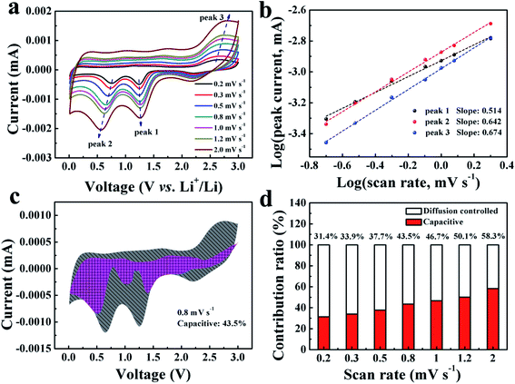
To further investigate the lithium-storage kinetics of the TCP-CuO electrode, CV curves with various scan rates from 0.2 to 2.0 mV s−1 were collected. As shown in Fig. 5a, it was demonstrated that the CV curves could maintain a similar shape while the peaks grow wider as the scan rates increase. The relationship of the peak currents (i) and scan rates (v) fit the following equation:34,35
| i = avb | (9) |
![[thin space (1/6-em)]](https://www.rsc.org/images/entities/char_2009.gif) log(v) + log(a), where a and b are fitting parameters. The value of b could be calculated from the slope of the above equation. Specifically, the b value of 0.5 indicates a diffusion-controlled process, while 1 reveals a capacitive process. The log(i)–log(v) plot of the TCP-CuO electrode is shown in Fig. 5b. The calculated b values are 0.514 (peak 1), 0.642 (peak 2) and 0.674 (peak 3), respectively, demonstrating a hybrid electrochemical process influenced by both diffusion-controlled and pseudocapacitive behavior. In addition, the relative contributions from the capacitive effect (k1v) and the diffusion behavior (k2v1/2) at a constant voltage can be calculated by the following equation:34,35
log(v) + log(a), where a and b are fitting parameters. The value of b could be calculated from the slope of the above equation. Specifically, the b value of 0.5 indicates a diffusion-controlled process, while 1 reveals a capacitive process. The log(i)–log(v) plot of the TCP-CuO electrode is shown in Fig. 5b. The calculated b values are 0.514 (peak 1), 0.642 (peak 2) and 0.674 (peak 3), respectively, demonstrating a hybrid electrochemical process influenced by both diffusion-controlled and pseudocapacitive behavior. In addition, the relative contributions from the capacitive effect (k1v) and the diffusion behavior (k2v1/2) at a constant voltage can be calculated by the following equation:34,35| i(V) = k1v + k2v1/2 | (10) |
Conclusions
In this work, we presented a facile and low-cost strategy to prepare the TCP-CuO material. The TCP-CuO anode material exhibits fascinating electrochemical properties, with outstanding reversible capacity (641.1 mA h g−1 at 0.1 A g−1 after 80 cycles), remarkable rate performance (531.6 mA h g−1 at 5C) and long term stability (441.1 mA h g−1 at 1 A g−1 after 100 cycles). Benefiting from the three-dimensional peony-shaped structure of TCP-CuO, the volume expansion issue of LIBs have been mitigated and the electron/ion conductivity are improved as well. This work will provide a new strategy for fabrication TMO anode materials with high energy density as well as promote their commercial applications in advanced energy storage devices.Conflicts of interest
The authors declare no conflict of interest.Acknowledgements
This project was financially supported by Shaanxi Provincial Education Department to Serve the Local Special Project (19JC022), Key Research and Development Plan of Shaanxi Province (2019ZDLGY05-09) and the Youth Innovation Team of Shaanxi Universities: metal corrosion protection and surface engineering technology.References
- T. Dong, W. U. Arifeen, J. Choi, K. Yoo and T. Ko, Chem. Eng. J., 2020, 398, 125646 CrossRef CAS.
- N. Togasaki, T. Yokoshima, Y. Oguma and T. Osaka, J. Power Sources, 2020, 461, 228168 CrossRef CAS.
- W. Wang, S. Yang, C. Lin, W. Shen, G. Lu, Y. Li and J. Zhang, J. Power Sources, 2020, 451, 227749 CrossRef CAS.
- Z. Zhang, X. Yan, C. Li, H. Song, C. Mao, H. Peng and G. Li, J. Alloys Compd., 2020, 821, 153500 CrossRef CAS.
- C. Yang, X. Y. Zhang, J. Z. Li, J. C. Ma, L. Q. Xu, J. Yang, S. Q. Liu, S. B. Fang, Y. Li, X. T. Sun, X. Y. Yang, F. Pan, J. Lu and D. P. Yu, Electrochim. Acta, 2020, 346, 136244 CrossRef CAS.
- J. Xu, X. Wang, N. Y. Yuan, B. Q. Hu, J. N. Ding and S. H. Ge, J. Power Sources, 2019, 430, 74–79 CrossRef CAS.
- Y. C. Zhao, C. G. Liu, R. W. Yi, Z. Q. Li, Y. B. Chen, Y. Q. Li, I. Mitrovic, S. Taylor, P. Chalker, L. Yang and C. Z. Zhao, Electrochim. Acta, 2020, 345, 136203 CrossRef CAS.
- Y. Zhang and C. D. Wang, Mater. Today Energy, 2020, 16, 100406 CrossRef.
- B. R. Tao, J. L. He and F. J. Miao, Mater. Lett., 2020, 262, 127046 CrossRef CAS.
- Y. F. Feng, K. D. Wu, J. Ke, H. F. Dong, X. P. Huang, C. Bai, D. P. Xiong and M. He, J. Power Sources, 2020, 467, 228357 CrossRef CAS.
- J. Y. Xiang, J. P. Tu, L. Zhang, Y. Zhou, X. L. Wang and S. J. Shi, J. Power Sources, 2010, 195, 313–319 CrossRef CAS.
- X. S. Hu, C. Li, X. B. Lou, Q. Yang and B. W. Hu, J. Mater. Chem. A, 2017, 5, 12828 RSC.
- M. Wan, D. L. Jin, R. Feng, L. M. Si, M. X. Gao and L. H. Yue, Inorg. Chem. Commun., 2011, 14, 38–41 CrossRef CAS.
- W. Yuan, Z. G. Yan, B. Y. Pan, Z. Q. Qiu, J. Luo, Z. H. Tan, Y. Tang and Z. T. Li, J. Alloys Compd., 2017, 719, 353–364 CrossRef CAS.
- Y. Chen, X. H. Peng, X. Y. Fan, Q. Yu, G. Y. Zhao, Y. B. Lin, J. X. Li and Z. G. Huang, J. Solid State Electrochem., 2019, 23, 367–377 CrossRef CAS.
- S. Mohapatra, S. V. Nair, D. Santhanagopalan and A. K. Rai, Electrochim. Acta, 2016, 206, 217–225 CrossRef CAS.
- J. X. Chen, D. L. Zhao, R. R. Yao, C. Li, X. J. Wang and F. F. Sun, J. Alloys Compd., 2017, 714, 419–424 CrossRef CAS.
- Y. Su, T. Liu, P. Zhang and P. Zheng, Thin Solid Films, 2019, 690, 137522 CrossRef CAS.
- L. Hu, J. P. Li, Z. Yang, P. Wang, R. H. Nan, Y. X. Wei and C. Zhang, Ionics, 2020, 26, 2371–2378 CrossRef CAS.
- P. Subalakshmi and A. Sivashanmugam, J. Alloys Compd., 2017, 690, 523–531 CrossRef CAS.
- Y. Dong, X. Y. Jiang, J. H. Mo, Y. Z. Zhou and J. P. Zhou, Chem. Eng. J., 2020, 381, 122614 CrossRef CAS.
- P. Wang, X. X. Gou, S. Xin and F. F. Cao, New J. Chem., 2019, 43, 6535–6539 RSC.
- X. Liu, H. G. Xiong, Y. F. Yang, J. F. Dong and X. F. Li, ACS Omega, 2018, 3, 13146–13153 CrossRef CAS PubMed.
- Y. H. Xu, G. Q. Jian, Y. H. Liu, Y. J. Zhu, M. R. Zachariah and C. S. Wang, Nano Energy, 2014, 3, 26–35 CrossRef CAS.
- S. N. Gu, Z. W. Bai, S. Majumder, B. L. Huang and G. H. Chen, J. Power Sources, 2019, 429, 22–29 CrossRef CAS.
- J. Singh, S. Lee, S. Kim, S. P. Singh, J. Kim and A. K. Rai, J. Alloys Compd., 2021, 850, 156755 CrossRef CAS.
- X. D. Ding, S. Lei, C. F. Du, Z. L. Xie, J. R. Li and X. Y. Huang, Adv. Mater. Interfaces, 2019, 6, 1900038 CrossRef.
- J. Ha, Y. T. Kim and J. Choi, ChemSusChem, 2020, 13, 419–425 CrossRef CAS PubMed.
- S. H. Wu, G. L. Fu, W. Q. Lv, J. K. Wei, W. J. Chen, H. Q. Yi, M. Gu, X. D. Bai, L. Zhu, C. Tan, Y. C. Liang, G. L. Zhu, J. R. He, X. Q. Wang, K. H. L. Zhang, J. Xiong and W. D. He, Small, 2018, 14, 1702667 CrossRef PubMed.
- C. X. Xu, K. V. Manukyan, R. A. Adams, V. G. Pol, P. W. Chen and A. Varma, Carbon, 2019, 142, 51–59 CrossRef CAS.
- R. Sahay, P. S. Kumar, V. Aravindan, J. Sundaramurthy, W. C. Ling, S. G. Mhaisalkar, S. Ramakrishna and S. Madhavi, J. Phys. Chem. C, 2012, 116, 18087–18092 CrossRef CAS.
- Z. Deng, Z. Y. Ma, Y. H. Li, Y. Li, L. H. Chen, X. Y. Yang, H. E. Wang and B. L. Su, Front. Chem., 2018, 6, 428 CrossRef CAS PubMed.
- Z. F. Wang, Y. S. Zhang, H. Q. Xiong, C. L. Qin, W. M. Zhao and X. Z. Liu, Sci. Rep., 2018, 8, 6530 CrossRef PubMed.
- C. X. Liu, C. Wang, X. W. Meng, X. Y. Li, Q. Qing, X. F. Wang, R. Y. Xue, Q. Yu, J. L. Yang, K. K. Wang, X. J. Zhao, W. Chen, Z. A. Qiao and X. S. Zhao, Chem. Eng. J., 2020, 399, 12570 Search PubMed.
- M. S. Han, Y. B. Mu, F. Yuan, X. D. Bai and J. Yu, J. Power Sources, 2020, 465, 228206 CrossRef CAS.
| This journal is © The Royal Society of Chemistry 2021 |


