
 Open Access Article
 This Open Access Article is licensed under a Creative Commons Attribution-Non Commercial 3.0 Unported Licence
Ultrabright fluorescent nanothermometers†
V.
Kalaparthi‡
a,
B.
Peng
b,
S. A. M. A.
Peerzade
b,
S.
Palantavida§
 a,
B.
Maloy
c,
M. E.
Dokukin
ade and
I.
Sokolov
*abc
a,
B.
Maloy
c,
M. E.
Dokukin
ade and
I.
Sokolov
*abc
aDepartment of Mechanical Engineering, Department of Biomedical Engineering, Tufts University, 200 College Ave., Medford, MA 02155, USA. E-mail: igor.sokolov@tufts.edu
bDepartment of Biomedical Engineering, 4 Colby Str., Medford, MA 02155, USA
cDepartment of Physics, Tufts University, 547 Boston Ave., Medford, MA 02155, USA
dSarov Physics and Technology Institute, Sarov, Russian Federation
eNational Research Nuclear University MEPhI, Moscow, Russian Federation
First published on 17th July 2021
Abstract
Here we report on the first ultrabright fluorescent nanothermometers, ∼50 nm-size particles, capable of measuring temperature in 3D and down to the nanoscale. The temperature is measured through the recording of the ratio of fluorescence intensities of fluorescent dyes encapsulated inside the nanochannels of the silica matrix of each nanothermometer. The brightness of each particle excited at 488 nm is equivalent to the fluorescence coming from 150 molecules of rhodamine 6G and 1700 molecules of rhodamine B dyes. The fluorescence of both dyes is excited with a single wavelength due to the Förster resonance energy transfer (FRET). We demonstrate repeatable measurements of temperature with the uncertainty down to 0.4 K and a constant sensitivity of ∼1%/K in the range of 20–50 °C, which is of particular interest for biomedical applications. Due to the high fluorescence brightness, we demonstrate the possibility of measurement of accurate 3D temperature distributions in a hydrogel. The accuracy of the measurements is confirmed by numerical simulations. We further demonstrate the use of single nanothermometers to measure temperature. As an example, 5–8 nanothermometers are sufficient to measure temperature with an error of 2 K (with the measurement time of >0.7 s).
The need to measure temperature at various scales is hard to overestimate.1,2 Although the intermediate scales can be addressed with methods based on infrared, thermochromic materials such as liquid crystals or leuco dyes and fluorescence,3,4 nano and even micron scales are still very challenging. Interest in this area ranges from the fundamental definition of temperature at the nanoscale to applied questions of the functioning of machinery of biological cells,5,6 drug delivery,7 hypothermia treatment of cancer,8 photothermal tumor ablation,9etc.
Luminescence-based nanothermometry has been gaining attention for the past two decades. The toolbox of fluorescence-based nanothermometry is expanding because a plethora of temperature-responsive materials have been synthesized so far such as single molecule fluorophores,10,11 latex particles with caged fluorophore molecules,12 dye molecules covalently linked to a host matrix,13 probes with two different dyes covalently linked to one another,14,15 thermoresponsive fluorescent particles,16 fluorescence/rare earth chelate loaded polymer nanoparticles,17,18 carbon dots,19 quantum dots,20 quantum dot–metal nanoparticle conjugates,21 metal nanoclusters,22 semiconductor polymer dots,23 fluorescent dye conjugated metal nanoparticles, and nano-diamonds.6 The working principle of these luminescence-based nanothermometers falls into various schemes such as the change in luminescence intensity, change in spectral position, band shape, bandwidth, polarization, and lifetime, and anti-Stokes emission.24,25 Also, they operate in different temperature ranges and temperature sensitivity.2,6,26
Among the various schemes mentioned above, intensity-based techniques utilizing molecular probes and nanoparticles have gained popularity due to the ease of implementation and underlying simplicity in the instrumentation.11,14,15,17,23,27–33 However, absolute intensity measurements are not well-suited for sensing because of several drawbacks, such as the dependence on fluorophore concentration, focusing issues when performing 3D imaging, fluctuations in the intensity due to the light source, non-fluorescence decay processes, etc.29 Although fluorescence lifetime measurements16 can resolve some of these issues, one has to deal with the sophistication of the instrumentation and long-time measurements. A more reliable and cost-effective approach to surmount the aforementioned drawbacks is to adopt intensity-based ratiometric measurements.
In 1999, Sakakibara and Adrian proposed an innovative two-color version of the Laser-Induced Fluorescence Thermometry (LIFT) technique.34 They used two fluorescent dyes excited with two different lasers to map the 3D volume distribution of temperatures. One dye was used as the sensitive probe dye and the other dye as a reference dye to compensate for the variation of the incident light. Typically, the accuracy of their method was ∼1.5 °C over a measurement range of 40 °C or more.35–65 The major bottlenecks of this technique are (1) the inevitable contamination of the media with the dyes (which are typically toxic), (2) the interaction of the dyes with the media may change the fluorescence spectra, and (3) the applicability of this method only for an optically homogeneous medium (the ratio of excitation light depends on the optical properties of the medium, and therefore, cannot be controlled). An approach to overcome these limitations is to encapsulate both reference and sensitive dyes inside small particles.66 However, the brightness of the particles reported so far has not been very high. For example, in the case of the most developed ratiometric temperature sensing particles,66 excitation of both dyes with one laser was performed at the expense of low absorptivity of the sensing dyes (as a result, up to 400 times higher concentration of the sensing dye had to be used in the particles). The brightness of nanothermometers is critical for applications that require very low concentrations of sensing nanoparticles. For example, it is important to decrease their exposure to cells and tissues in biology and medicine, when dealing with measurements using single particles, to improve detection sensitivity, etc.67
Here we report on new fluorescent ultrabright intensity-based ratiometric nanothermometers. These nanothermometers are mesoporous silica particles of ∼50 nm size, which have two fluorescent dyes encapsulated, reference (rhodamine 6G) and sensitive (rhodamine B) dyes, at rather high concentrations without degrading their fluorescence properties (quantum yield of the encapsulated dyes remains unchanged). Recently, it has been demonstrated that mesoporous silica particles can physically encapsulate organic fluorescent molecules68 without quenching their quantum yield at concentrations that are thousands times higher than in water. Besides ultrahigh brightness (considerably exceeding those of quantum dots), it was found that the distance between the dye molecules became as small as 3–5 nm. As a result, one can have an effective Förster resonance energy transfer (FRET) between encapsulated dye molecules.69,70 The nanothermometers presented in this work are built by utilizing this FRET, which takes place between the reference (donor) and temperature-sensitive (acceptor) dyes. Specifically, 488 nm excitation light is used to excite the donor (the direct excitation of the acceptor, rhodamine B, is much lower at this wavelength), whereas the temperature-sensitive dye (rhodamine B) is excited through FRET. The brightness of the particles is observed to be two orders of magnitude higher than that of a single R6G dye molecule and up to three orders of magnitude higher than the brightness of a single RB dye molecule.
We further analyze the ratiometric properties of the particles and identify the combinations of wavelengths that are most sensitive to temperature changes, while giving the highest signal-to-noise ratio. The sensitivity of the obtained nanothermometers (∼1%/K in the range of 20–50 °C) was similar to that reported in the literature as was the uncertainty of the measurements (∼0.4 K).71 3D measurements of inhomogeneous temperature distributions were performed using ultrabright nanothermometers embedded in a hydrogel surrounding a local heating source. The experimental results are in excellent agreement with the theoretical simulations. Furthermore, due to the high fluorescence brightness of individual nanothermometers, we are able to analyze the temperature in the vicinity of single nanothermometers. We demonstrated that the use of 5–8 nanothermometers is sufficient to obtain the error of measurements of less than 2 °C when measuring the fluorescence signal for at least 0.7 s.
Results and discussion
Fig. 1 shows the images and physical dimensions of the synthesized particles. A representative TEM image demonstrates a slightly elongated ellipsoidal shape of the particles. The inset shows a clearly nanoporous structure of the nanothermometers. The average size of the nanoparticles in TEM images is 50 ± 20 nm (the distribution is shown in Fig. S1a†). The particle size distribution, measured with the DLS method, shows a similar size distribution to that of the particles dispersed in water, Fig. 1b. The number distribution of the mean/most probable diameter was 49 ± 6 nm.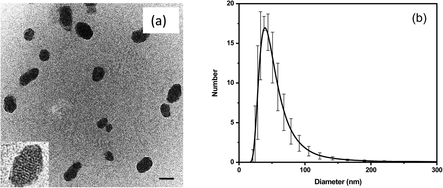 | ||
| Fig. 1 (a) A representative TEM image (scale bar is 50 nm). A 74 × 74 nm2 inset shows the mesoporous structure of the nanothermometers. (b) The particle size distribution obtained from DLS measurements. The error bar corresponds to the standard deviation obtained from five measurements. | ||
The relative brightness of the nanothermometers was calculated in MESF units (Molecules of Equivalent Soluble Fluorochrome), a standard method used in flow cytometry. This measure is robust and instrument independent. Specifically, we calculate the relative brightness of the nanothermometers with respect to the brightness of a single molecule of free rhodamine 6G and B dyes (the same molecules used for encapsulation), see ref. 68, 72, 73 and Section 2 of the ESI.† Concentrations of R6G and RhB in a 50 nm particle were found to be 1.80 mM and 1.66 mM, respectively. The relative brightness of each 50 nm particle is equivalent to that of 150 R6G and 1700 RhB. It makes the particles ultrabright as defined in ref. 68 (brighter than similar size particles made of quantum dots, the other brightest fluorescent particles). The actual number of encapsulated dye molecules per 50 nm particle is 710 R6G and 650 RhB, see the ESI† for calculation details.
The dye concentrations inside particles are sufficiently high to allow dye molecules to interact with each other through the Förster resonance energy transfer (FRET). To demonstrate it, we assume equal spreading between the dye molecules (which is a reasonable assumption, see ref. 68), a DFT pore size of 3.8 nm, and an available pore volume of 0.75 cm3 g−1.74,75 This results in an average distance between molecules of ∼5 nm. This is sufficiently small to observe a rather efficient FRET between these two dyes. This can be seen in both theory and experiment. Calculation of the FRET distance (Section 3 of the ESI†) gives the value of R0 = 8 nm. Using the calculated average distance, r = 5 nm, between the dye molecules inside the particles and from the FRET efficiency formula, E = (1 + (r/R0)6)−1, one can obtain a FRET efficiency of 94%. This implies that one can excite both fluorescent dyes with a single excitation wavelength. This property is paramount to the task of getting quantitative measurements from these particles as sensors (see the later explanation for more details).
The experimental presence of FRET can be seen in the excitation–emission matrixes shown in Fig. 2a for nanothermometers and in Fig. 2b for free dyes dissolved in water but in the same relative concentration as in nanothermometers. Note that a heavy dilution of free dyes is necessary because the dyes in water would be heavily dimerized if we use concentrations equal to the ones inside nanothermometers, which would result in fluorescence quenching.74,76–78 Comparing Fig. 2a and b, one can see the presence of FRET. For example, when the excitation wavelength is within 480–510 nm (the absorption is mainly by R6G and almost no absorption by RB), the emission is spread almost equally between fluorescence coming from R6G and RB for nanothermometers, Fig. 2a. In the case of the same proportion of the dyes mixed in water, almost the entire emission comes from R6G, with no energy transfer to RB, Fig. 2b. When the excitation is shifted to 550 nm, which is the primary absorbance of RB, both cases demonstrate fluorescence of RB. All these features are characteristics of FRET. It is useful to note that emission maxima of 550 nm for R6G and 575 nm for RhB were observed for either free dyes or dye mixture dissolved in water. When encapsulated inside the nanoporous silica particles, the emission maxima are slightly blue-shifted to 545 nm for R6G and 573 nm for RB (Fig. S3†).
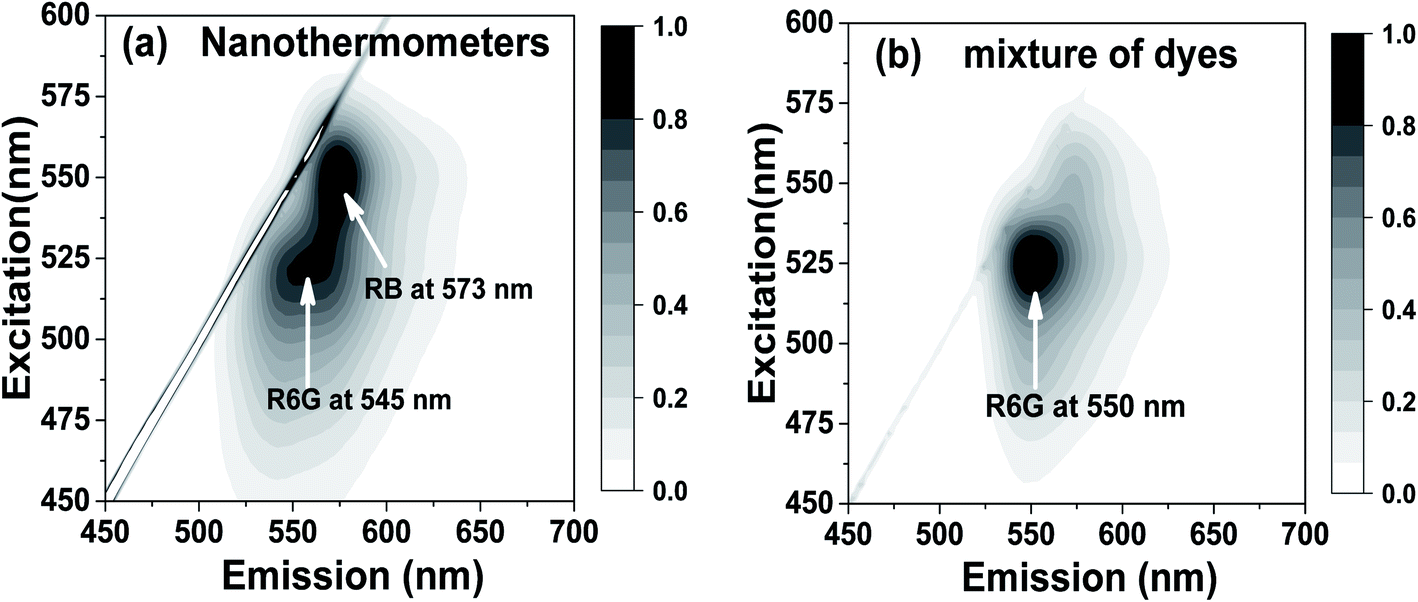 | ||
| Fig. 2 Emission and excitation matrices of (a) nanothermometers and (b) free dyes in water in the same proportions as those inside the nanothermometers but heavily dissolved (0.10 μM R6G and 0.09 μM RB, the proportion is similar to that inside the nanothermometers). Both matrices are recorded at room temperature. | ||
The temperature dependence of fluorescence was first studied for water solutions of individual dyes involved in this study. Concentrations of 0.10 μM R6G and 0.09 μM RB, and a mixture of these two dyes with the same concentrations were investigated. These small concentrations were chosen to avoid any noticeable dimerization (it can be seen by measuring the broadening of absorbance spectra, see for example, ref. 68 and 79). The temperature dependence of R6G and RB dyes is shown in Fig. 3a. One can see that RB demonstrates a strong temperature dependence (note that the excitation wavelength used here for this dye was 488 nm to obtain a detectable fluorescence spectrum), whereas R6G does not. Unlike R6G, the structure of rhodamine B is not that rigid. This leads to the reduction of the fluorescence lifetime of the dye with the increase of temperature, and the reduction of the quantum yield. This results in a decrease of fluorescence intensity with the rise of temperature. However, in the case of rhodamine 6G molecule, the structure is relatively rigid, and hence, we do not see a noticeable change in the fluorescence intensity when changing temperature. These results are in good agreement with previously reported measurements.80Fig. 3b shows the temperature dependence of the dye mix (the same proportion as that inside the nanothermometers) when excited at 488 nm. One sees no temperature dependence, and the fluorescence spectrum is essentially the one coming from R6G (in agreement with Fig. 2b). A 350 pM dispersion of nanothermometers in water was studied for temperature dependence. Fig. 3c shows the fluorescence spectra of nanothermometers excited at 488 nm at different temperatures. In contrast to the mix of R6G and RB in water, the fluorescence of nanothermometers demonstrates a strong dependence on temperature.
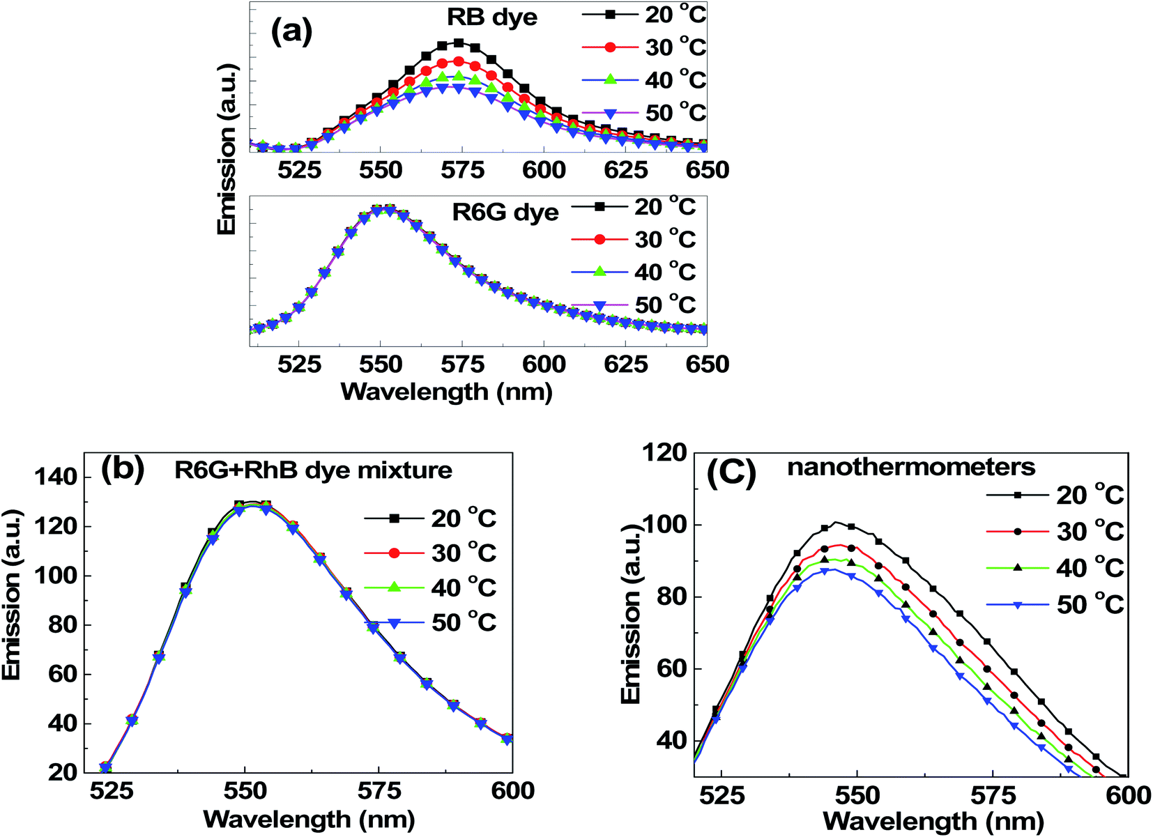 | ||
| Fig. 3 Fluorescence spectra upon excitation at 488 nm at different temperatures for (a) 0.1 μM R6G dye, 0.09 μM RB dye, (b) a mix of 0.1 μM R6G and 0.09 μM RB dyes, and (c) nanothermometers. | ||
To measure temperature using nanothermometers and also ensure independence from the intensity of the excitation source, one needs to use the ratio of fluorescence intensities at two different wavelengths, one that is strongly dependent on temperature and the other that is not (sensing and reference, respectively).34 This strategy was used in the ratiometric laser-induced fluorescence technique (LIFT), in which two fluorescent dyes were excited with two different wavelengths to measure temperature. Here we use just one excitation wavelength. The ratio of intensities was used to eliminate the effect of the fluctuation of illuminating light intensity (including fluctuation in the background noise from the excitation light source). In the case of the particles, this ratio does not depend on particle concentration (see ESI Fig. S5†) nor on the intensity of excitation light (Fig. S6†). This is a necessity for the development of a sensor, because it is virtually impossible to provide the same ratio of two excitation lights in optically inhomogeneous media (refractive index depends on wavelength), which is a typical case for many applications.
To ensure the best signal-to-noise ratio of nanothermometers, one should choose the optimal wavelengths for the temperature dependent ratio. An example of simply using the maximum fluorescence intensities of each individual dye (545 nm to 573 nm) is analyzed in the ESI (Section 6).† However, it does not necessarily give the best signal-to-noise ratio, and consequently, the minimum uncertainty in the temperature measurements. To find the best wavelengths, which would provide the minimum uncertainty in the definition of temperature, we calculated the uncertainty in the definition of temperature for all reasonably possible ratios in the emitted wavelength range. Fig. 4 shows the matrices of the uncertainty in temperature measurements for different ratios of the emission wavelengths. The temperature uncertainty was calculated based on 40 measurements. It was carried out for three representative temperatures: 20, 35 and 50 °C, as shown in Fig. 4a–c, respectively. One can see that the ratio of the intensities taken at 530 nm and 580 nm exhibits the least uncertainty in the temperature measurements of ∼1.1 °C for all considered temperatures (the time of fluorescence signal collection was 100 ms). This is noticeably better than the uncertainty measured by using non-optimized wavelengths (545 nm to 573 nm), which was more than 1.8 °C, Fig. S8.†
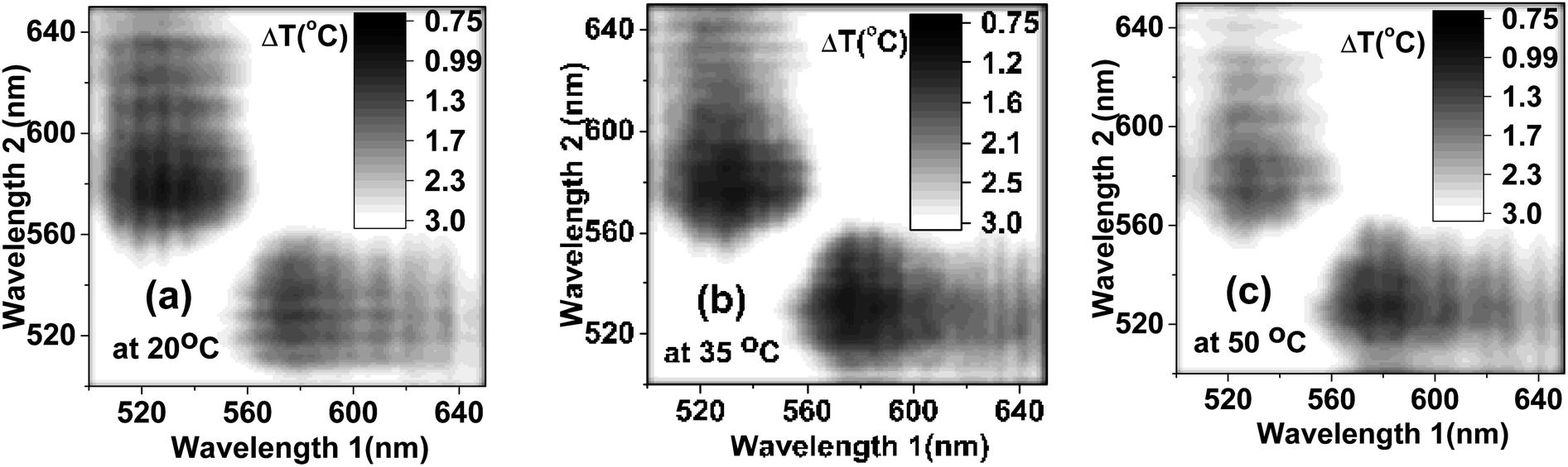 | ||
| Fig. 4 The uncertainty in temperature measured for the ratio of intensities at various wavelengths measured at (a) 20 °C, (b) 35 °C and (c) 50 °C. | ||
Fig. 5a shows the temperature response of the ratio taken and the optimal wavelengths. The calculation of temperature sensitivity shows that it is equal to 1.0%/K. It should be noted that the standard deviation of the ratio of intensities, and consequently, the uncertainty in the temperature measurements, can be decreased by increasing the time of measurements. The longer the measurement time, the lesser the uncertainty of the measurements (before one reaches a threshold limit that varies for different detectors). For example, deviations and uncertainties shown in Fig. 5a were found when the time of fluorescence signal collection Δt = 100 ms. By increasing the averaging time of the instrument, the uncertainty can be decreased. Fig. 5b shows an example of such a decrease when the temperature is fixed at T = 20 °C. One can see about 2 times improvement compared to the non-optimal ratio shown in Fig. S7.† The uncertainty in temperature measurement drops to 0.4 °C when the averaging time, Δt, is increased to 600 ms, and it further reduces to 0.35 °C when the averaging time is 1 s.
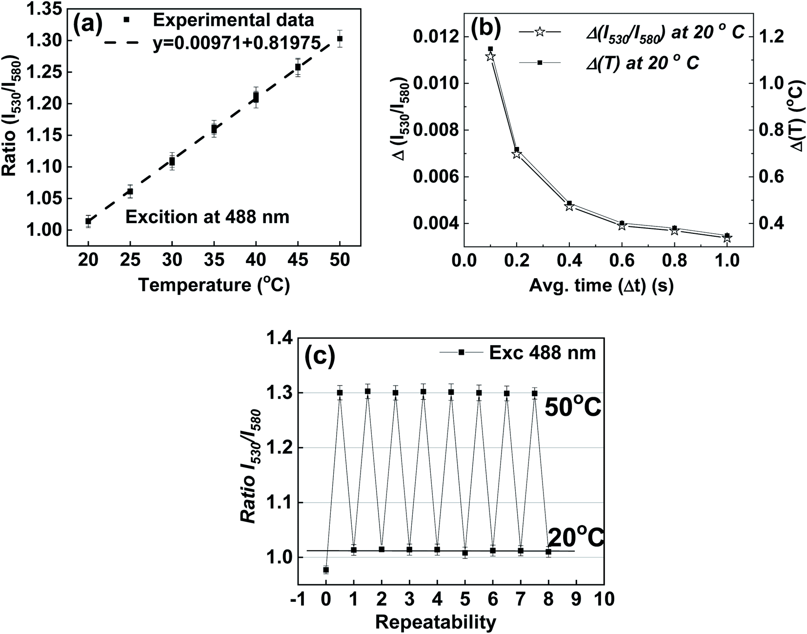 | ||
| Fig. 5 Temperature characteristics of nanothermometers. (a) Temperature dependence of the ratio of fluorescence intensities for nanothermometers with R6G and RhB dyes encapsulated. The time of averaging for each fluorescence spectral pixel Δt = 100 ms. (b) The dependence of the uncertainty of the ratio of intensities on the time of averaging for each spectral fluorescence pixel and the corresponding uncertainty in the temperature measurement. (c) Stability of the nanothermometers measured up to ten full thermal cycles between 20 °C and 50 °C. | ||
Another essential characteristic of a sensor is its repeatability with respect to multiple changes of temperature. Results of measurements of 8 full thermal cycles between 20 °C and 50 °C are shown in Fig. 5c. One can see the good stability of the synthesized nanothermometers. One can see the synthesized nanothermometers' adequate stability in terms of no change of temperature readings after each cycle, all within the range of uncertainty of the measured fluorescence ratio. (A similar result was found for the non-optimal wavelengths used to calculate the intensity ratios, Fig. S8.†) It is interesting to note a particular behavior of the first measurement (zero cycle); this ratio shows a substantial deviation from all subsequent measurements. This behavior was observed in all experiments, and therefore, it deserves particular investigation. Using atomic force microscopy (AFM) to measure the physical sizes of the same particles during the thermal cycles, we found that the particles increase their physical size 10–20% after the first heating cycle, see the ESI† (Section 7) for details. This increase is attributed to an internal restructuring of the silica matrix, which is quite a well-known process associated with the decrease of the number of silicon hydroxyl groups during the condensation of the silica matrix from silicic acid.81,82 This increase in size leads to a change in the distance between the encapsulated dye molecules, and consequently, changes the efficiency of FRET. Fortunately, after that initial thermal cycle, the silica matrix of nanothermometers is quenched, and the fluorescence behavior of nanothermometers becomes stable.
Now we demonstrate the use of nanothermometers to measure 3D temperature distribution in a hydrogel prepared as explained in the Methods section. Because the optical paths of the microscope used to measure the 3D temperature distribution are different from the ones used in the spectrometer, it was plausible to re-test temperature calibration of nanothermometers (see Section 8 of the ESI†).
To create a nontrivial temperature distribution, one end of a heated copper wire of 400 μm diameter was immersed vertically in the hydrogel. The other end of the wire was attached to a soldering rod that serves as a heating source. Fig. 6a shows the results of COMSOL finite element calculations of the temperature distribution of such a system. Equations of thermal diffusion and convection were solved in the fixed boundary conditions, see the ESI† for more details. Because the viscosity of the hydrogel is not a well-defined parameter, it was treated as a free parameter. The vertical and horizontal cross-sections of the temperature distributions are also shown for 4 different viscosities of the hydrogel: 1, 5, 10, and 20 times the viscosity of water. Fig. 6b shows a 3-D stack of 2D maps of temperature distribution measured as described in the Methods section. Fig. 6c demonstrates a comparison between experimental measurements and model simulations for a particular viscosity of the hydrogel, that is, 5× the viscosity of water. This viscosity was found to be a reasonable match, see the radial and vertical distributions of temperature shown in Fig. 6d and e, respectively.
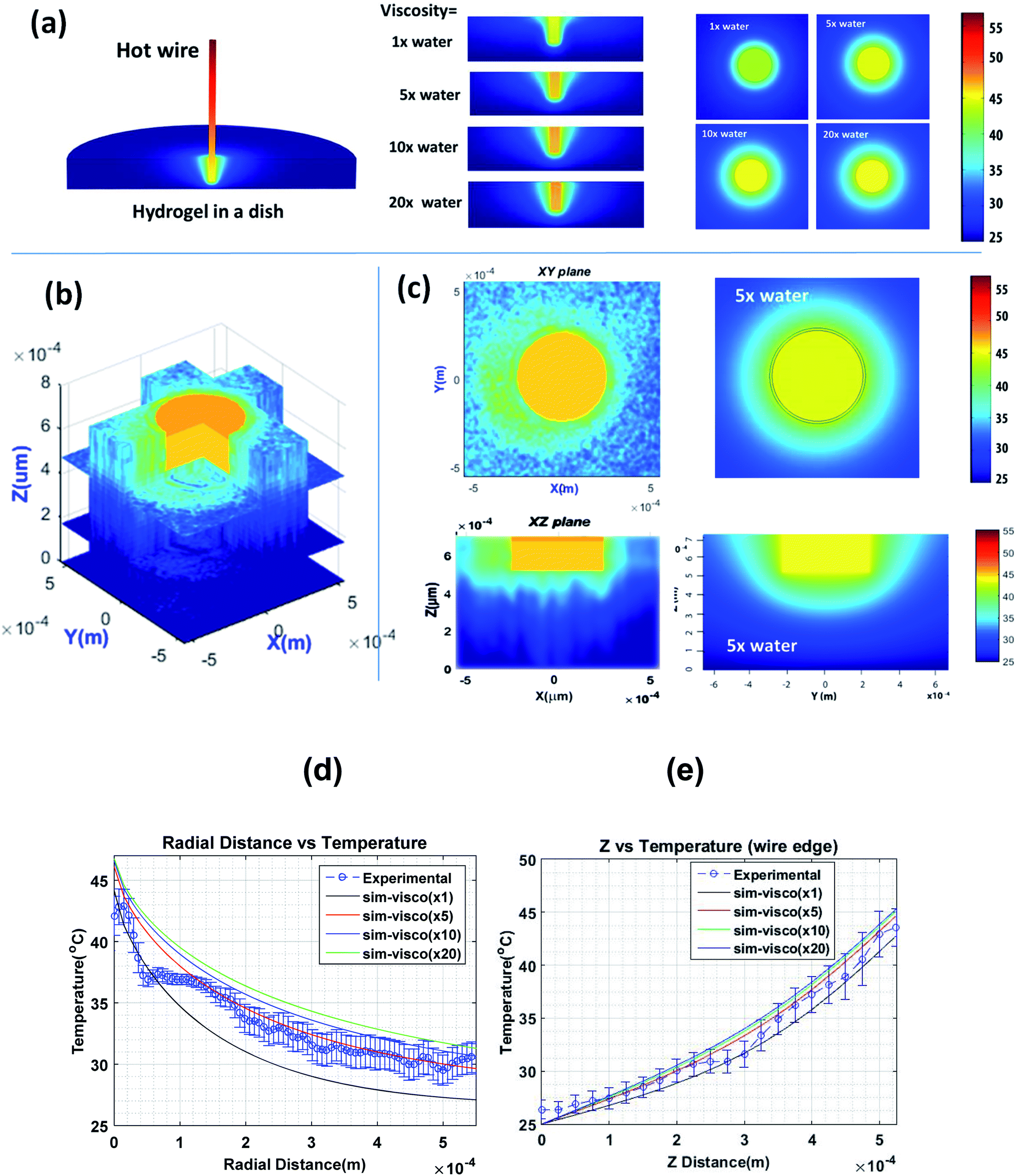 | ||
| Fig. 6 3D temperature distribution of a heated wire in a hydrogel (a) simulated with a stationary numerical model solution; different viscosities of the hydrogel are considered, (b) 3D experimental data, (c) visual comparison of the experimental data and measurement, (d) averaged radial distribution of the measured temperature (at the height of the rod apex) compared with model solutions, (e) averaged vertical distribution of the measured temperature compared with model solutions. The error bars in (d) and (e) are the variabilities (one standard deviation) of temperature measured for the angle averaging. | ||
When comparing the model and experimental data, it should be noted that the COMSOL model is stationary, which implies that it can be treated as an average for a large number of possible variations of temperature distribution in time because of convection, evaporation, and the difficulty of keeping constant the temperature boundary conditions for an extended period of time. Second, the gel viscosity might be spatially heterogeneous because of difficulties in homogenizing the hydrogel with water down to the micron scale. The asymmetry of temperature distribution could be explained by those factors. A columnar structure of the temperature distribution (in the vertical direction) seen in Fig. 6c is expected due to convection (which did not reach its equilibrium state due to the finite time of the experiment) and rather limited vertical resolution of the objective used in the measurements (∼100 μm).
One of the unique features of the described nanothermometers is their fluorescence brightness. It even allows easy imaging of single nanothermometers. Therefore, we can formulate a highly challenging question of the minimum number of nanothermometers/nanoparticles needed to reach a desirable level of accuracy of the measurements of temperature. Obviously, it is also a question of the time of measurements. According to the ergodic hypothesis, the temperature can be measured by averaging on the ensemble in either space or time.
Fig. 7 shows typical images of nanoparticles/nanothermometers adhered to a glass surface in water obtained with the exposure of 70 ms. Both spectral bands are shown: 530 nm (right image, the filter bandwidth is 30 nm) and 580 nm (left image, the filter bandwidth is 25 nm). Because particles have different optical sizes, it is clear that we are dealing with not only single nanoparticles but also small aggregates. Hereafter, we will not distinguish it in our temperature measurements (though we were trying to consider what looks like single nanoparticles, not obvious clusters, based on either their shape or brightness).
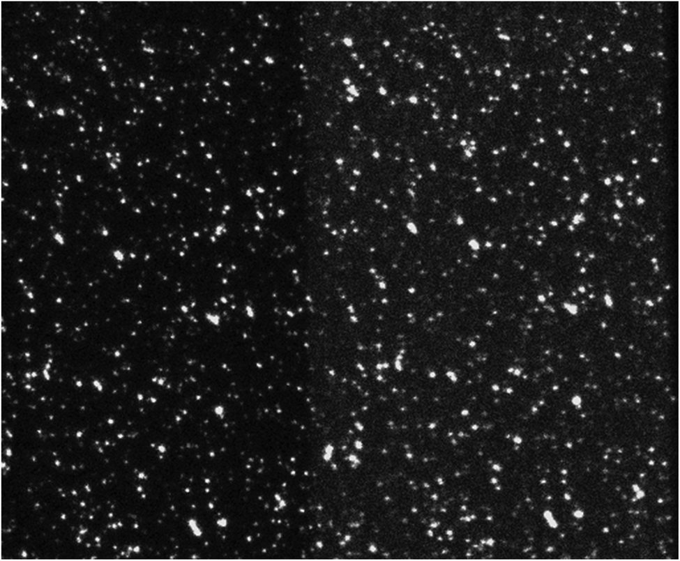 | ||
| Fig. 7 Typical fluorescence images obtained with the exposure of 70 ms of nanoparticles/nanothermometers adhered to a glass surface in water. Both spectral bands are shown: 530 nm (right image) and 580 nm (left image). The vertical scale is 65 microns. | ||
The temperature calibration was performed similarly to the bulk calibration. A linear dependence of the ratio of fluorescence intensities at 530 nm and 580 nm on the temperature was observed for the temperature ranging between 25 and 45 °C. The following formula to calculate the temperature as a function of ratio was obtained: temperature = 0.0156 × ratio + 0.340. To calculate the ratio of the fluorescence intensities for calibration, we use the fluorescence signal received from an area of 200 × 200 pixel2 and collected for 20 s (∼300 frames with an exposure of 70 ms each).
As was described in the Methods section, one can use two different methods to find the temperature (the ratio of two fluorescence intensities). In one method, the fluorescence intensity is calculated for a definite area. In the second method, the ratio is calculated for each individual particle. If the fluorescence spectra were exactly the same for each pixel/particle, then there would be no difference between these two methods. In reality, the spectra of individual particles can be slightly different. In addition, it is very important to properly subtract the background. Therefore, we consider these two methods separately.
To find the fluorescence intensity of the background, we use the dark areas between the particles as a representative value of the background (see specific examples in ESI Fig. S14†). There are also two different ways to subtract this background. In one way, we approximated the background intensity as a two-dimensional polynomial function of each pixel position. In the other way, we use the average of the background within the region of interest, which is calculated as the average value of all background intensities within that area.
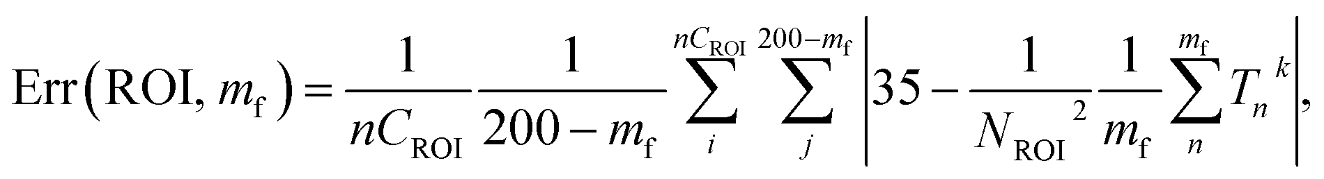
Fig. 8 shows the error of the temperature measurement when using single particles. Specifically, the deviation of the average calibrated 35 °C is plotted. This error is calculated as follows
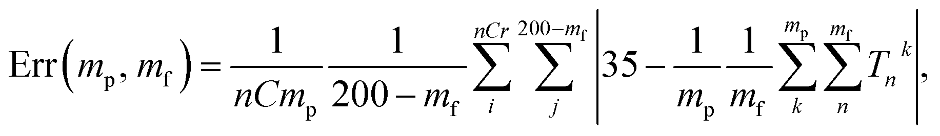 | (1) |
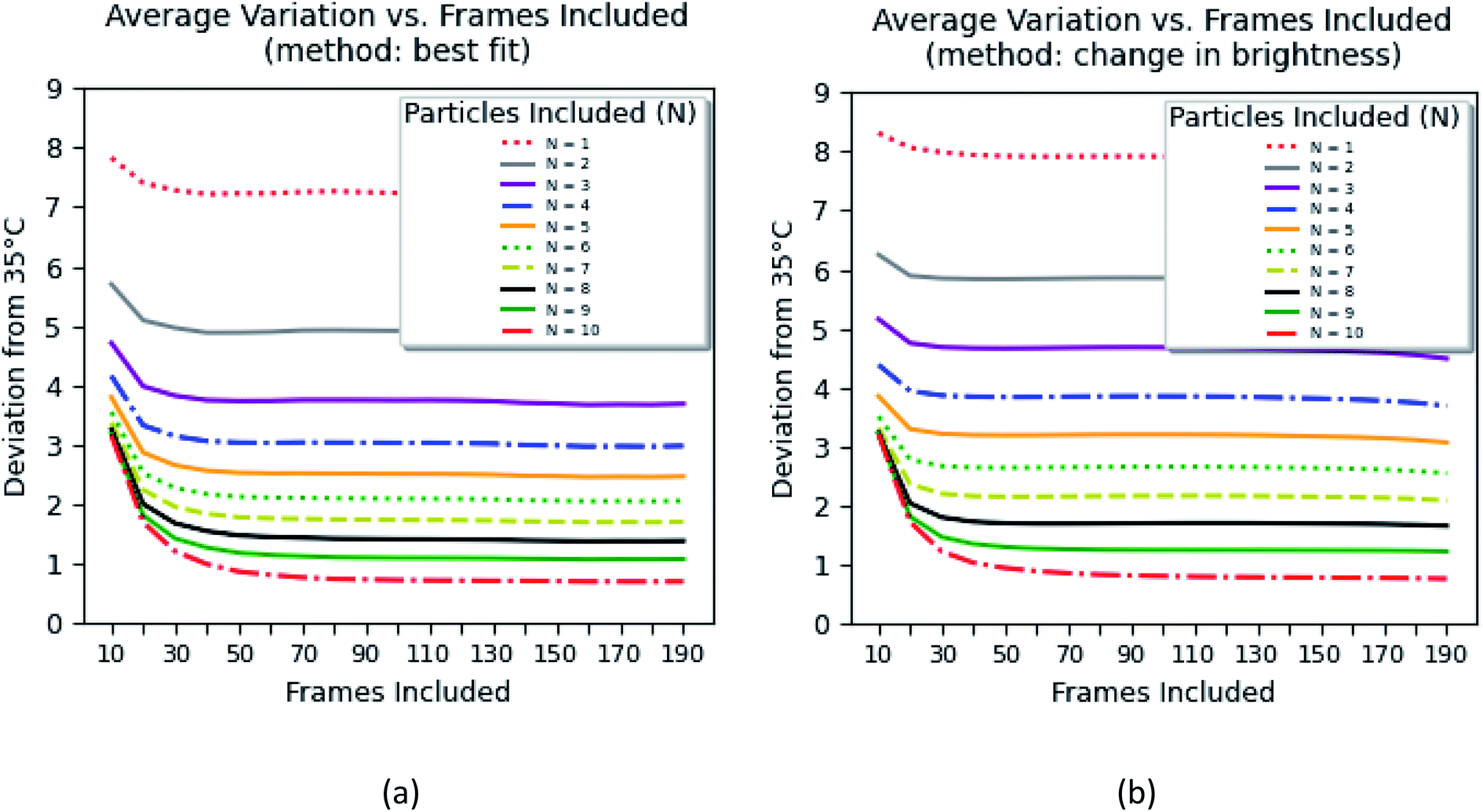 | ||
| Fig. 8 The average error of measurements of 35 °C using 1–10 nanothermometers while measuring the fluorescence signal between 700 ms (10 frames) and 14 s (200 frames). Two different methods of background subtraction were used: (a) the best fit using a polynomial function and (b) average background calculated within the region of interest (around each particle). | ||
The errors were calculated for the number of particles ranging between 1 and 10 and the time of the measurements between 70 ms and 14 s. Two methods of background subtraction were used. The best fit using a polynomial function (Fig. 8a) shows slightly better results compared to the average background calculated within the region of interest (Fig. 8b). One can see that the average error crosses the threshold of 2 °C when 7–8 particles are used to measure the temperature for 1.4–2.0 s.
The method based on the measurement of fluorescence intensities of a region of interest (ROI) is simpler because it does not require identification of individual particles. The error of the measurement can now be found using eqn (2).
 | (2) |
The results of these measurements are shown in Fig. 9. The method that uses the best fit with a polynomial function to describe the background (Fig. 9a) shows slightly less error in the definition of temperature than the method that uses the average background calculated within the region of interest (Fig. 9b).
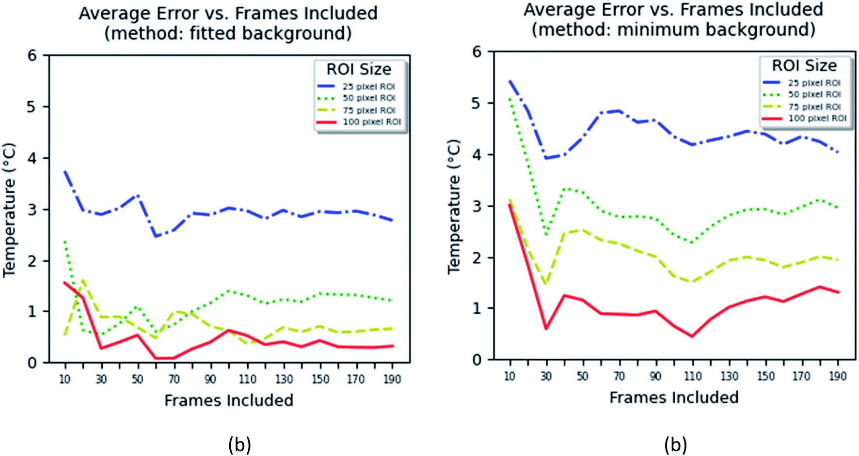 | ||
| Fig. 9 The average error of measurements of 35 °C using the ratio of the fluorescence intensities averaged over an area (region of interest), while measuring the fluorescence signal between 700 ms (10 frames) and 14 s (200 frames). Two different methods of background subtraction were used: (a) the best fit using a polynomial function and (b) the average background calculated within and around the region of interest. | ||
One can see from Fig. 9 that one can obtain the error of temperature measurements of 2 °C when the area of between 25 × 25 and 50 × 50 pixel2 is used and the time of measurements is >0.7 s for the fitted background method, and >75 × 75 pixel2 and >1.5 s for the minimum background method. Because the method is based on the calculation of the average area, it is not possible to unambiguously relate it to the number of particles. Nevertheless, estimation shows that an area of 25 × 25 pixel2 contains 4–5 particles in average, whereas an area of 50 × 50 pixel2 contains 8–10 particles. Thus, one can conclude that both methods based on either individual counting of nanoparticles or aerial averaging give approximately the same result.
It would be interesting to compare the obtained results with previously reported studies on nanothermometry. However, nanothermometry experiments are traditionally executed using bulk volumes of particles with the assumption that sensor homogeneity is valid for temperature analysis at all length scales. In recent years, nanosensors have been developed with big improvements in accuracy, achieving better than 0.1 K bulk measurement error with calibrations being performed under static and macroscale conditions.6 The ultrabright nature of our particles enables visualization of discrete sensors and can provide a more authentic representation of temperature distributions at the nanoscale levels. From single photon microscopy studies of individual particles, we see an increased temperature variation between particles at the nanoscale. This work highlights sensor heterogeneity as a critical factor when evaluating nanothermometry data as well as the importance of considering temporal elements when calculating accuracy.
Conclusions
Understanding the temperature distributions down to the nanoscale is of both fundamental and applied importance. We report on the synthesis and study of ultrabright fluorescent ratiometric nanothermometers. The ultrabright nature of the synthesized sensors allowed us for the first time to profile 3D distributions of temperature and perform the measurements down to individual nanoparticles.Methods
Materials
Tetraethyl orthosilicate (TEOS, Aldrich), cetyltrimethylammonium chloride (CTAC, 25% aqueous solution, Aldrich), triethanolamine (TEA, Aldrich), rhodamine 6G (R6G), and rhodamine B (RB) (Exciton Inc.) were used in this study without any purification. Ultrapure deionized water from a Milli-Q ultrapure system was used for all synthesis, dialysis, and storage steps. Dialysis membranes with a molecular weight cutoff of 14 kDa (spectra/pore regenerated cellulose) were used in all dialysis steps.Synthesis procedure
A relative molar composition of 1![[thin space (1/6-em)]](https://www.rsc.org/images/entities/char_2009.gif) :0.25:13:174 TEOS/CTAC/TEA/H2O was used for the synthesis of nanoparticles. The molar concentrations of R6G and RB were 0.008 M for both dyes. In a typical synthesis to obtain the dye-doped nanoparticles, TEOS (0.5 g) and TEA (4 g) were taken in a 50 mL glass vial without mixing and heated for 3 h at 90 °C. A solution of R6G (0.0265 g), RB (0.0265 g), 25% aqueous solution of CTAC (0.76 g), and distilled water (6.91 g) was kept at 60 °C under stirring for 1 hour. The two solutions were mixed in a 60 mL polypropylene bottle and stirred at room temperature for 3 hours. The reaction mixture was then dialyzed against DI water until no fluorescence was observed in the dialyzing solution.
:0.25:13:174 TEOS/CTAC/TEA/H2O was used for the synthesis of nanoparticles. The molar concentrations of R6G and RB were 0.008 M for both dyes. In a typical synthesis to obtain the dye-doped nanoparticles, TEOS (0.5 g) and TEA (4 g) were taken in a 50 mL glass vial without mixing and heated for 3 h at 90 °C. A solution of R6G (0.0265 g), RB (0.0265 g), 25% aqueous solution of CTAC (0.76 g), and distilled water (6.91 g) was kept at 60 °C under stirring for 1 hour. The two solutions were mixed in a 60 mL polypropylene bottle and stirred at room temperature for 3 hours. The reaction mixture was then dialyzed against DI water until no fluorescence was observed in the dialyzing solution.
Temperature measurements and calibration procedures
The measurements were performed in a hydrogel medium (5% w/v of Water-gel in water, Steve Spangler, Inc). The absence of any autofluorescence of the hydrogel was confirmed for the entire wavelength range used in measuring temperature. The nanothermometers were introduced into the prepared hydrogel by simple mechanical mixing. An inverted Nikon TE 2000U microscope with a 4× objective was used to collect optical fluorescence images (spherical aberration was minimal when using this objective, which was verified by focusing on samples of different heights). Single-particle measurements were performed using the same setup but with a 100× 1.4 NA oil-immersion objective.A heating stage connected to a temperature controller (Lakeshore 331) was mounted on the table of the inverted microscope. The hydrogel–nanothermometer sample was placed in a specifically designed dish and was placed on the heating stage. To monitor the temperature of surfaces, an IR camera (Therm-App) was used; the bulk temperature was measured using a Lakeshore thermocouple. 488 nm excitation light was supplied from a Fluorolog-3 (Horiba) spectrometer through an optical fiber attachment (by Horiba). Two fluorescence images were collected for each area simultaneously with an OptoSplit II LS Image Splitter (Cairn Research Ltd) and an Andor 897 single-photon camera (by Andor). The two fluorescence images were taken by using bandpass filters (Chroma Technology, Inc.) centered at 530 nm and 580 nm wavelengths which correspond to the optimum for the ratiometric measurements of temperature, see later for details. The ratio of the intensities of these two images gives the value of temperature.
The calibration plot (temperature versus the fluorescence intensity ratio) of nanothermometers was obtained using 2D fluorescence images of particles dispersed in the hydrogel of equilibrated temperature (within the temperature range of interest, 20–50 °C). Note that the bulk measurement of fluorescence as a function of temperature was conducted using particles in a cuvette in a spectrometer, see the next sub-section. 3D temperature distributions were created by introducing a hot wire into the gel, see the Results and discussion section. To obtain a 3D image, the nanothermometers–hydrogel sample was placed in a specifically designed plastic Petri-dish (2 cm diameter and 0.5 cm height) with a glass slide attached (glass was used to improve heat conduction and to improve optical transparency). Measurements of 3D temperature distributions were carried out by collecting and processing 2D stages of temperature distributions (performed with the help of Matlab).
The temperature calibration and single particle measurements were performed in a similar way with the same Nikon microscope but by using a 100× 1.4 N.A. oil-immersion objective. The sensitivity was recalibrated to exclude any optic-specific aberrations. Specifically, the fluorescence images (the fluorescence intensity for each spectral band) were averaged for the maximum number of particles (area) and the maximum time of the measurements. The ratio of the averaged intensities (after subtraction of the background) was assigned to the calibrated temperature. Two separate methods to find the fluorescence intensities were explored. In one method, the total intensity from a region of interest was calculated for each spectral band. And the ratio (after subtraction of the background) was found. In the second method, the ratio was found for each clearly identifiable particle. The background was identified as the lowest intensity away from individual particles. The subtraction of this background was explored in two different ways. In the first way, the background was approximated using a polynomial 2D function across the image, and then the approximated function was used as the background to subtract. In the second way, the background was directly measured around each particle.
Characterization
The particle size distributions were measured using a dynamic light scattering (DLS) Zetasizer-nano-ZS (Malvern, MA) equipped with a standard 35 mW diode laser and an avalanche photodiode detector. The effective and most probable diameters were measured three times. As an example, 0.25 mL of stock solution was diluted to 3 mL with deionized water and ultrasonicated for 5 min prior to measurements.Transmission electron microscopy (TEM) images of the particles were recorded on a TEM 2010 electron microscope (JEOL) at an acceleration voltage of 200 kV. The samples were prepared by dispersing the particles in water at room temperature. A few drops of this dispersion were placed on a holey carbon-coated mesh and dried at room temperature. Fluorescence spectrophotometers Cary Eclipse (Agilent) and Fluorolog-3 (Horiba) were used. The absorbance was measured by means of a Cary-60 UV-VIS spectrophotometer (Agilent). The temperature of the solution was controlled and measured with a Quantum Northwest TC 125 controller equipped with a thermocouple.
A Bioscope Catalyst (Bruker Nano/Veeco, Inc.) AFM with a Nanoscope V controller and Nanoscope 8.1 software was used here to record AFM images of the particles. A standard cantilever holder for operation in air and ScanAsyst Air probes (Veeco/Bruker instruments) with a typical tip radius of 2–3 nm were used. All measurements were performed in air at the temperature of 24–45 °C and relative humidity of 40–60%. To control the temperature of the glass substrate, a Veeco/LakeShore 331S temperature control unit with a heating stage was used. For all experiments, particles were dispersed on a pre-cleaned glass substrate (glass substrates were cleaned with ethyl alcohol using an ultrasonic bath after it was rinsed with DI water (in the ultrasonic bath) and dried under ultrapure nitrogen). For single-particle imaging, a glass slide was used. The particles were allowed to electrostatically stick to the negatively charged glass before imaging. The imaging was performed in water. The water droplet was covered with a cover slip to prevent water evaporation and to decrease the convection.
Simulations
Theoretical simulations of 3D temperature distributions were obtained with the help of COMSOL Multiphysics (v.5.1). Equations of thermal diffusion and convection were solved with the fixed boundary conditions. A stationary solution was found, see the ESI† for more details.Author contributions
V. K., I. S., and S. P. developed the synthesis. V. K. and S. A. M. A. P. performed the synthesis. V. K. performed the SEM, DLS, optical characterization of nanothermometers, bulk temperature calibration, 3D measurements of temperature distribution, and COMSOL simulations. M. E. D. carried out the AFM measurements. I. S. and B. P. conducted the single-photon imaging of nanothermometers. B. M., B. P. and I. S. performed the processing of single-photon imaging of nanothermometers. I. S. designed the entire study and provided financial support. The manuscript was written by I. S. with contributions from V. K and B. P. All authors have given approval to the final version of the manuscript.Conflicts of interest
V. K., I. S., and S. P. are inventors on a patent on ultrabright fluorescent nanothermometers. The other authors have no conflicts of interest to declare.Acknowledgements
This work has been supported by NSF grants CBET 1605405, 2110757 and CMMI 1937373 (I. S.).References
- A. A. Alaulamie, S. Baral, S. C. Johnson and H. H. Richardson, Small, 2017, 13, 1601989 CrossRef PubMed.
- C. D. S. Brites, P. P. Lima, N. J. O. Silva, A. Millan, V. S. Amaral, F. Palacio and L. D. Carlos, Nanoscale, 2012, 4, 4799–4829 RSC.
- K. Azar, J. R. Benson and V. P. Manno, Liquid-Crystal Imaging for Temperature-Measurement of Electronic Devices, 1991 Search PubMed.
- D. J. Farina, J. Electron. Cool. Therm. Control, 1995, 1, 10–15 Search PubMed.
- G. Baffou, H. Rigneault, D. Marguet and L. Jullien, Nat. Methods, 2014, 11, 899–901 CrossRef CAS PubMed.
- G. Kucsko, P. C. Maurer, N. Y. Yao, M. Kubo, H. J. Noh, P. K. Lo, H. Park and M. D. Lukin, Nature, 2013, 500, 54–58 CrossRef CAS PubMed.
- X. Huang, I. H. El-Sayed, W. Qian and M. A. El-Sayed, J. Am. Chem. Soc., 2006, 128, 2115–2120 CrossRef CAS.
- A. Jordan, P. Wust, H. Fahling, W. John, A. Hinz and R. Felix, Int. J. Hyperthermia, 1993, 9, 51–68 CrossRef CAS PubMed.
- A. M. Gobin, M. H. Lee, N. J. Halas, W. D. James, R. A. Drezek and J. L. West, Nano Lett., 2007, 7, 1929–1934 CrossRef CAS.
- J. J. Shah, M. Gaitan and J. Geist, Anal. Chem., 2009, 81, 8260–8263 CrossRef CAS PubMed.
- S. Arai, S.-C. Lee, D. Zhai, M. Suzuki and Y. T. Chang, Sci. Rep., 2014, 4, 6701 CrossRef CAS PubMed.
- A. Soleilhac, M. Girod, P. Dugourd, B. Burdin, J. Parvole, P.-Y. Dugas, F. Bayard, E. Lacôte, E. Bourgeat-Lami and R. Antoine, Langmuir, 2016, 32, 4052–4058 CrossRef CAS PubMed.
- R. Kumar, I. Roy, T. Y. Ohulchanskyy, L. N. Goswami, A. C. Bonoiu, E. J. Bergey, K. M. Tramposch, A. Maitra and P. N. Prasad, ACS Nano, 2008, 2, 449–456 CrossRef CAS PubMed.
- S. Uchiyama, T. Tsuji, K. Ikado, A. Yoshida, K. Kawamoto, T. Hayashi and N. Inada, Analyst, 2015, 140, 4498–4506 RSC.
- N. G. Zhegalova, A. Aydt, S. T. Wang and M. Y. Berezin, Molecular thermometers for potential applications in thermal ablation procedures, Proc. SPIE 8596, Reporters, Markers, Dyes, Nanoparticles, and Molecular Probes for Biomedical Applications, 2013, vol. 85960I Search PubMed.
- K. Okabe, N. Inada, C. Gota, Y. Harada, T. Funatsu and S. Uchiyama, Nat. Commun., 2012, 3, 705 CrossRef PubMed.
- Y. Takei, S. Arai, A. Murata, M. Takabayashi, K. Oyama, S. Ishiwata, S. Takeoka and M. Suzuki, ACS Nano, 2014, 8, 198–206 CrossRef CAS PubMed.
- F. Vetrone, R. Naccache, A. Zamarrón, A. Juarranz de la Fuente, F. Sanz-Rodríguez, L. Martinez Maestro, E. Martín Rodriguez, D. Jaque, J. García Solé and J. A. Capobianco, ACS Nano, 2010, 4, 3254–3258 CrossRef CAS PubMed.
- Y. Yang, W. Kong, H. Li, J. Liu, M. Yang, H. Huang, Y. Liu, Z. Wang, Z. Wang, T.-K. Sham, J. Zhong, C. Wang, Z. Liu, S.-T. Lee and Z. Kang, ACS Appl. Mater. Interfaces, 2015, 7(49), 27324–27330 CrossRef CAS PubMed.
- H. Liu, Y. Fan, J. Wang, Z. Song, H. Shi, R. Han, Y. Sha and Y. Jiang, Sci. Rep., 2015, 5, 14879 CrossRef CAS PubMed.
- A. Gupta, R. S. Kane and D.-A. Borca-Tasciuc, J. Appl. Phys., 2010, 108, 064901 CrossRef.
- C. Wang, L. Ling, Y. Yao and Q. Song, Nano Res., 2015, 8, 1975–1986 CrossRef CAS.
- F. Ye, C. Wu, Y. Jin, Y.-H. Chan, X. Zhang and D. T. Chiu, J. Am. Chem. Soc., 2011, 133, 8146–8149 CrossRef CAS PubMed.
- D. Jaque and F. Vetrone, Nanoscale, 2012, 4, 4301–4326 RSC.
- A. Carattino, M. Caldarola and M. Orrit, Nano Lett., 2018, 18, 874–880 CrossRef CAS PubMed.
- Y.-H. Chan and P.-J. Wu, Part. Part. Syst. Charact., 2015, 32, 11–28 CrossRef CAS.
- D. Zhao, X. Rao, J. Yu, Y. Cui, Y. Yang and G. Qian, Inorg. Chem., 2015, 54, 11193–11199 CrossRef CAS PubMed.
- H. Zhou, M. Sharma, O. Berezin, D. Zuckerman and M. Y. Berezin, ChemPhysChem, 2015, 17(1), 27–36 CrossRef PubMed.
- G. H. Darwish, J. Abouzeid and P. Karam, RSC Adv., 2016, 6, 67002–67010 RSC.
- P. Chamarthy, S. V. Garimella and S. T. Wereley, Int. J. Heat Mass Transfer, 2010, 53, 3275–3283 CrossRef CAS.
- J. Yin, C. Li, D. Wang and S. Liu, J. Phys. Chem. B, 2010, 114, 12213–12220 CrossRef CAS PubMed.
- A. E. Albers, E. M. Chan, P. M. McBride, C. M. Ajo-Franklin, B. E. Cohen and B. A. Helms, J. Am. Chem. Soc., 2012, 134, 9565–9568 CrossRef CAS PubMed.
- M. A. Chowdhury, M. Joshi and B. S. Butola, J. Eng. Fibers Fabr., 2014, 9, 107–123 Search PubMed.
- J. Sakakibara and R. J. Adrian, Exp. Fluids, 1999, 26, 7–15 CrossRef CAS.
- H. J. Kim and K. D. Kihm, J. Heat Transfer, 2002, 124, 596 CrossRef CAS.
- W. G. Bessler, F. Hildenbrand and C. Schulz, Appl. Opt., 2001, 40, 748–756 CrossRef CAS PubMed.
- H. Hu and M. M. Koochesfahani, Meas. Sci. Technol., 2006, 17, 1269–1281 CrossRef CAS.
- T. Finegan, P. E. Laibinis and T. A. Hatton, AIChE J., 2006, 52, 2727–2735 CrossRef CAS.
- T. Lee, W. G. Bessler, H. Kronemayer, C. Schulz and J. B. Jeffries, Appl. Opt., 2005, 44, 6718–6728 CrossRef CAS PubMed.
- R. Giezendanner-Thoben, U. Meier, W. Meier, J. Heinze and M. Aigner, Appl. Opt., 2005, 44, 6565–6577 CrossRef CAS PubMed.
- R. Giezendanner-Thoben, U. Meier, W. Meier and M. Aigner, Flow, Turbul. Combust., 2005, 75, 317–333 CrossRef CAS.
- H. Kronemayer, W. G. Bessler and C. Schulz, Appl. Phys. B: Lasers Opt., 2005, 81, 1071–1074 CrossRef CAS.
- V. M. Salazar, J. E. Gonzalez and L. A. Rivera, J. Heat Transfer, 2004, 126, 279–285 CrossRef CAS.
- S. Funatani, N. Fujisawa and H. Ikeda, Meas. Sci. Technol., 2004, 15, 983–990 CrossRef CAS.
- A. Omrane, F. Ossler and M. Alden, Proc. Combust. Inst., 2003, 29, 2653–2659 CrossRef.
- A. Burkert, W. Triebel, H. Stafast and J. Konig, Proc. Combust. Inst., 2003, 29, 2645–2651 CrossRef.
- J. Nygren, J. Engstrom, J. Walewski, C. F. Kaminski and M. Alden, Meas. Sci. Technol., 2001, 12, 1294–1303 CrossRef CAS.
- A. C. Edge, G. Laufer and R. H. Krauss, Appl. Opt., 2000, 39, 546–553 CrossRef CAS.
- G. Dilecce, M. Simek, M. Vigliotti and S. De Benedictis, Appl. Spectrosc., 2000, 54, 824–831 CrossRef CAS.
- M. S. Mansour, Combust. Sci. Technol., 2000, 152, 115–145 CrossRef CAS.
- J. Engstrom, J. Nygren, M. Alden and C. F. Kaminski, Opt. Lett., 2000, 25, 1469–1471 CrossRef CAS PubMed.
- U. E. Meier, D. Wolff-Gassmann and W. Stricker, Aerosp. Sci. Technol., 2000, 4, 403–414 CrossRef.
- J. P. Feist and A. L. Heyes, Proc. Inst. Mech. Eng., Part L, 2000, 214, 7–12 Search PubMed.
- T. Plessing, C. Kortschik, N. Peters, M. S. Mansour and R. K. Cheng, Proc. Combust. Inst., 2000, 28, 359–366 CrossRef CAS.
- M. Tsujishita, A. Hirano, M. Yokoo, T. Sakuraya and Y. Takeshita, JSME Int. J., Ser. B, 1999, 42, 119–126 CrossRef CAS.
- R. L. Vander Wal, P. A. Householder and T. W. Wright, Appl. Spectrosc., 1999, 53, 1251–1258 CrossRef CAS.
- W. M. Ruyten, M. S. Smith, L. L. Price and W. D. Williams, Appl. Opt., 1998, 37, 2334–2339 CrossRef CAS.
- P. F. Barker, A. M. Thomas, T. J. McIntyre and H. Rubinsztein-Dunlop, AIAA J., 1998, 36, 1055–1060 CrossRef CAS.
- P. C. Palma, T. J. McIntyre and A. F. P. Houwing, Shock Waves, 1998, 8, 275–284 CrossRef.
- Y. C. Chen and M. S. Mansour, Appl. Phys. B: Lasers Opt., 1997, 64, 599–605 CrossRef CAS.
- M. Yorozu, Y. Okada and A. Endo, Opt. Rev., 1996, 3, 293–298 CrossRef CAS.
- Y. C. Chen, N. Peters, G. A. Schneemann, N. Wruck, U. Renz and M. S. Mansour, Combust. Flame, 1996, 107, 223–244 CrossRef CAS.
- J. M. Seitzman, R. K. Hanson, P. A. Debarber and C. F. Hess, Appl. Opt., 1994, 33, 4000–4012 CrossRef CAS PubMed.
- M. Alden, P. E. Bengtsson, N. Georgiev, C. Lofstrom, L. Martinsson and H. Neij, Ber. Bunsenges. Phys. Chem., 1993, 97, 1643–1649 CrossRef CAS.
- L. A. Melton, Ber. Bunsenges. Phys. Chem., 1993, 97, 1560–1567 CrossRef CAS.
- Y. Wu, J. Liu, J. Ma, Y. Liu, Y. Wang and D. Wu, ACS Appl. Mater. Interfaces, 2016, 8, 14396–14405 CrossRef.
- S. Santra, H. Yang, D. Dutta, J. T. Stanley, P. H. Holloway, W. Tan, B. M. Moudgil and R. A. Mericle, Chem. Commun., 2004,(24), 2810–2811, 10.1039/B411916A.
- V. Kalaparthi, S. Palantavida and I. Sokolov, J. Mater. Chem. C, 2016, 4, 2197–2210 RSC.
- S. Palantavida, B. Peng and I. Sokolov, Nanoscale, 2017, 9, 4881–4890 RSC.
- S. A. M. A. Peerzade, N. Makarova and I. Sokolov, Nanomaterials, 2020, 10(5), 905 CrossRef CAS PubMed.
- J. Zhou, B. Del Rosal, D. Jaque, S. Uchiyama and D. Jin, Nat. Methods, 2020, 17, 967–980 CrossRef CAS PubMed.
- S. Palantavida, R. Tang, G. P. Sudlow, W. J. Akers, S. Achilefu and I. Sokolov, J. Mater. Chem. B, 2014, 2, 3107–3114 RSC.
- S. Palantavida, N. V. Guz and I. Sokolov, Part. Part. Syst. Charact., 2013, 30, 804–811 CrossRef CAS.
- E.-B. Cho, D. O. Volkov and I. Sokolov, Adv. Funct. Mater., 2011, 21, 3129–3135 CrossRef CAS.
- E. B. Cho, D. O. Volkov and I. Sokolov, Small, 2010, 6, 2314–2319 CrossRef CAS PubMed.
- E.-B. Cho, D. O. Volkov and I. Sokolov, Small, 2010, 6, 2314–2319 CrossRef CAS PubMed.
- D. O. Volkov, E.-B. Cho and I. Sokolov, Nanoscale, 2011, 3, 2036–2043 RSC.
- I. Sokolov, Y. Y. Kievsky and J. M. Kaszpurenko, Small, 2007, 3, 419–423 CrossRef CAS PubMed.
- J. R. Lakowicz, Principles of Fluorescence Spectroscopy, Springer, New York, 3rd edn, 2006 Search PubMed.
- T. Karstens and K. Kobs, J. Phys. Chem., 1980, 84, 1871–1872 CrossRef CAS.
- D. O. Volkov, J. Benson, Y. Y. Kievsky and I. Sokolov, Phys. Chem. Chem. Phys., 2010, 12, 341–344 RSC.
- S. M. Yang, I. Sokolov, N. Coombs, C. T. Kresge and G. A. Ozin, Adv. Mater., 1999, 11, 1427–1431 CrossRef CAS.
Footnotes |
| † Electronic supplementary information (ESI) available: (1) Physical dimensions of particles; (2) calculation of effective brightness of nanothermometers; (3) calculation of the Förster distance; (4) independence of temperature sensing from concentration of nanothermometers; (5) independence of temperature sensing from the intensity of the excitation light; (6) ratiometric temperature sensing example by using fluorescence maxima of individual dyes (545 nm to 573 nm); (7) change in the nanothermometer size after the initial heating; (8) temperature calibration of nanothermometers for use in 3-D temperature distribution measurements; (9) COMSOL model to calculate 3-D temperature distribution; (10) temperature measurements of nanothermometers at the single particle level. See DOI: 10.1039/d1na00449b |
| ‡ Present address: GLOBALFOUNDRIES, 1000 River Str., Essex Junction, VT 05452, USA. |
| § Present address: Center for Nano and Material Sciences, Jain University, Jakkasandra, Kanakapura, Karnataka 562112, India. |
| This journal is © The Royal Society of Chemistry 2021 |