DOI:
10.1039/D0SM01719A
(Paper)
Soft Matter, 2021,
17, 102-112
Elasticity of connected semiflexible quadrilaterals
Received
24th September 2020
, Accepted 28th October 2020
First published on 5th November 2020
Abstract
Using the positional–orientational propagator of a semiflexible filament in the weakly bending regime, we analytically calculate the probability densities associated with the fluctuating tip and the corners of a grafted system of connected quadrilaterals. We calculate closed analytic expressions for the probability densities within the framework of the worm-like chain model, which are valid in the weakly bending regime. The probability densities give the physical quantities related to the elasticity of the system such as the force–extension relation in the fixed extension ensemble, the Poisson's ratio and the average of the force exerted to a confining stiff planar wall by the fluctuating tip of the system. Our analysis reveals that the force–extension relations depend on the contour length of the system (material content), the bending stiffness (chemical nature), the geometrical angle and the number of the quadrilaterals, while the Poisson's ratio depends only on the geometrical angle and the number of the quadrilaterals, and is thus a purely geometric property of the system.
1 Introduction
Semiflexible filaments such as the cellular cytoskeletal elements (e.g., actins, microtubules, and intermediate filaments) and the genomic DNA play critical roles in many biological functions and have been subjects of intense research during the recent decades.1–34 These biofilaments take various topologies and are often confined within cellular boundaries that exert or transduce mechanical forces.35 Moreover, the study of the mechanical properties of such semiflexible filaments is important in designing new bio- and nano-materials.36 An important emerging field of research is structural DNA nanotechnology. Progress has been made in designing programmable nanoscale architectures through the self-assembly of synthetic oligonucleotides via base-pairing and other forms of intermolecular connectivity. Various topologies and spatial configurations have been designed and synthesized for various applications, from electronics and photonics to biology and nanomedicine.37–44 One way to make such DNA nanostructures is via folding and assembly of DNA molecules into various topologies, the so-called DNA origami. Defined structures can be made of DNA filaments by the arrangement of nucleotides with a sub-nanometer precision.45–55 The structural DNA nanotechnology provides us with a plethora of techniques to design and to make two dimensional and three dimensional nano-objects, which can be static or dynamic.56–69
The worm-like chain model is a commonly used model for describing the elasticity of semiflexible filaments. There are numerous studies in which elasticity of the semiflexible filaments were investigated within the framework of the worm-like chain model.30,70–76 Next to theoretical developments, many progresses have been made in experimental characterization of semiflexible filaments (polymers) in recent decades. Powerful techniques like optical tweezers, atomic force microscopy and other force methods allow us to measure the elasticity of such filaments at the single molecule (filament) level.77–85 In these experiments, the force–extension relation is typically measured by stretching or compressing the filament (polymer) by an external force applied to the filament's ends (or “tips”). The force–extension relation of a single filament in longitudinal direction gives stretching or compressing behavior of the filament while the force–extension relation in lateral direction gives the bending behavior of the filament. The force–extension relation can be obtained in two different ensembles, namely the fixed-extension ensemble, and the fixed-force ensemble.86 In the fixed-extension ensemble, the displacement of the tips is fixed and the external force fluctuates due to the thermal fluctuation of the polymer. In the fixed-force ensemble, the external force exerted on the tips of the polymer is fixed, while the displacement of the tips undergoes thermal fluctuations.
Here, we study the elasticity of structures made by longitudinally connected quadrilaterals. The work is motivated by recent developments in structural DNA nanotechnology. The quadrilaterals consist of semiflexible filaments, which can be made by DNA fragments or other semiflexible polymers. In the Section 2.1, we describe the positional–orientational propagator of a semiflexible filament in the weakly bending regime based on existing theories. In the Section 2.2, we consider a grafted quadrilateral. In the presence of thermal fluctuations, using the positional–orientational propagator, we obtain the probability density associated with the fluctuations and calculate the force–extension relation of the tip of the quadrilateral in the fixed extension ensemble in two different direction, x and y. Also, we calculate the Poisson's ratio of the structure. Furthermore, we confine the structure by a stiff planar wall and calculate the average of the fluctuating force exerted to the wall. The force is caused by a reduction in the number of configurations available to the system, which is in turn caused by the presence of the wall. In the Section 2.3, we repeat the calculations for the case of two longitudinally connected quadrilaterals. In Section 2.4, we generalize our calculations to a system with an arbitrary number of quadrilaterals. In Section 2.5, we compare the elasticity of the structures with different number of quadrilaterals made of identical amounts of a given polymeric material. We end our article with a conclusion part.
2 Result
2.1 The positional–orientational propagator of a semiflexible filament
The physical properties of a semiflexible filament of the contour length, L is given by the Hamiltonian,  where κ is the bending stiffness of the filament and t(s) is the tangent vector of the filament in the arc length s. Here, we study the filament confined in a two dimensional space. In the weakly bending regime, the density probability of finding the end point of such filament at position, (x,y) with orientation, θ given the grafted tip at position, (x0,y0) with orientation, ω is as follows,6,87,88
| | 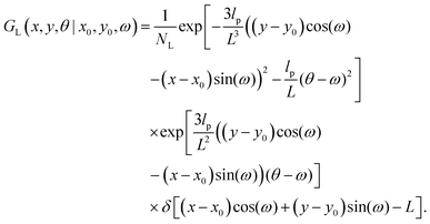 | (1) |
where NL is the normalization factor,  is the two dimensional persistence length, δ[x] is the Dirac delta function, kB is the Boltzmann constant and T is the temperature.
2.2 The grafted quadrilateral
Here, we study the elasticity of a grafted semiflexible quadrilateral. The quadrilateral is constructed by conjunction of four semiflexible filaments of length L. It has four corner labeled by 0, 11, 12, 21 according to Fig. 2. The conjunction angles are fixed since the length scales of the conjunction points are much smaller than the persistence length of the filaments. We put the origin of the coordinates at graft point of the system. The probability density to find the end corner of the quadrilateral labeled by 12 at position (x12,y12) and orientation θ12 is given by the following expression,| | 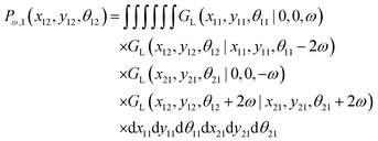 | (2) |
where ω > 0 is the grafting angle indicated in Fig. 2. We calculate integrals in eqn (2) and obtain the following analytic expression,| |  | (3) |
where| |  | (4) |
and| |  | (5) |
and| |  | (6) |
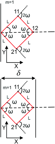 |
| | Fig. 1 The upper panel: The configuration of the grafted semiflexible quadrilateral at zero temperature. The lower panel: The grafted quadrilateral confined by a stiff planar wall. | |
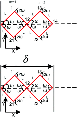 |
| | Fig. 2 The upper panel: The configuration of the grafted two longitudinally connected quadrilaterals at zero temperature. The lower panel: The two longitudinally connected quadrilaterals confined by a stiff planar wall. | |
We integrate the y component and angle θ in the probability density given by eqn (3) and obtain an expression for the probability density of finding the x component of position of the corner of quadrilateral labeled by 12 at value x,
| |  | (7) |
Similarly, we obtain the probability density of the position of the corner labeled by 12 at y coordinate,
| |  | (8) |
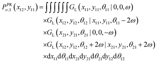
The probability density to find the x component of the position of the corner labeled by 12 at x12 and the y component of the position of the corner labeled by 11 at y11 is given by
| |  | (9) |
We obtain the analytic expression for the probability density after calculation of the integrals,
| |  | (10) |
where
| | 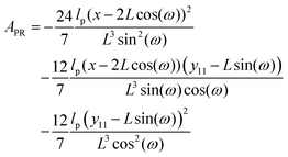 | (11) |
The probability densities in eqn (10), (7) and (8) give the associated force–extension relations. Using the similar method in ref. 88, we obtain the analytic expression for the x coordinate of the force–extension relation associated to the corner, 12 (see Appendix),
| |  | (12) |
where
H1 = 2
L![[thin space (1/6-em)]](https://www.rsc.org/images/entities/char_2009.gif)
cos(
ω) is the length of the system in the longitudinal direction at zero temperature. Similarly, the
y coordinate of the force–extension relation associated to the corner, 12 is given by the following expression (see Appendix),
| |  | (13) |
The equation, 〈fPRω,1(x,y11)〉 = 〈fXω,1(x)〉 results in the following equation
| |  | (14) |
which gives the relation between
y11 and
x (see Appendix),
| |  | (15) |
where
y11 −
L![[thin space (1/6-em)]](https://www.rsc.org/images/entities/char_2009.gif)
sin(
ω) is the displacement of the corner of the quadrilateral labeled by 11 in
y coordinate due to the displacement of the corner labeled by 12 in
x coordinate,
x − 2
L![[thin space (1/6-em)]](https://www.rsc.org/images/entities/char_2009.gif)
cos(
ω). The Poisson's ratio for the grafted semiflexible quadrilateral is (see Appendix)
| |  | (16) |
where
w = 2
L![[thin space (1/6-em)]](https://www.rsc.org/images/entities/char_2009.gif)
sin(
ω) is the width of the system at zero temperature. Next, we confine the system with a stiff wall in
x coordinate. The confining wall reduce the number of the configuration of the system and therefore experience a fluctuating force due to the confinement. The average of the fluctuating force on the confining stiff wall is (see Appendix)
| |  | (17) |
where
| |  | (18) |
2.3 Two longitudinally connected quadrilaterals grafted in a substrate
We connect another quadrilateral to the grafted quadrilateral according to the Fig. 2. The probability density to find the end point of the structure at position (x14,y14) with orientation θ14 is given by the following equation,| | 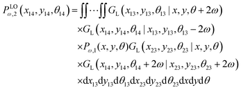 | (19) |
The probability density to find the position of the end point at x coordinate in value x is
| |  | (20) |
Similarly, we write the probability density to find the position of the end point at y coordinate in value y according to below,
| |  | (21) |
Using the probability density, we calculate the force–extension relation in x coordinate and it takes the following form (see Appendix),
| |  | (22) |
where the length of the system in longitudinal direction at zero temperature is
H2 = 4
L![[thin space (1/6-em)]](https://www.rsc.org/images/entities/char_2009.gif)
cos(
ω). Also, the force–extension relation in
y coordinate is (see Appendix)
| |  | (23) |
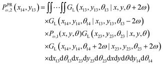
The probability density to find the x component of the position of the corner labeled by 14 at x14 and the y component of the position of the corner labeled by 13 at y13 is
| |  | (24) |
Similar to eqn (14) the equation in below
| |  | (25) |
gives relation between the lateral and the longitudinal displacement (see Appendix),
| |  | (26) |
where
y13 −
L![[thin space (1/6-em)]](https://www.rsc.org/images/entities/char_2009.gif)
sin(
ω) is the displacement of the corner of the quadrilateral labeled by 13 in
y coordinate due to the displacement of the corner labeled by 14 in
x coordinate,
x − 4
L![[thin space (1/6-em)]](https://www.rsc.org/images/entities/char_2009.gif)
cos(
ω). Therefore, the Poisson's ratio is
| |  | (27) |
Similar to the previous section, we confine the system by a stiff wall in x coordinate. The expression for the average of the fluctuating force on the confining stiff wall due to the confinement has the following form (see Appendix),
| |  | (28) |
where
| |  | (29) |
2.4
N number of the longitudinally connected quadrilaterals grafted in a substrate
Here, we study the elasticity of N number of the longitudinally connected quadrilaterals. The symmetry of the system implies that it is equivalent to a system consisting of N number of springs in series in a way that each spring has a Poisson's ratio of ν1 = cot2(ω)/2 which is equals to the Poisson's ratio of a grafted quadrilateral (see eqn (15)). Also, the force constant of each spring in x coordinate is equals to the force constant of a grafted quadrilateral in x coordinate, k = 6kBTlp/L3(sin(ω))2 (see eqn (12)). The force constant of N number of the springs in series is k/N (Fig. 3). Therefore, the force–extension relation of a system with the N number of the longitudinally connected quadrilaterals in x coordinate is| |  | (30) |
where the length of the system in x direction is HN = 2NL![[thin space (1/6-em)]](https://www.rsc.org/images/entities/char_2009.gif) cos(ω). The probability density of the x component of position of the tip of the polymeric system is
cos(ω). The probability density of the x component of position of the tip of the polymeric system is| |  | (31) |
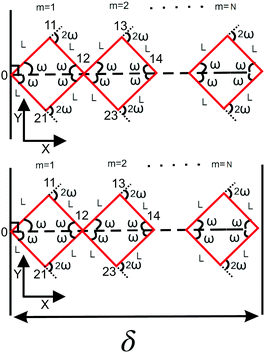 |
| | Fig. 3 The upper panel: The configuration of the grafted N number of the longitudinally connected quadrilaterals at zero temperature. The lower panel: The N number of the longitudinally connected quadrilaterals confined by a stiff planar wall. | |
Also, the Poisson's ratio of the system consisting of N number of springs is
| |  | (32) |
where Δ
x is the displacement of the tip of the system in the longitudinal direction and Δ
y is the contraction or the expansion of the system in the transverse direction.
Again, we confine the system with a stiff wall in x coordinate and calculate the average of the fluctuating force on the wall. The average of the exerted fluctuating force on the confining stiff wall by the fluctuating tip of the system is (see Appendix),
| |  | (33) |
where
| |  | (34) |
2.5 Comparison of the longitudinally connected quadrilaterals with different number of quadrilaterals having the same polymeric materials
Here, we vary the number of quadrilaterals in the system of longitudinally connected quadrilaterals while we keep the total contour length of the systems (the polymeric material of the system) the same. The force–extension relation of a system with the N number of the longitudinally connected quadrilaterals in x coordinate is (see eqn (30))| |  | (35) |
where LPM = 4NL is the total contour length of the system. The force constant associated with the force–extension relation is  . The dimensionless form of the force–extension relation is
| |  | (36) |
and the dimensionless force constant is  . If we keep the polymeric material of the system (LPM) fixed, the force constant will depend on the squared of the number of quadrilaterals. The higher the force constant, the stiffer the system. This fact shows that the system with higher number of quadrilateral with the same amount of polymeric material is stiffer as it can be seen from eqn (36).
It is interesting that the Poisson's ratio is independent of amount of the polymeric material used in the system (the total contour length) and only depends on the angle ω (see eqn (32))
| |  | (37) |
The average of the exerted fluctuating force on the confining stiff wall by the fluctuating tip of the system with the fixed total polymeric length, LPM is (see eqn (33))
| |  | (38) |
where
| |  | (39) |
The dimensionless form of the average of the force on the wall is
| |  | (40) |
Fig. 4 shows the average of the dimensionless force exerted to the wall by the system of the longitudinally connected quadrilaterals. We fix the polymeric material of the system and vary the number of the quadrilaterals for different curves. We look at the force–extension curves in two different regimes. In the first regime, δ < HN, the system is compressed by the wall therefore the mixture of the entropic forces and enthalpic forces play role in the elasticity of the system. In this regime, the force constant of the system increases as the number of quadrilaterals increases. In the second regime, δ > HN, the system is not compressed therefore the entropic forces play major role in the elasticity of the system. In this regime the system should be bent by the thermal fluctuations to hit the wall therefore the dimensionless force exerted to the wall decreases as the number of the quadrilaterals increases. In Fig. 5, we show the force–extension relation of the wall while we vary the value of the persistence length for the different curves. The force constant of the system increases in the regime, δ < HN, while the persistence length increases. We expected this fact since the system should be stiffer for higher values of the persistence length. In Fig. 6, we show the force–extension of the wall for different values of the angle, ω. The stiffness of the system increases as the value of the angle, ω decreases (Fig. 6).
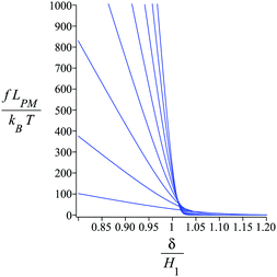 |
| | Fig. 4 The force–extension relation of the wall (the solutions of eqn (38)) is shown for different number of the quadrilaterals (N = 1, 2, 3, 4, 5, 6, 7, 8) while the polymeric material of the system is kept fixed. The higher the absolute value of the force constant (slope of the curve) in the range δ < HN the higher the number of the quadrilaterals. The fixed parameters are: kBT = 4.114 pN nm, lp = 50 nm, LPM = 30 nm,  and and  . . | |
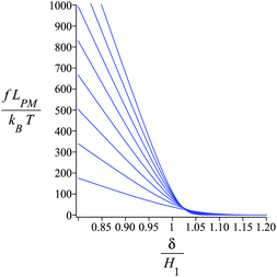 |
| | Fig. 5 The force–extension relation of the wall (the solutions of eqn (38)) is shown for different persistence length (lp = 10 nm, 20 nm, 30 nm, 40 nm, 50 nm, 60 nm, 70 nm, 80 nm) while the polymeric material of the system is kept fixed. The higher the absolute value of the force constant (slope of the curve) in the range δ < HN the higher the persistence length. The fixed parameters are: kBT = 4.114 pN nm, N = 3, LPM = 30 nm,  and and  . . | |
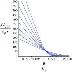 |
| | Fig. 6 The force–extension relation of the wall (the solutions of eqn (38)) is shown for different angles,  where i = 0, 1, 2, 3, 4, 5, 6, 7. The higher the absolute value of the force constant (slope of the curve) in the range δ < HN the lower the value of ω. The fixed parameters are: kBT = 4.114 pN nm, N = 3, lp = 50 nm, LPM = 30 nm, N = 3 and where i = 0, 1, 2, 3, 4, 5, 6, 7. The higher the absolute value of the force constant (slope of the curve) in the range δ < HN the lower the value of ω. The fixed parameters are: kBT = 4.114 pN nm, N = 3, lp = 50 nm, LPM = 30 nm, N = 3 and  . . | |
3 Discussion and conclusion
Here, we employed the worm-like chain model to describe the elastic behavior of a system made of longitudinally connected quadrilaterals. To obtain analytic expressions for the probability densities associated with the thermal fluctuation of the tip and the corners of the system, we used a positional–orientational propagator of a semiflexible filament in the weakly bending regime, which was introduced in ref. 6, 87 and 88. We used the probability densities to calculate the force–extension relation of the tip of the system for arbitrary number of the quadrilaterals in the fixed extension ensemble. We offered a closed analytic expression which is valid in the linear regime (since we used the weakly bending approximation). The force constant associated with the force–extension relation is proportional to the bending stiffness, κ and the squared of the number of the quadrilaterals, N2 and it is reversely proportional to the cubed of the total contour length (the amount of the polymeric material), LPM3 and sin2(ω). Also, we obtained an analytic expression for the Poisson's ratio of the system. It only depends on the angle, ω. The Poisson's ratio does not depend on the amount of polymeric material or the bending stiffness; therefore, it is a geometrical quantity of our system. In the last step, we confined the system with a planar stiff wall and calculated the average of the force exerted to the wall. The analytic expression for the average of the force depends on the persistence length, lp, total contour length, LPM, thermal energy, kBT, the number of the quadrilaterals, N, the angle, ω and the distance of the wall from the grafting point of the system, δ. All of the relations obtained in this article are closed analytic expressions therefore it is easy to theoretically track the behavior of the system in the parameter space of the linear force regime.
The theoretical model presented here can be applied to experimental and molecular modeling data available from research into DNA minicircles. Michele Caraglio et al. studied the DNA minicircles confined in a two dimensional space by a course grained model called the oxDNA.89 The oxDNA has two versions. The first version uses the symmetric grooves and is called the oxDNA1. The second version is implemented with asymmetric grooves. They reported rounded square shape for the case of the oxDNA1 and a circular shape for the case of oxDNA2 when the DNA minicircle is confined in a two dimensional space.89 Our calculations can be used to describe the two dimensional bending elasticity of the square shape of the DNA appeared in the model of oxDNA1. The bending modes of the DNA minicircles were studied by Davide Demurtas et al.90 A molecular dynamics study of minicircles was done by Marco Pasi et al.91 A theoretical study of the effect of bending anisotropy in minicircles is available in ref. 92. The circular shape of the DNA minicircles can be approximated with a square and then our model can be applied to describe the bending elasticity of them. The square shape structure made of the DNA is reported in ref. 93. Sungwook Woo et al. experimentally studied the self-assembly of two-dimensional DNA origami.94 They report a two dimensional square shape of DNA that can be arrange in one dimensional and two dimensional lattice. The elasticity of the one dimensional lattice made of squares of the DNA can be studied by our model (see Fig. 5 in ref. 94). The model presented in our article can be easily modified for describing the bending elasticity of semiflexible polymeric materials of more complex topologies which we suggest for future work.
Conflicts of interest
There are no conflicts to declare.
Appendix
A.1. The force–extension relation in the fixed-extension ensemble
Here, we consider a system made of a semiflexible polymer which is described by a Hamiltonian, H. We can look at the probability density function of the position of a fluctuating tip of a polymeric system in x coordinate as a partition function,88| |  | (41) |
where r(s) = (rx(s),ry(s),rz(t)) is the position vector associate with the arc length s and rx(L) is the position of the tip of the system in x coordinate. The partition function is in the fixed position ensemble because of the term, δ(rx(L) − x) which fixes the x component of the position of the tip in the value, x. The partition function gives the following term for the free energy associated with the tip,| | FX(x) = −kBT![[thin space (1/6-em)]](https://www.rsc.org/images/entities/char_2009.gif) ln(PX(x)) ln(PX(x)) | (42) |
The free energy defines the average of the x component of the force exerted to the tip in the fixed extension ensemble,
| |  | (43) |
This is the force–extension relation the fixed extension ensemble. The experimental setup for measuring the relation should be build in a way that the position of the tip in x coordinate is fixed while the other components of the position are free. In the experimental setup the force exerted in x coordinate would thermally fluctuate. By the similar reasoning we can obtain a force–extension relation in y coordinate,
| |  | (44) |
where
Py(
y) is the probability density function of the position of a fluctuating tip of a polymeric system in
y coordinate. In the next subsections, we will use
eqn (43) and (44) to calculate the force–extension relation associated with the connected quadrilaterals.
A.2. The Poisson's ratio
Here, we calculate the Poisson's ratio of a system. To do so, we consider the case of one grafted quadrilateral (see Fig. 2) and calculate the y component of displacement of the lateral point of the quadrilateral labeled by 11 in due to the displacement of the tip labeled by 12 in x coordinate. The probability density of the x component of the position if the tip of the quadrilateral (labeled by 12) is shown by PXω,1(x12). The force–extension relation associated with the probability density is| |  | (45) |
where 〈fx12(x12)〉 is the average of the fluctuating force in x coordinate that keeps the x component of extension of the tip labeled by 12 in the fixed value of x12 while the other points of the quadrilateral are free.
The probability density to find the x component of the position of the corner labeled by 12 at x12 and the y component of the position of the corner labeled by 11 at y11 is shown by PPRω,1(x12,y11). The force–extension relation associated with the probability density is given be the following equation,
| |  | (46) |
where 〈
fX12(
x12,
y11)〉 is the average of the fluctuating force in
x coordinate that keeps the
x component of position of the tip labeled by 12 in the fixed value of
x12 and the
y component of position of the point labeled by 11 in the fixed value of
y11 while the other points of the quadrilateral are free. The condition 〈
fPRω,1(
x12,
y11)〉 = 〈
fXω,1(
x12)〉 gives the relation between
y11 and the fixed value of
x12. Inserting
eqn (45) and (46) in the condition, we find the relation between the lateral contraction or the lateral expansion of the system due to the longitudinal displacement of the end point of the system
| |  | (47) |
We define the Poisson's ratio of the quadrilateral as follows,
| |  | (48) |
A.3. The force exerted to a stiff confining wall by a fluctuating tip
Here, we take the grafted quadrilateral as an example of the polymeric system and confine the system by a stiff and impenetrable wall in x coordinate. The distance of the wall from the grafting point of the quadrilateral is fixed, δ while the fluctuating tip of the quadrilateral exerts a fluctuating force on the wall. We are interested in calculating the average of the force (see Fig. 1, 2 and 7). To do so, we use the method introduced in ref. 6 and 95. The origin of the force comes from the reduction of the number of the configuration of the system due to the presence of the wall. The number of the configuration of the system is given by the following equation6,95| |  | (49) |
where PXω,1(x12) is the probability density to find the x component of the position of the tip of the quadrilateral at the value, x12. The derivative of the logarithm of the number of the configuration of the system with respect to δ is the average of the fluctuating force| |  | (50) |
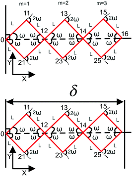 |
| | Fig. 7 The upper panel: The configuration of the grafted three longitudinally connected quadrilaterals at zero temperature. The lower panel: The three longitudinally connected quadrilaterals confined by a stiff planar wall. | |
In this method, we ignore the steric effect of the wall and the other corners of the system.
A.4. Three longitudinally connected quadrilaterals grafted in a substrate
The probability density to find the end point of the grafted three longitudinally connected quadrilateral in position (x16,y16) and orientation, θ16 is| | 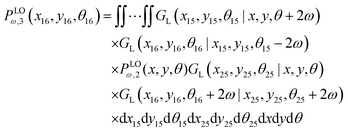 | (51) |
We obtain the probability density to find the position of the end point of the structure in x coordinate at value x according to below,
| |  | (52) |
Similarly, the probability density to find the position of the end point of the structure in y coordinate at value y is of the following form,
| |  | (53) |
The force–extension relation in x coordinate result from the probability density function according to below (see Appendix),
| |  | (54) |
where
H3 = 6
L![[thin space (1/6-em)]](https://www.rsc.org/images/entities/char_2009.gif)
cos(
ω). Similarly, we obtain the force–extension relation in
y coordinate (see Appendix),
| |  | (55) |
To calculate the Poisson's ratio, we have to calculate the following quantity (see Appendix),
| | 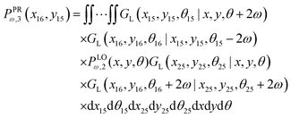 | (56) |
which is the probability density to find the
x component of the position of the corner labeled by 16 at the value of
x16 and the
y component of the position of the point labeled by 15 at the value of
y15. The relation between the displacement in lateral direction and the displacement in longitudinal direction is given by the following equation,
| |  | (57) |
which is of the following form
| |  | (58) |
where
y115 −
L![[thin space (1/6-em)]](https://www.rsc.org/images/entities/char_2009.gif)
sin(
ω) is the displacement of the corner of the quadrilateral labeled by 15 in
y coordinate due to the displacement of the corner labeled by 16 in
x coordinate,
x − 6
L![[thin space (1/6-em)]](https://www.rsc.org/images/entities/char_2009.gif)
cos(
ω). Therefore the Poisson's ratio is
| |  | (59) |
As with the previous section, if we confine the system by a stiff wall in x coordinate the wall will experience a fluctuating force. The average of the fluctuating force on the confining stiff wall is (see Appendix)
| |  | (60) |
where
| |  | (61) |
Acknowledgements
M. R. acknowledges the support by Iran National Science Foundation (INSF), and A. M. acknowledges the support by Muscular Dystrophy Association (USA), Grant Number MDA628071.
Notes and references
- D. A. Fletcher and R. D. Mullins, Nature, 2010, 463, 485–492 CrossRef CAS
 .
.
- A. Chaigne, C. Campillo, R. Voituriez, N. S. Gov, C. Sykes, M.-H. Verlhac and M.-E. Terret, Nat. Commun., 2016, 7, 1–14 Search PubMed
 .
.
- R. Zhang, N. Kumar, J. L. Ross, M. L. Gardel and J. J. De Pablo, Proc. Natl. Acad. Sci. U. S. A., 2018, 115, E124–E133 CrossRef CAS
 .
.
- P. A. Janmey, S. Hvidt, J. Käs, D. Lerche, A. Maggs, E. Sackmann, M. Schliwa and T. P. Stossel, J. Biol. Chem., 1994, 269, 32503–32513 CAS
 .
.
- L. Blanchoin, R. Boujemaa-Paterski, C. Sykes and J. Plastino, Physiol. Rev., 2014, 94, 235–263 CrossRef CAS
 .
.
- M. Razbin, M. Falcke, P. Benetatos and A. Zippelius, Phys. Biol., 2015, 12, 046007 CrossRef
 .
.
- D. E. Dupuis, W. H. Guilford, J. Wu and D. Warshaw, J. Muscle Res. Cell Motil., 1997, 18, 17–30 CrossRef CAS
 .
.
- F. Rückerl, M. Lenz, T. Betz, J. Manzi, J.-L. Martiel, M. Safouane, R. Paterski-Boujemaa, L. Blanchoin and C. Sykes, Biophys. J., 2017, 113, 1072–1079 CrossRef
 .
.
- S. Walcott and S. X. Sun, Proc. Natl. Acad. Sci. U. S. A., 2010, 107, 7757–7762 CrossRef CAS
 .
.
- K. Kasza, C. Broedersz, G. Koenderink, Y. Lin, W. Messner, E. Millman, F. Nakamura, T. Stossel, F. MacKintosh and D. Weitz, Biophys. J., 2010, 99, 1091–1100 CrossRef CAS
 .
.
- M. Gardel, J. H. Shin, F. MacKintosh, L. Mahadevan, P. Matsudaira and D. Weitz, Science, 2004, 304, 1301–1305 CrossRef CAS
 .
.
- M. Guo, A. J. Ehrlicher, S. Mahammad, H. Fabich, M. H. Jensen, J. R. Moore, J. J. Fredberg, R. D. Goldman and D. A. Weitz, Biophys. J., 2013, 105, 1562–1568 CrossRef CAS
 .
.
- N. Wang and D. Stamenovic, J. Muscle Res. Cell Motil., 2002, 23, 535–540 CrossRef
 .
.
- P. Pawelzyk, N. Mücke, H. Herrmann and N. Willenbacher, PLoS One, 2014, 9, e93194 CrossRef
 .
.
- W. H. Goldmann, Cell Biol. Int., 2018, 42, 132–138 CrossRef CAS
 .
.
- L. Kreplak and D. Fudge, BioEssays, 2007, 29, 26–35 CrossRef CAS
 .
.
- D. S. Fudge, K. H. Gardner, V. T. Forsyth, C. Riekel and J. M. Gosline, Biophys. J., 2003, 85, 2015–2027 CrossRef CAS
 .
.
- S. Köster, D. A. Weitz, R. D. Goldman, U. Aebi and H. Herrmann, Curr. Opin. Cell Biol., 2015, 32, 82–91 CrossRef
 .
.
- G. J. Brouhard and L. M. Rice, Nat. Rev. Mol. Cell Biol., 2018, 19, 451–463 CrossRef CAS
 .
.
- S. Forth and T. M. Kapoor, J. Cell Biol., 2017, 216, 1525–1531 CrossRef CAS
 .
.
- T. Li, J. Biomech., 2008, 41, 1722–1729 CrossRef
 .
.
- D. K. Fygenson, J. F. Marko and A. Libchaber, Phys. Rev. Lett., 1997, 79, 4497 CrossRef CAS
 .
.
- T. Hawkins, M. Mirigian, M. S. Yasar and J. L. Ross, J. Biomech., 2010, 43, 23–30 CrossRef
 .
.
- D. Havelka, M. A. Deriu, M. Cifra and O. Kučera, Sci. Rep., 2017, 7, 1–11 CrossRef CAS
 .
.
- J. Howard and A. A. Hyman, Nature, 2003, 422, 753–758 CrossRef CAS
 .
.
- T. R. Strick, J.-F. Allemand, D. Bensimon, A. Bensimon and V. Croquette, Science, 1996, 271, 1835–1837 CrossRef CAS
 .
.
- M. Rief, H. Clausen-Schaumann and H. E. Gaub, Nat. Struct. Biol., 1999, 6, 346–349 CrossRef CAS
 .
.
- C. Bustamante, Z. Bryant and S. B. Smith, Nature, 2003, 421, 423–427 CrossRef
 .
.
- C. Bustamante, S. B. Smith, J. Liphardt and D. Smith, Curr. Opin. Struct. Biol., 2000, 10, 279–285 CrossRef CAS
 .
.
- J. F. Marko and E. D. Siggia, Macromolecules, 1995, 28, 8759–8770 CrossRef CAS
 .
.
- A. Ahsan, J. Rudnick and R. Bruinsma, Biophys. J., 1998, 74, 132–137 CrossRef CAS
 .
.
- C. Bouchiat and M. Mezard, Phys. Rev. Lett., 1998, 80, 1556 CrossRef CAS
 .
.
- J. F. Marko and E. D. Siggia, Macromolecules, 1994, 27, 981–988 CrossRef CAS
 .
.
- M. D. Wang, H. Yin, R. Landick, J. Gelles and S. M. Block, Biophys. J., 1997, 72, 1335 CrossRef CAS
 .
.
- M. Heidari, H. Schiessel and A. Mashaghi, ACS Cent. Sci., 2020, 6(6), 839–847, DOI:10.1021/acscentsci.0c00308
 .
.
- B. Scalvini, V. Sheikhhassani, J. Woodard, J. Aupič, R. T. Dame, R. Jerala and A. Mashaghi, Trends Chem., 2020, 2(7), 609–622, DOI:https://doi.org/10.1016/j.trechm.2020.04.009
 .
.
- C. A. Mirkin, R. L. Letsinger, R. C. Mucic and J. J. Storhoff, Nature, 1996, 382, 607–609 CrossRef CAS
 .
.
- C. M. Niemeyer, W. Bürger and J. Peplies, Angew. Chem., Int. Ed., 1998, 37, 2265–2268 CrossRef CAS
 .
.
- K. Keren, M. Krueger, R. Gilad, G. Ben-Yoseph, U. Sivan and E. Braun, Science, 2002, 297, 72–75 CrossRef CAS
 .
.
- W. E. Ford, O. Harnack, A. Yasuda and J. M. Wessels, Adv. Mater., 2001, 13, 1793–1797 CrossRef CAS
 .
.
- A. P. Alivisatos, K. P. Johnsson, X. Peng, T. E. Wilson, C. J. Loweth, M. P. Bruchez and P. G. Schultz, Nature, 1996, 382, 609–611 CrossRef CAS
 .
.
- D. Nykypanchuk, M. M. Maye, D. Van Der Lelie and O. Gang, Nature, 2008, 451, 549–552 CrossRef CAS
 .
.
- Y. Zhang, F. Lu, K. G. Yager, D. Van Der Lelie and O. Gang, Nat. Nanotechnol., 2013, 8, 865–872 CrossRef CAS
 .
.
- A. R. Chandrasekaran and O. Levchenko, Chem. Mater., 2016, 28, 5569–5581 CrossRef CAS
 .
.
- C. E. Castro, F. Kilchherr, D.-N. Kim, E. L. Shiao, T. Wauer, P. Wortmann, M. Bathe and H. Dietz, Nat. Methods, 2011, 8, 221 CrossRef CAS
 .
.
- P. W. Rothemund, Nature, 2006, 440, 297–302 CrossRef CAS
 .
.
- L. Qian, Y. Wang, Z. Zhang, J. Zhao, D. Pan, Y. Zhang, Q. Liu, C. Fan, J. Hu and L. He, Chin. Sci. Bull., 2006, 51, 2973–2976 CrossRef CAS
 .
.
- S. M. Douglas, J. J. Chou and W. M. Shih, Proc. Natl. Acad. Sci. U. S. A., 2007, 104, 6644–6648 CrossRef CAS
 .
.
- E. S. Andersen, M. Dong, M. M. Nielsen, K. Jahn, A. Lind-Thomsen, W. Mamdouh, K. V. Gothelf, F. Besenbacher and J. Kjems, ACS Nano, 2008, 2, 1213–1218 CrossRef CAS
 .
.
- Y. Ke, J. Sharma, M. Liu, K. Jahn, Y. Liu and H. Yan, Nano Lett., 2009, 9, 2445–2447 CrossRef CAS
 .
.
- E. S. Andersen, M. Dong, M. M. Nielsen, K. Jahn, R. Subramani, W. Mamdouh, M. M. Golas, B. Sander, H. Stark and C. L. Oliveira,
et al.
, Nature, 2009, 459, 73–76 CrossRef CAS
 .
.
- E. Pound, J. R. Ashton, H. A. Becerril and A. T. Woolley, Nano Lett., 2009, 9, 4302–4305 CrossRef CAS
 .
.
- D. Han, S. Pal, Y. Liu and H. Yan, Nat. Nanotechnol., 2010, 5, 712–717 CrossRef CAS
 .
.
- W. Liu, H. Zhong, R. Wang and N. C. Seeman, Angew. Chem., Int. Ed., 2011, 50, 264–267 CrossRef CAS
 .
.
- B. Saccà, R. Meyer, M. Erkelenz, K. Kiko, A. Arndt, H. Schroeder, K. S. Rabe and C. M. Niemeyer, Angew. Chem., 2010, 122, 9568–9573 CrossRef
 .
.
-
N. C. Seeman, Structural DNA nanotechnology, Cambridge University Press, 2015 Search PubMed
 .
.
- K. Lund, A. J. Manzo, N. Dabby, N. Michelotti, A. Johnson-Buck, J. Nangreave, S. Taylor, R. Pei, M. N. Stojanovic and N. G. Walter,
et al.
, Nature, 2010, 465, 206–210 CrossRef CAS
 .
.
- E. Winfree, F. Liu, L. A. Wenzler and N. C. Seeman, Nature, 1998, 394, 539–544 CrossRef CAS
 .
.
- S. M. Douglas, H. Dietz, T. Liedl, B. Högberg, F. Graf and W. M. Shih, Nature, 2009, 459, 414–418 CrossRef CAS
 .
.
- H. Dietz, S. M. Douglas and W. M. Shih, Science, 2009, 325, 725–730 CrossRef CAS
 .
.
- D. Han, S. Pal, J. Nangreave, Z. Deng, Y. Liu and H. Yan, Science, 2011, 332, 342–346 CrossRef CAS
 .
.
- K. E. Dunn, F. Dannenberg, T. E. Ouldridge, M. Kwiatkowska, A. J. Turberfield and J. Bath, Nature, 2015, 525, 82–86 CrossRef CAS
 .
.
- F. Zhang, S. Jiang, S. Wu, Y. Li, C. Mao, Y. Liu and H. Yan, Nat. Nanotechnol., 2015, 10, 779 CrossRef CAS
 .
.
- E. Benson, A. Mohammed, J. Gardell, S. Masich, E. Czeizler, P. Orponen and B. Högberg, Nature, 2015, 523, 441–444 CrossRef CAS
 .
.
- R. Veneziano, S. Ratanalert, K. Zhang, F. Zhang, H. Yan, W. Chiu and M. Bathe, Science, 2016, 352, 1534 CrossRef CAS
 .
.
- J. Song, Z. Li, P. Wang, T. Meyer, C. Mao and Y. Ke, Science, 2017, 357(6349) DOI:10.1126/science.aan3377
 .
.
- E. Kopperger, J. List, S. Madhira, F. Rothfischer, D. C. Lamb and F. C. Simmel, Science, 2018, 359, 296–301 CrossRef CAS
 .
.
- H. Jun, F. Zhang, T. Shepherd, S. Ratanalert, X. Qi, H. Yan and M. Bathe, Sci. Adv., 2019, 5, eaav0655 CrossRef
 .
.
-
N. C. Seeman, DNA Nanotechnology, Springer, 2018, pp. 1–9 Search PubMed
 .
.
- H.-P. Hsu, W. Paul and K. Binder, EPL, 2010, 92, 28003 CrossRef
 .
.
- J. Z. Chen, Prog. Polym. Sci., 2016, 54, 3–46 CrossRef
 .
.
- M. Razbin, P. Benetatos and A. Zippelius, Phys. Rev. E, 2016, 93, 052408 CrossRef
 .
.
- R. G. Winkler, J. Chem. Phys., 2003, 118, 2919–2928 CrossRef CAS
 .
.
- L. Livadaru, R. Netz and H. Kreuzer, Macromolecules, 2003, 36, 3732–3744 CrossRef CAS
 .
.
- C. Heussinger, M. Bathe and E. Frey, Phys. Rev. Lett., 2007, 99, 048101 CrossRef
 .
.
- J. Wilhelm and E. Frey, Phys. Rev. Lett., 1996, 77, 2581 CrossRef CAS
 .
.
- R. Vlijm, A. Mashaghi, S. Bernard, M. Modesti and C. Dekker, Nanoscale, 2015, 7, 3205–3216 RSC
 .
.
- S. Bezrukavnikov, A. Mashaghi, R. J. van Wijk, C. Gu, L. J. Yang, Y. Q. Gao and S. J. Tans, Soft Matter, 2014, 10, 7269–7277 RSC
 .
.
- K. C. Neuman and A. Nagy, Nat. Methods, 2008, 5, 491–505 CrossRef CAS
 .
.
- T. Strick, M. Dessinges, G. Charvin, N. Dekker, J. Allemand, D. Bensimon and V. Croquette, Rep. Prog. Phys., 2002, 66, 1 CrossRef
 .
.
- J. R. Moffitt, Y. R. Chemla, S. B. Smith and C. Bustamante, Annu. Rev. Biochem., 2008, 77(1), 205–228, DOI:10.1146/annurev.biochem.77.043007.090225
 .
.
- S. B. Smith, L. Finzi and C. Bustamante, Science, 1992, 258, 1122–1126 CrossRef CAS
 .
.
- K. Kim and O. A. Saleh, Nucleic Acids Res., 2009, 37, e136 CrossRef
 .
.
- M. Rief, F. Oesterhelt, B. Heymann and H. E. Gaub, Science, 1997, 275, 1295–1297 CrossRef CAS
 .
.
- T. T. Perkins, D. Smith and S. Chu,
et al.
, Science, 1994, 264, 822–826 CrossRef CAS
 .
.
- S. Dutta and P. Benetatos, Soft Matter, 2018, 14, 6857–6866 RSC
 .
.
- P. Benetatos and E. Frey, Phys. Rev. E: Stat., Nonlinear, Soft Matter Phys., 2003, 67, 051108 CrossRef CAS
 .
.
- M. Razbin, J. Stat. Phys., 2018, 170, 642–651 CrossRef
 .
.
- M. Caraglio, E. Skoruppa and E. Carlon, J. Chem. Phys., 2019, 150, 135101 CrossRef
 .
.
- D. Demurtas, A. Amzallag, E. J. Rawdon, J. H. Maddocks, J. Dubochet and A. Stasiak, Nucleic Acids Res., 2009, 37, 2882–2893 CrossRef CAS
 .
.
- M. Pasi, K. Zakrzewska, J. H. Maddocks and R. Lavery, Nucleic Acids Res., 2017, 45, 4269–4277 CrossRef CAS
 .
.
- D. Norouzi, F. Mohammad-Rafiee and R. Golestanian, Phys. Rev. Lett., 2008, 101, 168103 CrossRef
 .
.
- D. Han, S. Jiang, A. Samanta, Y. Liu and H. Yan, Angew. Chem., 2013, 125, 9201–9204 CrossRef
 .
.
- S. Woo and P. W. Rothemund, Nat. Commun., 2014, 5, 1–11 Search PubMed
 .
.
- A. Gholami, J. Wilhelm and E. Frey, Phys. Rev. E: Stat., Nonlinear, Soft Matter Phys., 2006, 74, 041803 CrossRef
 .
.
|
| This journal is © The Royal Society of Chemistry 2021 |
Click here to see how this site uses Cookies. View our privacy policy here.  Open Access Article
 *a and
Alireza
Mashaghi
 *b
*b
 where κ is the bending stiffness of the filament and t(s) is the tangent vector of the filament in the arc length s. Here, we study the filament confined in a two dimensional space. In the weakly bending regime, the density probability of finding the end point of such filament at position, (x,y) with orientation, θ given the grafted tip at position, (x0,y0) with orientation, ω is as follows,6,87,88
 is the two dimensional persistence length, δ[x] is the Dirac delta function, kB is the Boltzmann constant and T is the temperature.


![[thin space (1/6-em)]](https://www.rsc.org/images/entities/char_2009.gif) cos(ω) is the length of the system in the longitudinal direction at zero temperature. Similarly, the y coordinate of the force–extension relation associated to the corner, 12 is given by the following expression (see Appendix),
cos(ω) is the length of the system in the longitudinal direction at zero temperature. Similarly, the y coordinate of the force–extension relation associated to the corner, 12 is given by the following expression (see Appendix),


![[thin space (1/6-em)]](https://www.rsc.org/images/entities/char_2009.gif) sin(ω) is the displacement of the corner of the quadrilateral labeled by 11 in y coordinate due to the displacement of the corner labeled by 12 in x coordinate, x − 2L
sin(ω) is the displacement of the corner of the quadrilateral labeled by 11 in y coordinate due to the displacement of the corner labeled by 12 in x coordinate, x − 2L![[thin space (1/6-em)]](https://www.rsc.org/images/entities/char_2009.gif) cos(ω). The Poisson's ratio for the grafted semiflexible quadrilateral is (see Appendix)
cos(ω). The Poisson's ratio for the grafted semiflexible quadrilateral is (see Appendix)
![[thin space (1/6-em)]](https://www.rsc.org/images/entities/char_2009.gif) sin(ω) is the width of the system at zero temperature. Next, we confine the system with a stiff wall in x coordinate. The confining wall reduce the number of the configuration of the system and therefore experience a fluctuating force due to the confinement. The average of the fluctuating force on the confining stiff wall is (see Appendix)
sin(ω) is the width of the system at zero temperature. Next, we confine the system with a stiff wall in x coordinate. The confining wall reduce the number of the configuration of the system and therefore experience a fluctuating force due to the confinement. The average of the fluctuating force on the confining stiff wall is (see Appendix)


![[thin space (1/6-em)]](https://www.rsc.org/images/entities/char_2009.gif) cos(ω). Also, the force–extension relation in y coordinate is (see Appendix)
cos(ω). Also, the force–extension relation in y coordinate is (see Appendix)


![[thin space (1/6-em)]](https://www.rsc.org/images/entities/char_2009.gif) sin(ω) is the displacement of the corner of the quadrilateral labeled by 13 in y coordinate due to the displacement of the corner labeled by 14 in x coordinate, x − 4L
sin(ω) is the displacement of the corner of the quadrilateral labeled by 13 in y coordinate due to the displacement of the corner labeled by 14 in x coordinate, x − 4L![[thin space (1/6-em)]](https://www.rsc.org/images/entities/char_2009.gif) cos(ω). Therefore, the Poisson's ratio is
cos(ω). Therefore, the Poisson's ratio is


![[thin space (1/6-em)]](https://www.rsc.org/images/entities/char_2009.gif) cos(ω). The probability density of the x component of position of the tip of the polymeric system is
cos(ω). The probability density of the x component of position of the tip of the polymeric system is


 . The dimensionless form of the force–extension relation is
 . If we keep the polymeric material of the system (LPM) fixed, the force constant will depend on the squared of the number of quadrilaterals. The higher the force constant, the stiffer the system. This fact shows that the system with higher number of quadrilateral with the same amount of polymeric material is stiffer as it can be seen from eqn (36).


 and
and  .
.
 and
and  .
.
 where i = 0, 1, 2, 3, 4, 5, 6, 7. The higher the absolute value of the force constant (slope of the curve) in the range δ < HN the lower the value of ω. The fixed parameters are: kBT = 4.114 pN nm, N = 3, lp = 50 nm, LPM = 30 nm, N = 3 and
  .
.
![[thin space (1/6-em)]](https://www.rsc.org/images/entities/char_2009.gif) ln(PX(x))
ln(PX(x))


![[thin space (1/6-em)]](https://www.rsc.org/images/entities/char_2009.gif) cos(ω). Similarly, we obtain the force–extension relation in y coordinate (see Appendix),
cos(ω). Similarly, we obtain the force–extension relation in y coordinate (see Appendix),


![[thin space (1/6-em)]](https://www.rsc.org/images/entities/char_2009.gif) sin(ω) is the displacement of the corner of the quadrilateral labeled by 15 in y coordinate due to the displacement of the corner labeled by 16 in x coordinate, x − 6L
sin(ω) is the displacement of the corner of the quadrilateral labeled by 15 in y coordinate due to the displacement of the corner labeled by 16 in x coordinate, x − 6L![[thin space (1/6-em)]](https://www.rsc.org/images/entities/char_2009.gif) cos(ω). Therefore the Poisson's ratio is
cos(ω). Therefore the Poisson's ratio is


.
.
.
.
.
.
.
.
.
.
.
.
.
.
.
.
.
.
.
.
.
.
.
.
.
.
.
.
.
.
.
.
.
.
.
.
.
.
.
.
.
.
.
.
.
.
.
.
.
.
.
.
.
.
.
.
.
.
.
.
.
.
.
.
.
.
.
.
.
.
.
.
.
.
.
.
.
.
.
.
.
.
.
.
.
.
.
.
.
.
.
.
.
.
.


