
 Open Access Article
 This Open Access Article is licensed under a
 Creative Commons Attribution 3.0 Unported Licence
Heterostructures of ε-Fe2O3 and α-Fe2O3: insights from density functional theory
Imran Ahamed a,
Nicola Serianib,
Ralph Gebauerb and
Arti Kashyap*c
a,
Nicola Serianib,
Ralph Gebauerb and
Arti Kashyap*c
aSchool of Basic Sciences, Indian Institute of Technology, Mandi, Himachal Pradesh 175005, India
bThe Abdus Salam International Centre for Theoretical Physics (ICTP), Strada Costiera 11, 34151 Trieste, Italy
cSchool of Basic Sciences, School of Computing and Electrical Engineering, Indian Institute of Technology, Mandi, Himachal Pradesh 175005, India. E-mail: arti@iitmandi.ac.in
First published on 22nd July 2020
Abstract
Many materials used in energy devices or applications suffer from the problem of electron–hole pair recombination. One promising way to overcome this problem is the use of heterostructures in place of a single material. If an electric dipole forms at the interface, such a structure can lead to a more efficient electron–hole pair separation and thus prevent recombination. Here we model and study a heterostructure comprised of two polymorphs of Fe2O3. Each one of the two polymorphs, α-Fe2O3 and ε-Fe2O3, individually shows promise for applications in photoelectrochemical cells. The heterostructure of these two materials is modeled by means of density functional theory. We consider both ferromagnetic as well as anti-ferromagnetic couplings at the interface between the two systems. Both individual oxides are insulating in nature and have an anti-ferromagnetic spin arrangement in their ground state. The same properties are found also in their heterostructure. The highest occupied electronic orbitals of the combined system are localized at the interface between the two iron-oxides. The localization of charges at the interface is characterized by electrons residing close to the oxygen atoms of ε-Fe2O3 and electron–holes localized on the iron atoms of α-Fe2O3, just around the interface. The band alignment at the interface of the two oxides shows a type-III broken band-gap heterostructure. The band edges of α-Fe2O3 are higher in energy than those of ε-Fe2O3. This band alignment favours a spontaneous transfer of excited photo-electrons from the conduction band of α- to the conduction band of ε-Fe2O3. Similarly, photo-generated holes are transferred from the valence band of ε- to the valence band of α-Fe2O3. Thus, the interface favours a spontaneous separation of electrons and holes in space. The conduction band of ε-Fe2O3, lying close to the valence band of α-Fe2O3, can result in band-to-band tunneling of electrons which is a characteristic property of such type-III broken band-gap heterostructures and has potential applications in tunnel field-effect transistors.
Introduction
At the interface between two different materials one can often observe new emergent physical properties and phenomena which are not found in the individual materials.1,2 For example, LaAlO3 and SrTiO3 both are insulating materials, but in a heterostructure, the interface of these systems was found to be metallic.3 In general, oxides can have properties ranging from ferroelectric to piezoelectric, bandgap insulating or superconducting, etc. Such properties are related to the lattice structure and the symmetry of the materials. By forming heterostructures of these oxides, the crystal lattice is disturbed and the symmetries are broken, which alters the properties of the combined system. Using various techniques, heterostructures of oxides can be prepared with novel properties, such as the presence of two dimensional electron gas (2DEG) at the interface of LaAlO3/SrTiO3 (ref. 3) and also in KNbO3/BaTiO3, KNbO3/PbTiO3, KNbO3/SrTiO3 heterointerfaces.4 Very high electron mobilities ∼ 106 cm2 V−1 s−1 were observed at the heterointerface of MgZnO/ZnO.5 The interface of LaAlO3/SrTiO3 was also found to be superconductive.6,7 Very recently, a high-mobility spin-polarized 2DEG was observed at the interface of EuO/KTaO3.8 Emergent giant topological Hall effect is also observed in heterostructures of LaSrMnO3/SrIrO3.9Heterostructures can also be important for electron–hole separation in photoactive devices. Here we are interested in iron oxides that have demonstrated potential as photocatalysts, but suffer from high recombination. Bulk ε-Fe2O3 is an indirect band-gap semiconducting material with a gap of 1.9 eV,10,11 whereas bulk α-Fe2O3 is a direct band-gap semiconducting material with 2.2 eV of band-gap.12,13 Bulk ε-Fe2O3 is magnetically hard with a room temperature coercivity of 20 kOe,14–16 while bulk α-Fe2O3 is magnetically very soft with a room temperature coercivity of a few 100 Oe.17–19 Single crystals of ε-Fe2O3 are not naturally found nor prepared experimentally, but it is always obtained in mixtures with α-Fe2O3 and its other polymorphs. Also, both ε- and α-Fe2O3 being charge-transfer insulators,10,20 the heterostructures of these two polymorphs can show exciting phenomena at the interface, just like various other transition metals oxide heterostructures.
Both these phases of iron-oxide have been theoretically studied and also experimentally proven for H2 production from sunlight in photoelectrochemical (PEC) cells with different production rates.21–28 The application of ε- and α-Fe2O3 in energy devices such as PEC cells suffers from the presence of surface states acting as trap sites for electron–holes which also favour the recombination of photo-generated electron–hole pairs.27,29 To increase the efficiency of the PEC cells with α-Fe2O3 photoelectrodes, the surface states can be passivated by growing overlayers of Al2O3, Ga2O3 or In2O3.30–32 The efficiency of ε-Fe2O3 is found much higher in H2 production in PEC cells in comparison with α-Fe2O3.28 Like in the case of BiFeO3,33,34 the magnetoelectric/ferroelectric nature of ε-Fe2O3 (ref. 35) reduces the recombination of photo-generated charges thus giving higher H2 yield in comparison with α-Fe2O3 used in PEC cells.
Heterostructures are proven to show a great amount of reduction of electron–hole recombination by separating the two charges.36–38 The energy band alignment of the two materials at the interface of the heterostructure of BiFeO3/ε-Fe2O3 is such that it facilitates the separation of electron–hole pairs.39 Very recently, epitaxial thin films of α-Fe2O3 was grown on multiferroic ε-Fe2O3 supported on SrTiO3 as a substrate for a possible application as a 4-resistive state multiferroic tunnel junction (MFTJ).40 Since then, heterojunctions of semiconductors, insulators or semiconductor–insulator junctions show unique electronic and magnetic properties. For this reason, we have explored the heterostructure of two semiconducting oxides, namely the two different polymorphs of Fe2O3.
Here, we have investigated the heterostructures of Fe2O3 by first-principles calculations. We modelled the heterointerface of ε-Fe2O3 and α-Fe2O3, the two polymorphs of Fe2O3. The interface formation energy of the heterointerface is calculated for the various magnetic couplings, yielding the stable magnetic ordering in the heterostructure. The electronic structure of the heterostructure of the anti-ferromagnetic α-Fe2O3 and multiferroic ε-Fe2O3 is calculated and the interface states are determined. We have obtained the charge transfer in the ε/α-Fe2O3 system by means of the charge density difference and also from the band alignment. We have shown the band alignment at the interface of ε-Fe2O3 and α-Fe2O3 subsystems forming the heterostructure by taking a common vacuum level as reference for the combined system as well as for the individual subsystems. In this way, the band offset and the direction of the charge flow across the interface is determined.
Calculation details
We have performed spin-polarized density functional theory (DFT) calculations as implemented in VASP (Vienna Ab initio Simulation Package).41–43 The Perdew–Burke–Ernzerhoff (PBE)44 form of the generalized gradient approximation was used for the treatment of the exchange–correlation effects. We have used the projected augmented wave (PAW)45 method and pseudo-potentials with d7s1 and s2p4 as the valence configurations for Fe- and O-atoms, respectively. The DFT+U formalism46,47 was used to account for the strongly correlated nature of the localized electrons. An effective Hubbard-U parameter48 is introduced. This U-correction is applied to the Fe 3d-states, and its value is chosen to be 4 eV. This value is commonly used for hematite.20 U − J = 4 eV is reported to give a band gap in close agreement with the ab initio study for bulk ε-Fe2O3 (ref. 10 and 11) and also for bulk α-Fe2O3.20 The U value chosen for the Fe-atoms are same for the surface and bulk atoms as opposed to the work of Lewandowski et al.49 because the Fe-atoms at the interface has the same environment above and below it. Structural optimizations of each slab of Fe2O3 and of their heterostructure and calculation of the density of states of the heterostructure were carried out using a Monkhorst–Pack (M–P)50 k-point mesh of 5 × 3 × 1 points in the Brillouin zone. To represent the electronic wave orbitals, we have used a plane-wave basis set with an energy cutoff of 530 eV. The atoms of the heterostructure were selectively relaxed in the z-direction only in a constant volume cell using a conjugate gradient optimization51 algorithm. The convergence criteria for electronic self-consistency was set to 10−7 eV and for the forces in relaxations to 0.005 eV Å−1 for each atom. Due to the non-centrosymmetric nature of bulk ε-Fe2O3 and also the heterostructures of ε/α-Fe2O3, the two surfaces are not same and thus are not dipole neutral. In order to apply a dipole correction, compensating dipoles52,53 are introduced in the vacuum region of the slab of each iron oxide and also for their heterostructure.Modelling of heterostructure
ε-Fe2O3 has an orthorhombic structure with space group Pna21. The DFT-optimized lattice parameters were found to be a = 5.125 Å, b = 8.854 Å and c = 9.563 Å which are in good agreement with the experimental lattice parameters.27 The bulk unit cell contains eight formula units of Fe2O3 having four inequivalent Fe sites. The four inequivalent (FeA, FeB, FeC, FeD) type atoms have the following respective spins: β, α, α, β, which gives an A-type anti-ferromagnetic coupling as shown in Fig. 1(a) α-Fe2O3 has a corundum structure and there are six formula units of Fe2O3 in its unit cell. The structure of hematite is rhombohedrally centered hexagonal with space group R![[3 with combining macron]](https://www.rsc.org/images/entities/char_0033_0304.gif) c having DFT optimized lattice parameters as a = 5.038 Å and c = 13.772 Å which are in close agreement with the experimental lattice parameter.54,55 It consists of hexagonal closed pack arrays of oxygen stacked along the [001] direction. Hematite has an anti-ferromagnetic spin arrangement as shown in Fig. 1(b) and has net zero magnetization.
c having DFT optimized lattice parameters as a = 5.038 Å and c = 13.772 Å which are in close agreement with the experimental lattice parameter.54,55 It consists of hexagonal closed pack arrays of oxygen stacked along the [001] direction. Hematite has an anti-ferromagnetic spin arrangement as shown in Fig. 1(b) and has net zero magnetization.
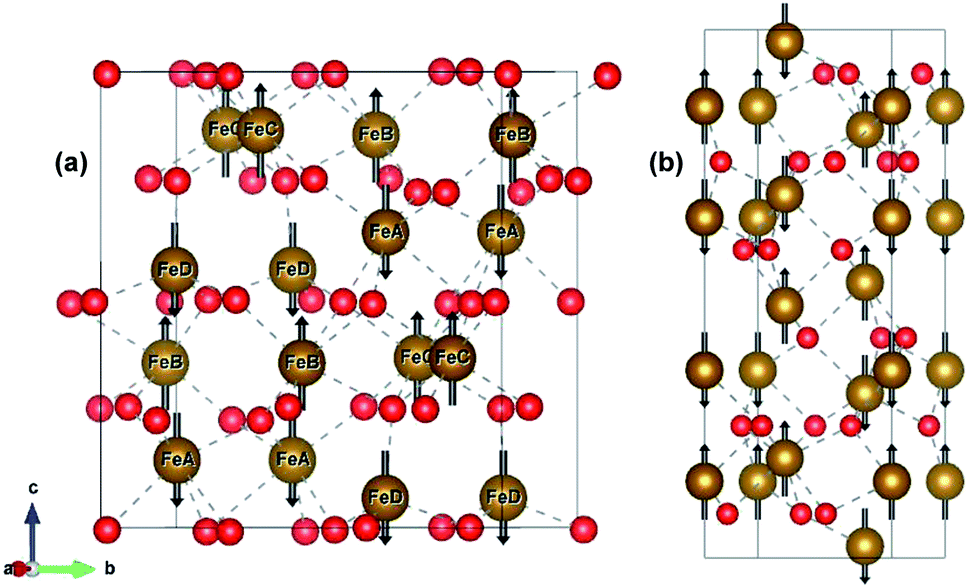 | ||
| Fig. 1 Bulk structure of (a) ε-Fe2O3 and (b) α-Fe2O3. Bonds are shown in broken grey lines. The arrows represents the direction of the magnetic moment of the Fe-atoms. Red and brown atoms represents the O- and Fe-atoms, respectively. | ||
Since the unit cell of α-Fe2O3 and ε-Fe2O3 is hexagonal and orthorhombic, respectively, the lattice mismatch is huge and the modelling of the interface is difficult. For the interface modelling, we have taken one unit cell thick slab of ε-Fe2O3 having 8 formula units of Fe2O3 and an orthorhombic slab of α-Fe2O3 having one oxygen atom less than 11 formula units of Fe2O3 modelled from its hexagonal super cell as shown in Fig. 2.
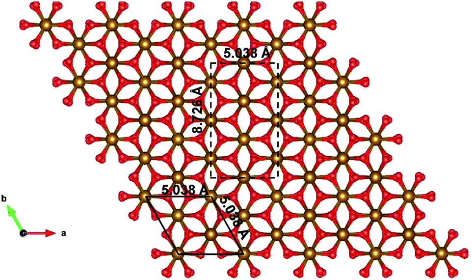 | ||
| Fig. 2 Modelled orthorhombic structure of α-Fe2O3 from the supercell of hexagonal unit cell of α-Fe2O3. Bulk unit cell is in black solid line and the modelled orthorhombic cell is in black broken line. | ||
The preferred growth direction of the slabs of ε-Fe2O3 and α-Fe2O3 is along the [001] direction.40,50–61 The slabs are prepared from optimized bulk structures by the supercell approach in the crystallographic c-axis with a vacuum of 15 Å and the ions were allowed to relax. The lattice mismatch between the orthorhombic ε-Fe2O3 and the modelled orthorhombic α-Fe2O3 is 1.69% and 1.44% along the x- and y-directions, respectively. The slab of ε-Fe2O3 and α-Fe2O3 have the same thickness as that of its bulk unit cell, i.e., of 9.563 Å and 13.772 Å, respectively. The layers of α-Fe2O3 consist of Fe-atoms in octahedral coordination with oxygen, so the only choice would be to have an oxygen or an iron terminated surface. However, this cancels out with the choice of the termination in the other phase, because the interface must respect the alternation of iron and oxygen layers in order to be stable. For ε-Fe2O3, the layers consist of Fe-atoms in octahedral, tetrahedral, and a mix of octahedral and tetrahedral coordination with oxygen atoms. In order to make a perfect interface with the α-Fe2O3 so that we have an interface of low defect and low trap density, we have chosen the ε-Fe2O3 slab with a top surface as an octahedral coordination. Any other choice would greatly increase the number of interface atoms with non-optimal coordination. The optimized orthorhombic slabs of both iron-oxides for the heterostructure modelling are shown in Fig. 3.
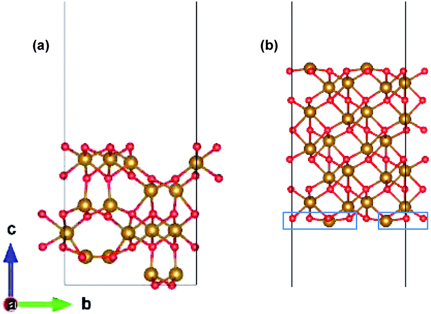 | ||
| Fig. 3 Optimized slab of (a) ε-Fe2O3 and (b) α-Fe2O3 for the preparation of the heterostructure. | ||
The heterostructure is modelled by placing the slab of α-Fe2O3 on top of ε-Fe2O3 with a separation of 2 Å and allowed to selectively relax in the z-direction of the heterostructure with 15 Å vacuum provided along z-direction. Since both these phases of Fe2O3 have layered anti-ferromagnetic spin arrangement, therefore the interface could be prepared with ferromagnetic or anti-ferromagnetic coupling between ε- and α-Fe2O3 at the interface. The interface heterostructure of ε/α-Fe2O3 is obtained by removing the two Fe-atoms and four O-atoms (marked in blue rectangle) from the bottom of the slab of α-Fe2O3 and combining it with the ε-Fe2O3 slab. The 2 × FeO2 units are removed from the bottom surface of α-Fe2O3 in order to make a perfectly coordinated interface consisting of only octahedrally coordinated Fe-atoms.
Results and discussion
Interface stability
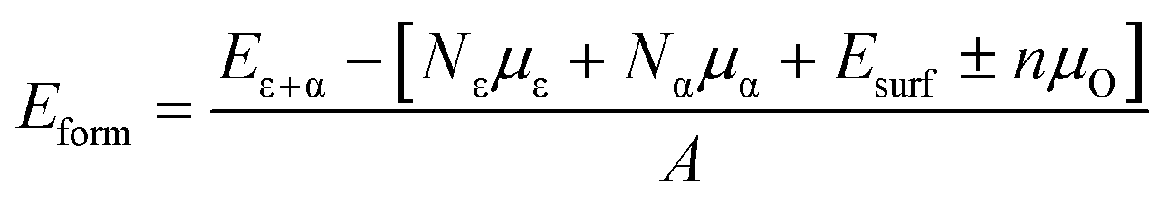
The stability of the modelled heterostructure is checked by calculating the interface formation energy of the heterostructure having different magnetic couplings at the interface. The interface formation energy (Eform)62 is expressed as
 | (1) |
The surface energy (Esurf) used in eqn (1) is obtained from the sum of two separate calculations for both the bottom and top surface made due to the slabs of ε-Fe2O3 and α-Fe2O3, respectively, by using the equation25,27 as
 | (2) |
For all energies in eqn (1) and (2) we employ the DFT total energies, neglecting entropic effects, which however will not affect the relative stability of the interface.62
The interface energy calculated for the heterostructure with ferromagnetic and anti-ferromagnetic coupling at the interface between the two slabs is 0.099 and 0.086 eV Å−2, respectively. Comparing the two numbers we find that the magnetic coupling at the interface is slightly preferred to be anti-ferromagnetic. The calculated interface energy is positive, but very small, which is indicating that the formation of a heterostructure is energetically not hindered.
Electronic properties and interface states
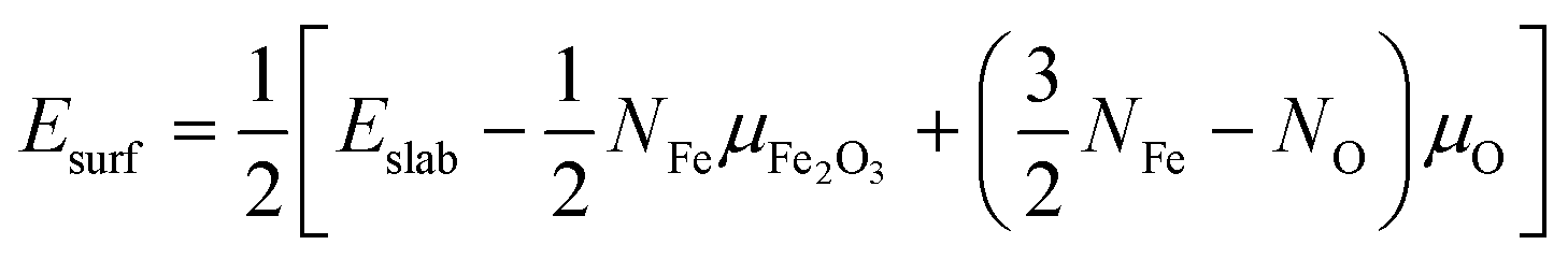
The electronic structure is shown in layer wise manner along with the heterostructure in Fig. 4. The heterostructure is divided into layers such that each partial density of states (PDOS) correspond to each layer consisting of two formula units of Fe2O3 except for the first-bottom and the tenth-top PDOS. The first-bottom PDOS consists of two formula units of Fe2O2 and the top tenth-layer PDOS consists of Fe2O6.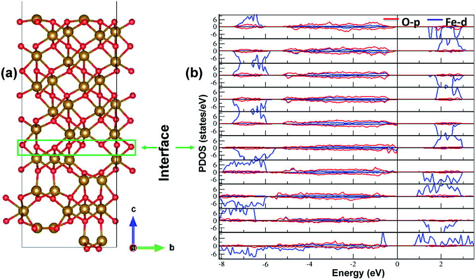 | ||
| Fig. 4 The interface of ε-Fe2O3 and α-Fe2O3 along with the partial density of states (PDOS) of the heterostructure in a layer-wise manner. Red and blue curve in the PDOS represents the density of O-p and Fe-d orbitals, respectively. | ||
The interface formed (marked as a green rectangle in Fig. 4(a)) between the two slabs of Fe2O3 polymorphs is made up of O-atoms of ε-Fe2O3. As it is seen from the partial density of states (PDOS) in Fig. 4(b), each layer of the heterostructure is an insulator and no conducting state appears at the interface. A sharp peak below the Fermi level in the first bottom layer of PDOS corresponds to a surface state due to the d-orbitals of Fe-atoms. In the interface layer, fifth from the bottom, there are states appearing just below the Fermi level which are otherwise not present in any of the layers. These states correspond to the highest occupied molecular orbital (HOMO) and are mainly contributed from the O-atoms in the interface. This is also evident from the partial charge density corresponding to the HOMO as shown in Fig. 5. The Fe-atoms in the interface layer of the DOS just above the O-atoms also contribute, but very weakly, in the HOMO.
 | ||
| Fig. 5 The interface of ε-Fe2O3 and α-Fe2O3 showing the orbitals contributing to the highest occupied states at the interface. | ||
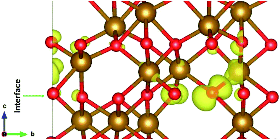
Charge-density difference
The charge distribution in the heterostructure due to the formation of interface is analysed by taking the charge density difference of the heterostructure and each part of Fe2O3 slabs. The charge density difference is calculated by the use of following equation:| Δρ = ρε/α − ρε − ρα | (3) |
 | ||
| Fig. 6 The charge density difference of ε/α-Fe2O3 interface heterostructure. The yellow region shows the charge accumulation and the cyan region shows charge depletion. The isosurface value is ±0.005 e Å−3. | ||
The charge density difference shows that the charge is redistributed mainly at the interface of ε- and α-Fe2O3. The maximum charge accumulation is at the interface, on the O-atoms which belong to ε-Fe2O3 and also very small on Fe-atoms above the interface. The Fe-atoms above the interface belonging to α-Fe2O3 have more charge depletion. The Fe-atoms below the interface belonging to the ε-Fe2O3 side have very little or no charge accumulations. This charge redistribution suggests that the electron is transferred from α-Fe2O3 to the ε-Fe2O3 slab and the holes remains on the bottom Fe-atoms of the α-Fe2O3 slab. The localization of charges on the atoms at the interface does not contributes to any conducting states, making the heterostructure act like an insulator. The transfer of charges form one material to the other leads to net charge accumulation and thus creates a built-in electric field at the interface. This electric field can contribute to a more efficient separation of electrons and holes in the heterostructure, thus suppressing charge recombination.63
Electrostatic potential and the band offsets
The nature of the electronic energy levels plays an important role for the use of materials in energy applications. The formation of a heterostructure interface of two semiconductors requires that their vacuum levels align at the interface. This is known as Anderson's electron affinity rule.64,65 The band positions with respect to the vacuum energy levels were obtained from our DFT calculations on the optimized slabs of ε-Fe2O3 and α-Fe2O3 separately. Since the separate slabs of ε- and α-Fe2O3 are not dipole neutral, a dipole correction was applied for obtaining the correct value of vacuum potential. With the correct value of the vacuum potential, the average electrostatic potential (ESP) of the slab of ε-Fe2O3, α-Fe2O3 and their complete heterostructures with a common reference vacuum level is plotted and shown in Fig. 7.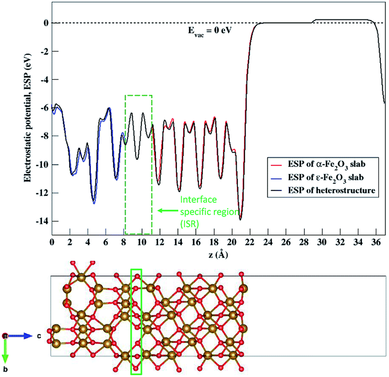 | ||
| Fig. 7 Average electrostatic potential (ESP) of the separate slabs of ε-Fe2O3 (blue curve), α-Fe2O3 (red curve) and their complete heterostructure (black curve). The broken line represents the vacuum potential. The rectangle in green broken lines represents the interface specific region (ISR). | ||
The ESP of the heterostructure matches well with the ESP of the individual separate slabs of ε- and α-Fe2O3. The O-atoms of ε-Fe2O3 slabs contributes in interface formation, so they are counted as the interface and lie in the interface specific region (ISR). The position of the valence band and conduction band with respect to the vacuum energy level was calculated for both the separate iron-oxide slabs and plotted as shown in Fig. 8. The conduction band CB, valence band VB, electron affinity χ and band gap Eg are shown for both the slabs in Fig. 8. The subscript ε and α in the band gap and electron affinity represents that these quantities are associated with the slab of ε- and α-Fe2O3, respectively.
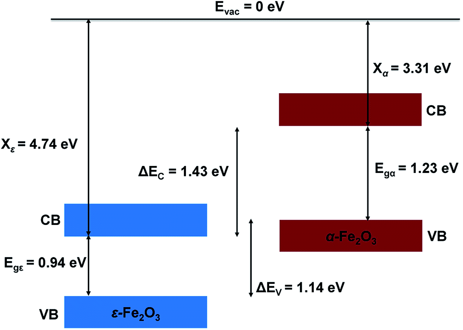 | ||
| Fig. 8 Schematic diagram showing the band alignment of ε-Fe2O3 and α-Fe2O3 slabs before connection. | ||
From Fig. 8 it is clear that the valence band edge of α-Fe2O3 is higher than the conduction band edge of ε-Fe2O3. Both band edges of α-Fe2O3 are higher than that of ε-Fe2O3 and this arrangement of band edges falls in the category of type-III broken-gap heterostructures.66 Since the band edges of α-Fe2O3 lies above the band edges of ε-Fe2O3, the work function of α-Fe2O3 will be lower than that of the ε-Fe2O3. Before the formation of the interface in the heterojunction, the band of each slab system is unaffected by each other. As soon as the junction is formed and the charges flow spontaneously across it and reach equilibrium, a band bending occurs at the interface. This flow of charges takes place across the interface and a built in voltage is developed across it. The direction of the electric field across the interface will be from ε- to the α-Fe2O3 as shown in Fig. 9.
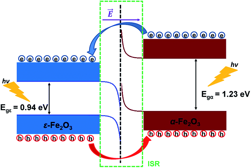 | ||
| Fig. 9 Schematic diagram showing the band bending and the charge flow at the interface of ε-Fe2O3 and α-Fe2O3 heterostructure after connection. | ||
The band bending at the interface of the heterostructure is shown in Fig. 9. When the photons are incident on the heterostructure, the generation of electron–hole pairs takes place and the electron jumps to the CBs in both the Fe2O3 slabs leaving the holes in the VBs of the respective Fe2O3 material. Due to the nature of the alignment of the bands and the difference in their respective conduction band edges, which is the conduction band offset (CBO), the electrons flow from the CB of α-Fe2O3 to the CB of ε-Fe2O3. Similarly, the holes flow from the VB of ε-Fe2O3 to the VB of α-Fe2O3. This type-III of band alignment at the interface results in the separation of photogenerated charges. The electron prefers to reside in ε-Fe2O3 and the hole prefers α-Fe2O3.
Since the valence band maximum (VBM) of the α-Fe2O3 slab is higher than the conduction band minimum (CBM) of ε-Fe2O3, the electron can tunnel from the VBM of α-Fe2O3 to the CBM of ε-Fe2O3. This band-to-band tunneling (BTBT) in type-III heterostructure results in negative differential resistance (NDR) and can be used in tunnel field-effect transistors (TEFT).67–70
Conclusion
In summary, we have modelled the heterostructure of the two readily available polymorphs of Fe2O3. Both ε-Fe2O3 and α-Fe2O3 are charge-transfer insulators and their heterostructure also remains an insulator. The interface energy explains the anti-ferromagnetic spin arrangement at the interface which results in overall reduced magnetization. There is a localization of charges at the interface which occurs because of the strain at the interface between the two slabs of Fe2O3. The charge density difference also suggests that electrons are localized at the interface on oxygen atoms of ε-Fe2O3 and holes above the interface on iron atoms of α-Fe2O3. The band alignment with respect to a reference vacuum potential at zero eV, gives a rare type-III heterostructure. The band bending at the interface shows the transfer of electrons from α-Fe2O3 to the ε-Fe2O3 and the holes from ε-Fe2O3 to α-Fe2O3. The heterostructure showing charge separation at the interface reduces the recombination rate of the photo-generated electron–hole pairs and can thus give better efficiency in comparison to the use of a single material as photoelectrode in PEC cells. The broken band type-III heterostructure can show band-to-band tunneling and find applications in field-effect transistors.Conflicts of interest
There are no conflicts of interest to declare.Acknowledgements
This work is supported by Nano Mission, DST, India (SR/NM/NS-1198/2013, IA, AK). AK acknowledges Simons Associate, ICTP, Italy and IA acknowledges ICTP, Italy.References
- H. Y. Hwang, Y. Iwasa, M. Kawasaki, B. Keimer, N. Nagaosa and Y. Tokura, Nat. Mater., 2012, 11, 103 CrossRef CAS PubMed.
- J. W. Reiner, F. J. Walker and C. H. Ahn, Science, 2009, 323, 1018 CrossRef CAS PubMed.
- A. Ohtomo and H. Y. Hwang, Nature, 2004, 427, 423 CrossRef CAS PubMed.
- Y. Wang, M. K. Niranjan, S. S. Jaswal and E. Y. Tsymbal, Phys. Rev. B: Condens. Matter Mater. Phys., 2009, 80, 165130 CrossRef.
- J. Falson, Y. Kozuka, M. Uchida, J. H. Smet, T. Arima, A. Tsukazaki and M. Kawasaki, Sci. Rep., 2016, 6, 26598 CrossRef CAS PubMed.
- J. A. Bert, B. Kalisky, C. Bell, M. Kim, Y. Hikita, H. Y. Hwang and K. A. Moler, Nat. Phys., 2011, 7, 767 Search PubMed.
- A. Kalaboukhov, P. P. Aurino, L. Galletti, T. Bauch, F. Lombardi, D. Winkler, T. Claeson and D. Golubev, Phys. Rev. B, 2017, 96, 184525 CrossRef.
- H. Zhang, Y. Yun, X. Zhang, H. Zhang, Y. Ma, X. Yan, F. Wang, G. Li, R. Li, T. Khan, Y. Chen, W. Liu, F. Hu, B. Liu, B. Shen, W. Han and J. Sun, Phys. Rev. Lett., 2018, 121, 116803 CrossRef CAS PubMed.
- Y. Li, L. Zhang, Q. Zhang, C. Li, T. Yang, Y. Deng, L. Gu and D. Wu, ACS Appl. Mater. Interfaces, 2019, 11, 21268 CrossRef CAS PubMed.
- M. Yoshikiyo, K. Yamada, A. Namai and S. Ohkoshi, J. Phys. Chem. C, 2012, 116, 8688 CrossRef CAS.
- I. Ahamed, R. Pathak, R. Skomski and A. Kashyap, AIP Adv., 2018, 8, 055815 CrossRef.
- N. Beermann, L. Vayssieres, S. Lindquist and A. Hagfeldt, J. Electrochem. Soc., 2000, 147, 2456 CrossRef CAS.
- A. Kleiman-Shwarsctein, Y. Hu, A. J. Forman, G. D. Stucky and E. W. McFarland, J. Phys. Chem. C, 2008, 112, 15900 CrossRef CAS.
- R. Zboril, M. Mashlan and D. Petridis, Chem. Mater., 2002, 14, 969 CrossRef CAS.
- M. Popovici, M. Gich, D. Nižňanský, A. Roig, C. Savii, L. Casas, E. Molins, K. Zaveta, C. Enache, J. Sort, S. de Brion, G. Chouteau and J. Nogués, Chem. Mater., 2004, 16, 5542 CrossRef CAS.
- J. Jin, S. Ohkoshi and K. Hashimoto, Adv. Mater., 2004, 16, 48 CrossRef CAS.
- A. P. Roberts, Y. Cui and K. L. Verosub, J. Geophys. Res.: Solid Earth, 1995, 100, 17909 CrossRef.
- O. Özdemir and D. J. Dunlop, J. Geophys. Res.: Solid Earth, 2014, 119, 2582 CrossRef.
- M. Ahmadzadeh, J. Marcial and J. McCloy, J. Geophys. Res.: Solid Earth, 2017, 122, 2504 CrossRef CAS.
- G. Rollmann, A. Rohrbach, P. Entel and J. Hafner, Phys. Rev. B: Condens. Matter Mater. Phys., 2004, 69, 165107 CrossRef.
- J. H. Kennedy and K. W. Frese, J. Electrochem. Soc., 1978, 125, 709 CrossRef CAS.
- M. P. Dare-Edwards, J. B. Goodenough, A. Hamnett and P. R. Trevellick, J. Chem. Soc., Faraday Trans. 1, 1983, 79, 2027 RSC.
- P. Liao, J. A. Keith and E. A. Carter, J. Am. Chem. Soc., 2012, 134, 13296 CrossRef CAS PubMed.
- M. J. Katz, S. C. Riha, N. C. Jeong, A. B. Martinson, O. K. Farha and J. T. Hupp, Coord. Chem. Rev., 2012, 256, 2521 CrossRef CAS.
- M.-T. Nguyen, N. Seriani and R. Gebauer, J. Chem. Phys., 2013, 138, 194709 CrossRef PubMed.
- M. H. Dahan and M. Caspary Toroker, J. Phys. Chem. C, 2017, 121, 6120 CrossRef CAS.
- I. Ahamed, K. Ulman, N. Seriani, R. Gebauer and A. Kashyap, J. Chem. Phys., 2018, 148, 214707 CrossRef PubMed.
- G. Carraro, C. Maccato, A. Gasparotto, T. Montini, S. Turner, O. I. Lebedev, V. Gombac, G. Adami, G. Van Tendeloo, D. Barreca and P. Fornasiero, Adv. Funct. Mater., 2014, 24, 372 CrossRef CAS.
- N. Ansari, K. Ulman, M. F. Camellone, N. Seriani, R. Gebauer and S. Piccinin, Phys. Rev. Mater., 2017, 1, 035404 CrossRef.
- F. Le Formal, N. Tétreault, M. Cornuz, T. Moehl, M. Grätzel and K. Sivula, Chem. Sci., 2011, 2, 737 RSC.
- T. Hisatomi, F. Le Formal, M. Cornuz, J. Brillet, N. Tétreault, K. Sivula and M. Grätzel, Energy Environ. Sci., 2011, 4, 2512 RSC.
- K. Ulman, M.-T. Nguyen, N. Seriani and R. Gebauer, J. Chem. Phys., 2016, 144, 094701 CrossRef PubMed.
- W. Ji, K. Yao, Y.-F. Lim, Y. C. Liang and A. Suwardi, Appl. Phys. Lett., 2013, 103, 062901 CrossRef.
- D. Cao, Z. Wang, W. L. Nasori, Y. Mi and Y. Lei, Angew. Chem., 2014, 126, 11207 CrossRef.
- M. Gich, C. Frontera, A. Roig, J. Fontcuberta, E. Molins, N. Bellido, C. Simon and C. Fleta, Nanotechnology, 2006, 17, 687 CrossRef CAS.
- Z. Zhang and J. T. Yates, Chem. Rev., 2012, 112, 5520 CrossRef CAS PubMed.
- L. Li, P. A. Salvador and G. S. Rohrer, Nanoscale, 2014, 6, 24 RSC.
- W. Yang, Y. Yu, M. B. Starr, X. Yin, Z. Li, A. Kvit, S. Wang, P. Zhao and X. Wang, Nano Lett., 2015, 15, 7574 CrossRef CAS PubMed.
- L. T. Quynh, C. N. Van, Y. Bitla, J.-W. Chen, T. H. Do, W.-Y. Tzeng, S.-C. Liao, K.-A. Tsai, Y.-C. Chen, C.-L. Wu, C.-H. Lai, C.-W. Luo, Y.-J. Hsu and Y.-H. Chu, Adv. Energy Mater., 2016, 6, 1600686 CrossRef.
- M. Watanabe, Determinations in Nanomedicine and Nanotechnology, 2019, 1, 000502 Search PubMed.
- G. Kresse and J. Furthmüller, Comput. Mater. Sci., 1996, 6, 15 CrossRef CAS.
- G. Kresse and J. Furthmüller, Phys. Rev. B: Condens. Matter Mater. Phys., 1996, 54, 11169 CrossRef CAS PubMed.
- G. Kresse and D. Joubert, Phys. Rev. B: Condens. Matter Mater. Phys., 1999, 59, 1758 CrossRef CAS.
- J. P. Perdew, K. Burke and M. Ernzerhof, Phys. Rev. Lett., 1997, 78, 1396 CrossRef CAS.
- P. E. Blöchl, Phys. Rev. B: Condens. Matter Mater. Phys., 1994, 50, 17953 CrossRef PubMed.
- V. I. Anisimov, J. Zaanen and O. K. Andersen, Phys. Rev. B: Condens. Matter Mater. Phys., 1991, 44, 943 CrossRef CAS PubMed.
- M. Cococcioni and S. de Gironcoli, Phys. Rev. B: Condens. Matter Mater. Phys., 2005, 71, 035105 CrossRef.
- J. Hubbard, Proc. R. Soc. London, Ser. A, 1963, 276, 238 Search PubMed.
- M. Lewandowski, I. M. N. Groot, Z.-H. Qin, T. Ossowski, T. Pabisiak, A. Kiejna, A. Pavlovska, S. Shaikhutdinov, H.-J. Freund and E. Bauer, Chem. Mater., 2016, 28, 7433 CrossRef CAS.
- H. J. Monkhorst and J. D. Pack, Phys. Rev. B: Solid State, 1976, 13, 5188 CrossRef.
- M. R. Hestenes and E. Stiefel, J. Res. Natl. Bur. Stand., 1952, 49, 409 CrossRef.
- J. Neugebauer and M. Scheffler, Phys. Rev. B: Condens. Matter Mater. Phys., 1992, 46, 16067 CrossRef CAS PubMed.
- G. Makov and M. C. Payne, Phys. Rev. B: Condens. Matter Mater. Phys., 1995, 51, 4014 CrossRef CAS PubMed.
- L. Pauling and S. B. Hendricks, J. Am. Chem. Soc., 1925, 47, 781 CrossRef CAS.
- L. W. Finger and R. M. Hazen, J. Appl. Phys., 1980, 51, 5362 CrossRef CAS.
- M. Gich, J. Gazquez, A. Roig, A. Crespi, J. Fontcuberta, J. C. Idrobo, S. J. Pennycook, M. Varela, V. Skumryev and M. Varela, Appl. Phys. Lett., 2010, 96, 112508 CrossRef.
- L. Corbellini, C. Lacroix, C. Harnagea, A. Korinek, G. A. Botton, D. Ménard and A. Pignolet, Sci. Rep., 2017, 7, 3712 CrossRef.
- A. Tanskanen, O. Mustonen and M. Karppinen, APL Mater., 2017, 5, 056104 CrossRef.
- A. Rohrbach, J. Hafner and G. Kresse, Phys. Rev. B: Condens. Matter Mater. Phys., 2004, 70, 125426 CrossRef.
- W. Bergermayer, H. Schweiger and E. Wimmer, Phys. Rev. B: Condens. Matter Mater. Phys., 2004, 69, 195409 CrossRef.
- C. M. Eggleston, Am. Mineral., 1999, 84, 1061 CrossRef CAS.
- Y. F. Dong, Y. P. Feng, S. J. Wang and A. C. H. Huan, Phys. Rev. B: Condens. Matter Mater. Phys., 2005, 72, 045327 CrossRef.
- J. Liu, J. Phys. Chem. C, 2015, 119, 28417 CrossRef CAS.
- R. L. Anderson, IBM J. Res. Dev., 1960, 4, 283 CAS.
- R. Anderson, Solid-State Electron., 1962, 5, 341 CrossRef CAS.
- J. Zhang, M. Zhang, R.-Q. Sun and X. Wang, Angew. Chem., Int. Ed., 2012, 51, 10145 CrossRef CAS PubMed.
- R. Yan, S. Fathipour, Y. Han, B. Song, S. Xiao, M. Li, N. Ma, V. Protasenko, D. A. Muller, D. Jena and H. G. Xing, Nano Lett., 2015, 15, 5791 CrossRef CAS PubMed.
- J. Shim, S. Oh, D.-H. Kang, S.-H. Jo, M. H. Ali, W.-Y. Choi, K. Heo, J. Jeon, S. Lee, M. Kim, Y. J. Song and J.-H. Park, Nat. Commun., 2016, 7, 13413 CrossRef CAS PubMed.
- C. Xia, J. Du, M. Li, X. Li, X. Zhao, T. Wang and J. Li, Phys. Rev. Appl., 2018, 10, 054064 CrossRef CAS.
- C. Lei, Y. Ma, X. Xu, T. Zhang, B. Huang and Y. Dai, J. Phys. Chem. C, 2019, 123, 23089 CrossRef CAS.
| This journal is © The Royal Society of Chemistry 2020 |