DOI:
10.1039/D0RA04912C
(Paper)
RSC Adv., 2020,
10, 27456-27473
The dielectric relaxation behavior induced by sodium migration in the Na2CoSiO4 structure within a three-dimensional Co–O–Si framework
Received
4th June 2020
, Accepted 14th July 2020
First published on 22nd July 2020
Abstract
The disodium cobalt(II) orthosilicate material (NCS) has been synthesized using improved solid-state (NCS-SS) and co-precipitation (NCS-CP) methods of synthesis. The Rietveld refinement of the XRD pattern of Na2CoSiO4 has demonstrated an orthorhombic crystal system with the space groups Pna21 and Pbca for NCS-SS and NCS-CP respectively. The elemental mapping of microstructures by scanning electron microscopy-energy dispersive spectroscopy (SEM-EDS) showed the porous morphology and the homogenous particles of the Na2CoSiO4 powders. Their dielectric properties were measured in the frequency and temperature ranges of 0.1–106 Hz and 383–613 K respectively. Different dielectric relaxation phenomena associated with the Na+-ion migration through different paths were displayed in relation with the temperature and frequency. The decrease and increase in the dielectric properties were found to be dependent on the formation of short-range ordered structure formed after the migration of Na+-ions. In the present work, an attempt has been made to study the relation between the structural properties and the dielectric process. Thus, interesting insights into the transport behavior of Na+-ions in different chemical environments were obtained. This in turn provides an effective procedure to probe the relationship between the diffusion pathway of Na+-ions and the dielectric response.
1. Introduction
Recently, considerable attention has been paid to Na-ion batteries (NIBs) with high energy density, low price and toxicity, relatively low self-discharge, good chemical stability, good mechanical stability and dielectric properties.1–5 Additionally, sodium is located below lithium in the periodic table, thus, such physical and chemical properties as ionic charge, electronegativity and electrochemical reactivity are very similar,6–8 which makes NIBs an attractive alternative to lithium-ion batteries (LIBs). More importantly, there are large numbers of resources of Na and Si in the Earth's crust. Na2CoSiO4 exhibits significantly lower polarization than Na2FeSiO4 and Na2MnSiO4. Much like Li2CoSiO4, sodium cobalt-based orthosilicate (Na2CoSiO4) tends to be a good choice to serve as the cathode material in NIBs.9 WU Shun-qing et al.10 proved that changing the amount of Na in Li2CoSiO4 has a great influence on the structural properties. More precisely, this change is due to the presence of sodium and the distortion of its local environment, especially the SiO4 and CoO4 tetrahedra. Accordingly, we can notice that the sodium-ion migration and its environment are responsible for the physical proprieties which are significant for the cathode materials.11,12 The polymorphism of the cristobalite is porous while the arrangement of the transition metal silicate brings about large tunneling sites that can incorporate the diffusion of the cations.13,14 Disodium cobalt orthosilicate has attractive properties such as a high structural stability, a high Na+ diffusion of 8.0 × 10⁻¹² cm2 s−1 at 300 K (ref. 15) and a good electrical conductivity which is reported to be purely ionic.16 The Na+ diffusion indicates a very low activation barrier and a 3D network of diffusion pathways through the SiO4 and MO4 frameworks,17 which both suggest favorable Na+ intercalation kinetics.
The dielectric permittivity, the dielectric loss and the electric modulus must be carried out in order to demonstrate the migration of sodium-ion in broad temperature and frequency ranges as well as to obtain a better understanding of the relaxation mechanism. Nevertheless, only few researchers have studied the dielectric properties of electrodes.
Finding a relationship between the composition, the structure and the dielectric properties should be of considerable interest. Therefore, the aim of this work is (a) to reexamine the structure of Na2CoSiO4 by the improved solid-state and co-precipitation methods, (b) to discuss its crystal chemical characteristics and its microstructure morphologies, and (c) to investigate the relaxation behavior of the Na+-ion migration as a function of the temperature, the frequency and the synthesis methods.
2. Experimental
2.1. Synthesis of Na2CoSiO4
In this work, the Na2CoSiO4 (NCS) material was prepared through the improved solid-state (NCS-SS) and co-precipitation (NCS-CP) methods.
The Na2CoSiO4 (NCS-SS) was synthesized for the first time by the improved solid-state method. The reaction scheme was the following:
| | |
6Na2CO3 + 6SiO2 + 2Co3O4 → 6Na2CoSiO4 + 6CO2 + O2
| (1) |
Na2CO3 and Co3O4 were used as starting materials for sodium and cobalt sources respectively. Na2CO3 (Sigma-Aldrich, 99%) and Co3O4 (Sigma-Aldrich > 97%) were first mixed in ethanol under magnetic stirring at 50 °C for 5 hours. Then, the silicon source (SiO2) (Sigma-Aldrich, 99.9%, 0.5–10 μm) was added to the suspension. The temperature increased to 80 °C to evaporate the ethanol and the water. Next, a few drops of nitric acid were slowly added to the above mixture. After that, a homogeneous suspension was formed and kept stirring until it yielded the mixed precursor. The resulting suspension was dried at 350 °C for 12 h to avoid ambient moisture and gases, especially CO2 evaporation. The grey powder was sintered at 900 °C for 9 hours under an argon atmosphere to avoid contact with humid air and to form the blue NCS-SS sample. On the other hand, Na2CoSiO4 was prepared according to the synthesis protocol shown by Joshua Treacher et al.15 using the co-precipitation synthesis route. NaOH (Sigma-Aldrich > 98%), CoCl2 (Sigma-Aldrich > 98%) were used as sodium and cobalt sources and TEOS (tetraethylorthosilicate) (Sigma-Aldrich, 98%) as a silicon source. The resulting dry residues were washed with ethanol and distilled water to remove the presence of Cl−. The blue precipitate was dried at 80 °C for 12 h. The prepared powder was sintered eventually at 600 °C for 8 h under an argon atmosphere to obtain the NCS-CP material.
2.2. Characterization techniques
The phase formation was identified by the X-ray powder diffraction technique using Bruker D8 Discover Twin-Twin with an advance diffractometer in Bragg–Brentano geometry with Cu Kα radiation (λ = 1.5406 Å, 10° ≤ 2θ ≤ 90°). Refinements were carried out using the FullProf program based on the Rietveld method.18 To investigate the morphology of the prepared samples, the scanning electron microscope (XL30 FEG ESEM, FEI) was used with an accelerating voltage of 15 kV under high vacuum. Dielectric impedance measurements were determined using the double platinum electrode configuration of Solartron SI-1260 in the frequency range of 0.1–106 Hz and the 383–613 K temperature range.
3. Results and discussions
3.1. X-ray diffractions
The refinement results of X-ray diffraction patterns of the synthesized Na2CoSiO4 (NCS-SS and NCS-CP) at room temperature are shown in Fig. 1(a) and (b) for NCS-SS and NCS-CP. The Rietveld refinement results are in agreement with the previously reported data.15 The small difference between the calculated/experimental patterns and the low values of the agreement parameters confirms the successful refinement of the experimental data. The main X-ray diffraction peaks were assigned to the Na2CoSiO4 material for the two samples. In addition, the peaks were sharp indicating the high degree of crystallinity of the synthesized NCS samples.
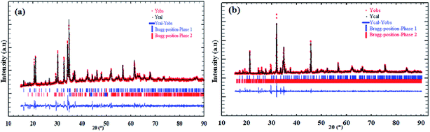 |
| | Fig. 1 Graphical results of the Rietveld refinement of synthesized Na2CoSiO4 by (a) ameliorate solid state method denoted NCS-SS, (b) co-precipitation method denoted NCS-CP. | |
Overall, Na/Li orthosilicate materials were indexed in primitive systems.19 NCS-SS was indexed successfully on the basis of an orthorhombic unit cell with the Pna21 space group. The corresponding cell parameters obtained from the data are as follows: a = 10.9549(7) Å, b = 5.2523(3) Å, c = 7.0440(6) Å, α = β = γ = 90°, V = 405.29(5) Å3 and Z = 4 with a reliability factor of χ2 = 1.8. The small peaks correspond to the impurity phase δ-Na2Si2O5 (3.6%).20 While NCS-CP has the same orthorhombic crystal structure, its space group is Pbca and its cell parameters correspond to: a = 10.3176 (2) Å, b = 14.6019 (7) Å, c = 5.1558 (2) Å, V = 771.85(3) Å3 and Z = 8 with a reliability factor of χ2 = 1.48. Based on the refinement, the relative amount of the NCS-CP phase is 96.88%. However, the relative amount of the γ-Na2Si2O5 impurity is 3.18%. Na2Si2O5 is frequently the minority impurity in the NCS compounds. The refined structural parameters of NCS-SS and NCS-CP and their impurities are summarized in Table 1. Both factors Rwp and RB which are the fit factors are reasonably small, indicating that the phases of sodium orthosilicate are appropriate structural models for Na2CoSiO4. The final atomic coordinates and the isotropic displacement parameters are listed in Table 2, while the bond angles and distances are given in Tables 3 and 4.
Table 1 Crystal data of the Na2CoSiO4 compound and the detected impurities
| Formula |
NCS-SS |
δ-Na2Si2O5 |
NCS-CP |
γ-Na2Si2O5 |
| Crystal system |
Orthorhombic |
Monoclinic |
Orthorhombic |
Monoclinic |
| Space group |
Pna21 |
P121/c1 |
Pbca |
C12/c1 |
| Formula units (Å) |
a = 10.9549(7) |
a = 8.3993(2) |
a = 10.3176(2) |
a = 33.3766(11) |
| b = 5.2523(3) |
b = 12.083(3) |
b = 14.6019(7) |
b = 14.0877(5) |
| c = 7.0440(6) |
c = 4.843(1) |
c = 5.1558(2) |
c = 26.1507(7) |
| α = β = γ = 90° |
α = γ = 90°, β = 90.37(3) |
α = β = γ = 90° |
α = γ = 90°, β = 108.60° |
| Rp (%) |
27.6 |
27.6 |
25.6 |
25.6 |
| Rwp (%) |
25.6 |
25.6 |
23.6 |
23.6 |
| Rexp (%) |
19.10 |
19.10 |
19.37 |
19.37 |
| RB |
3.462 |
2.245 |
2.384 |
3.129 |
| Rf |
2.679 |
2.046 |
2.047 |
3.117 |
| χ2 |
1.79 |
1.79 |
1.48 |
1.48 |
| % |
96.4 |
3.6 |
96.88 |
3.18 |
Table 2 Fractional atomic coordinates and equivalent isotropic displacement parameters of Na2CoSiO4
| Atom |
Wyck |
x |
y |
z |
Occ |
| NCS-SS |
| Co(1) |
4a |
0.15484 |
0.25746 |
0.63431 |
1 |
| Si(2) |
4a |
0.40688 |
0.26700 |
0.10603 |
1 |
| Na(1) |
4a |
0.17294 |
0.23567 |
0.10603 |
1 |
| Na(2) |
4a |
0.40630 |
0.26710 |
0.36897 |
1 |
| O(1) |
4a |
0.32064 |
0.24200 |
0.69309 |
|
| O(2) |
4a |
0.09690 |
0.44781 |
0.40866 |
|
| O(3) |
4a |
0.04951 |
0.28720 |
0.88692 |
|
| O(4) |
4a |
0.14226 |
0.88014 |
0.57608 |
|
![[thin space (1/6-em)]](https://www.rsc.org/images/entities/char_2009.gif) |
| NCS-CP |
| Co(1) |
8c |
0.97150 |
0.81450 |
0.70095 |
0.5 |
| Si(1) |
8c |
0.97150 |
0.81450 |
0.70095 |
0.5 |
| Co(2) |
8c |
0.26550 |
0.05584 |
0.27810 |
0.5 |
| Si(2) |
8c |
0.26550 |
0.05584 |
0.27810 |
0.5 |
| Na(1) |
8c |
0.48810 |
0.06810 |
0.68160 |
0.5 |
| Na(2) |
8c |
0.50450 |
0.04080 |
0.77420 |
0.5 |
| Na(3) |
8c |
0.74650 |
0.31280 |
0.18090 |
0.5 |
| Na(4) |
8c |
0.79510 |
0.30730 |
0.37460 |
0.5 |
| O(1) |
8c |
0.06560 |
0.91190 |
0.80300 |
|
| O(2) |
8c |
0.01920 |
0.78010 |
0.42380 |
|
| O(3) |
8c |
0.23960 |
0.95950 |
0.12760 |
|
| O(4) |
8c |
0.79130 |
0.83870 |
0.84560 |
|
Table 3 Selected distances of Na2CoSiO4 (Å)
| NCS-SS |
NCS-CP |
| Bond distances (Å) |
Bond distances (Å) |
| Co1–O1 |
1.865 |
Co1–O4 |
2.034 |
| Co1–O2 |
1.982 |
Co1–O1 |
1.801 |
| Co1–O3 |
2.127 |
Co1–O2 |
1.863 |
| Co1–O4 |
2.028 |
Si1–O2 |
1.593 |
| Si1–O1 |
1.603 |
Co2–O1 |
1.810 |
| Si1–O2 |
1.693 |
Co2–O3 |
1.817 |
| Si1–O3 |
1.590 |
Si2–O4 |
1.767 |
| Si1–O4 |
1.621 |
Si2–O3 |
1.629 |
Table 4 Selected angles of Na2CoSiO4 (°)
| NCS-SS |
NCS-CP |
| Atoms (1, 2, 3, 4) |
Atoms (1, 2, 3, 4) with M = Co/Si |
| O1–Co1–O4 |
93.93 |
O2–M1–O4 |
98.29 |
| O3–Si1–O2 |
80.80 |
O4–M2–O1 |
96.78 |
| O1–Si1–O2 |
90.78 |
O1–M2–O3 |
89.41 |
| Co1–O1–Na2 |
99.34 |
O1–Na1–O3 |
69.44 |
| Co1–O2–Na2 |
97.78 |
O3–Na1–O1 |
99.74 |
| Co1–O4–Na2 |
95.16 |
O4–Na4–O2 |
96.29 |
| Na1–O4–Na2 |
92.28 |
M2–O1–Na2 |
92.52 |
| O1–Co1–O3 |
110.24 |
M2–O1–Na1 |
94.31 |
| O2–Co1–O4 |
107.99 |
M2–O1–Na1 |
88.32 |
| O2–Co1–O3 |
117.40 |
M1–O1–Na1 |
75.23 |
| O4–Co1–O3 |
101.78 |
M1–O2–Na4 |
86.58 |
| O1–Co1–O2 |
120.79 |
M2–O3–Na4 |
82.45 |
| O3–Si1–O1 |
127.11 |
M2–O3–Na1 |
93.79 |
| O3–Si1–O4 |
110.48 |
Na4–O3–Na1 |
71.28 |
| O1–Si1–O4 |
122.20 |
Na3–O3–Na1 |
81.88 |
| O4–Si1–O2 |
103.69 |
M1–O3–Na3 |
81.88 |
| O3–Na1–O4 |
119.39 |
O2–M1–O1 |
110.16 |
| O4–Na2–O2 |
116.49 |
O2–M1–O2 |
103.76 |
| O4–Na2–O1 |
141.68 |
O2–M1–O4 |
131.77 |
| O2–Na2–O1 |
101.44 |
O1–M1–O2 |
105.25 |
| Si1–O1–Co1 |
138.50 |
O1–M1–O4 |
104.39 |
| Si1–O1–Na2 |
120.95 |
O3–M2–O4 |
121.76 |
| Si1–O2–Co1 |
128.05 |
O3–M2–O1 |
114.62 |
| Si1–O2–Na2 |
115.50 |
O3–M2–O3 |
111.18 |
| Si1–O3–Na1 |
130.89 |
O4–M2–O3 |
117.13 |
| Si1–O3–Co1 |
118.66 |
O1–Na1–O1 |
104.77 |
| Na1–O3–Co1 |
105.06 |
O4–Na3–O3 |
102.86 |
| Si1–O4–Co1 |
123.80 |
O4–Na3–O4 |
119.65 |
| Si1–O4–Na1 |
105.41 |
O3–Na3–O4 |
134.20 |
| Si1–O4–Na2 |
129.24 |
O3–Na4–O4 |
147.93 |
| Co1–O4–Na1 |
104.97 |
O3–Na4–O2 |
106.07 |
| |
|
M1–O1–M2 |
134.75 |
| |
|
M1–O1–Na2 |
120.60 |
| |
|
M1–O1–Na1 |
104.18 |
| |
|
M1–O1–Na1 |
125.19 |
| |
|
M2–O1–Na1 |
106.90 |
| |
|
M1–O2–M1 |
134.88 |
| |
|
M1–O2–Na4 |
137.91 |
| |
|
M2–O3–M2 |
125.72 |
| |
|
M2–O3–Na4 |
151.79 |
| |
|
M2–O3–Na3 |
125.03 |
| |
|
M2–O3–Na1 |
104.50 |
| |
|
M2–O3–Na3 |
107.73 |
| |
|
M2–O4–Na3 |
117.06 |
| |
|
M2–O3–M1 |
108.80 |
| |
|
M2–O3–Na4 |
134.27 |
| |
|
M2–O3–Na3 |
128.42 |
| |
|
Na3–O3–M1 |
120.68 |
| |
|
M1–O3–Na4 |
102.45 |
3.2. Description of the NCS structures
Na2MSiO4 (M = Fe, Mn, Co) is classified among the C-type compounds. It crystallized in the three-dimensional (3D) frameworks of the CoO4 and SiO4 tetrahedral units.21 The structure of Na2CoSiO4 deviated from the orthorhombic arrangement because of the different sizes of the Na, Co and Si atoms and their tetrahedral coordination. The powder pattern of Na2CoSiO4 indicates that it is isostructural with the Na2BeSiO4 structure.22,23
The structure can be considered as a ‘stuffed’ cristobalite with corner-sharing alternate transition metal and silicon tetrahedral units. In general, the orthosilicates are characterized by tetrahedral anion units, in particular (SiO4)4−, covalently bonded to the MO4 polyhedra.24,25 The relative orientation of the tetrahedra and the degree of corrugation in the layers differ considerably according to the modification.
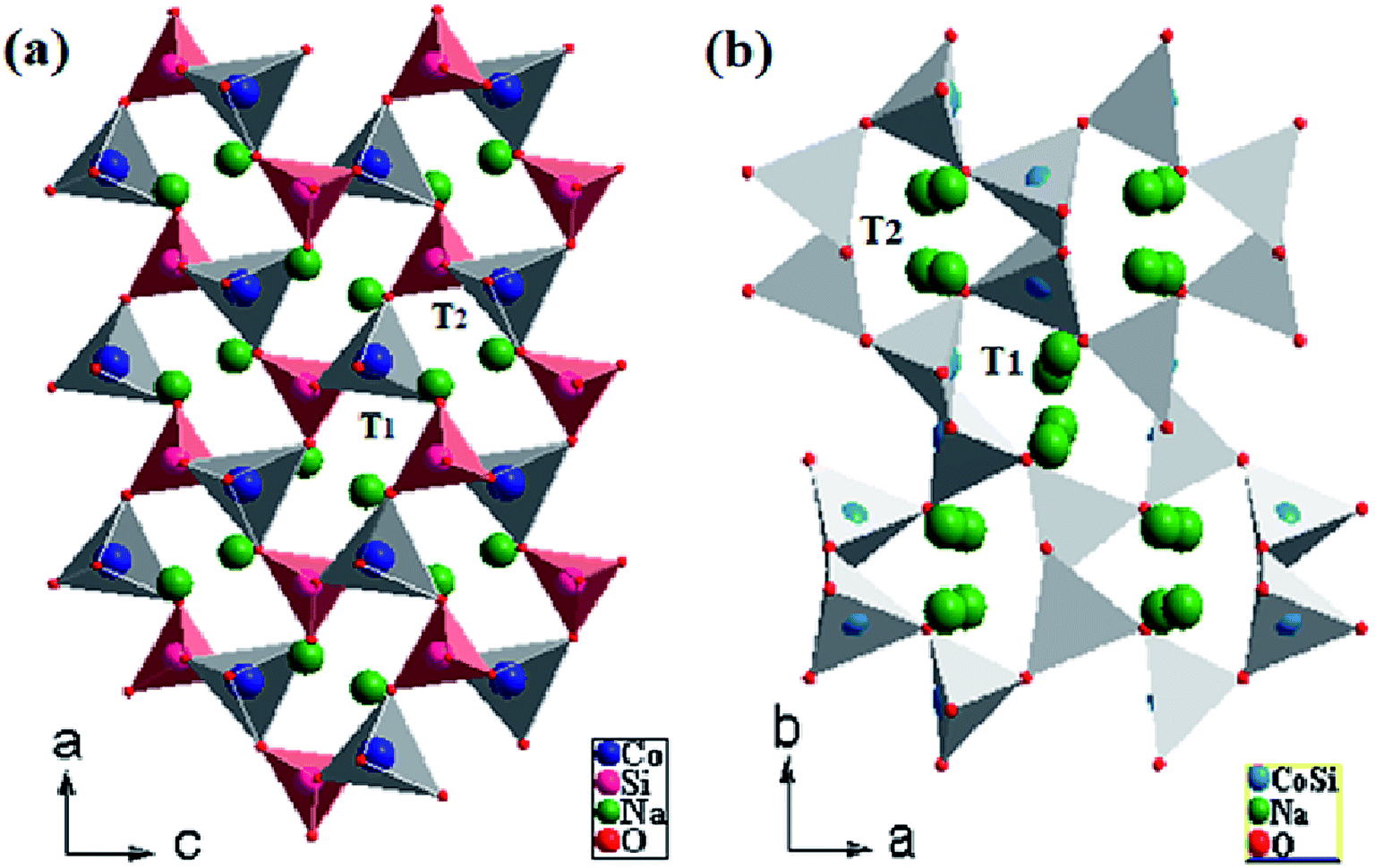
The Pna21-Na2CoSiO4 structure can be viewed as a build-up of infinite zig–zag paths alternating (CoO4)4− and (SiO4)4− in the (c, b) plan. These tetrahedra built up a network with channels along the a axis in which the Na+-ions were arranged as represented in Fig. 2(a). In the periodic structure, half the CoO4 and SiO4 tetrahedra pointed along (100), while the other half pointed in the opposite direction (−100) in an alternate manner and were linked only by sharing corners. The mechanism process was induced by the parallel displacement of Na+-ions along the c axis. It consists of double chains of deformed (CoO4)4− tetrahedra that were parallel-propagated in the (a, c) plan and interlinked partially by corner-sharing. Each (SiO4)4− group was thus surrounded by four (CoO4)4− tetrahedra and vice versa, ultimately forming cavities. The average values of the bond lengths of Si–O and Co–O in the (SiO4)4− and (CoO4)4− tetrahedra are 1.6465 Å and 2.0025 Å respectively (Table 3). Moreover, it is clear that the average bond lengths of Co–O in (CoO4)4− tetrahedra were much larger than those of Si–O in the (SiO4)4− tetrahedra. Na(1) and Na(2) ions occupied the tetrahedral sites located between two [SiO4–CoO4]4− layers. Other paths with longer Na–Na hop distances should yield high migration for batteries around 3 Å. Regarding the Na(1) and Na(2), they were arranged along (100). Moreover, it is very important to note that Na(1) and Na(2) were trapped in two antiparallel cavities (T1 and T2) (Fig. 2(a)). This result would have a great influence on the migration process of Na+-ions.
 |
| | Fig. 2 Na2CoSiO4 structures as a ‘stuffed cristobalite’ with corner sharing CoO4 tetrahedra connected via SiO4 tetrahedra (a) NCS-SS and (b) NCS-CP. | |
The Pbca-Na2CoSiO4 is similar to the structure published by J. C. Treacher et al.15 The positions of Co2+, Si4+ cations in NCS-CP show that silicon and cobalt occupied the same site (Fig. 2(b)). Na+ cations were stuffed onto the vacant tetrahedral sites. All tetrahedra were not oriented in the same way. The results presented here demonstrate that future work should consider how to exploit the importance of cavities. Since the tetrahedra around the Na atoms only shared corners with neighboring Na cavity, and since the tetrahedra of the Si and Co atoms were fully occupied and smaller than the Na tetrahedra, the diffusion of Na+-ions must proceed through the unoccupied tetrahedral sites in the structure. Eventually, forming the parallel and antiparallel cavities (T1, T2) played the main role in the structure and clearly drove the system. In the present work, the different space groups could be expressed either Co and Si sources or the different sintered temperature (900° for NCS-SS and 600° for NCS-CP).
3.3. Scanning electron microscopy
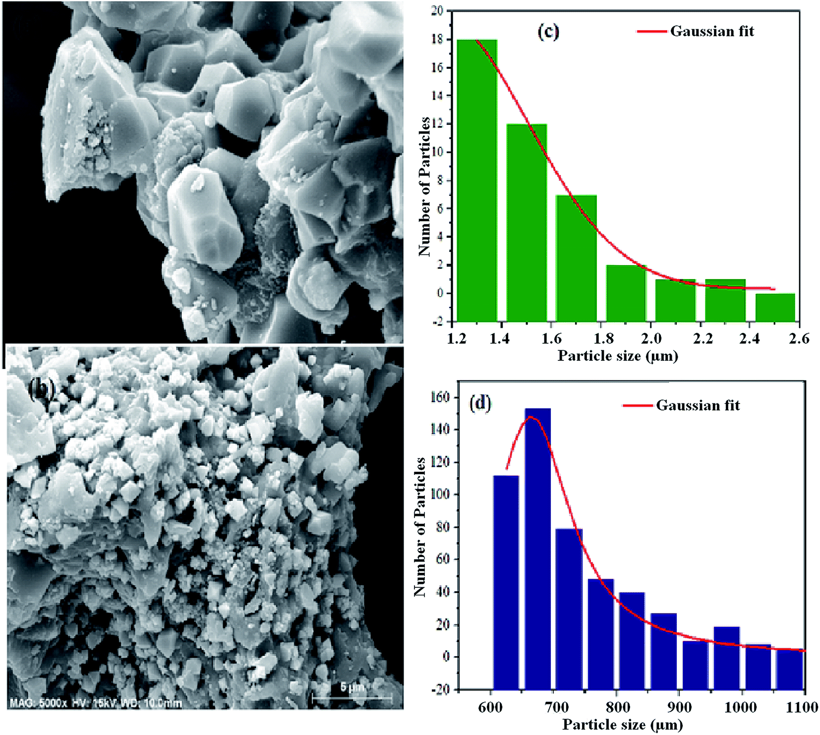
Besides the crystallographic structure, the morphological features are important to reinforce and bring out the dielectric mechanism of the material. Thus, we have studied the morphological characteristics of the prepared powders. The SEM micrographs of the NCS-SS and NCS-CP are presented in Fig. 3. The SEM images of the two samples were clearly constituted of an agglomeration of the small particles which led to sub-micrometer particles. This could be due to the relatively high calcination temperature (900 °C) and (600 °C) for NCS-SS and NCS-CP respectively. The measured sizes of the particles are 1.4 μm for NCS-SS and 0.7 μm for NCS-CP. Furthermore, in both Na2CoSiO4 samples, we could observe the presence of small-sized particles defined as secondary particles. Consequently, the presence of these particles may improve the charge storage through the reduction of migration path lengths.26 Hence, the formation of micro-sized particles, hollow structure and morphology density are beneficial as electrode material for secondary batteries.27
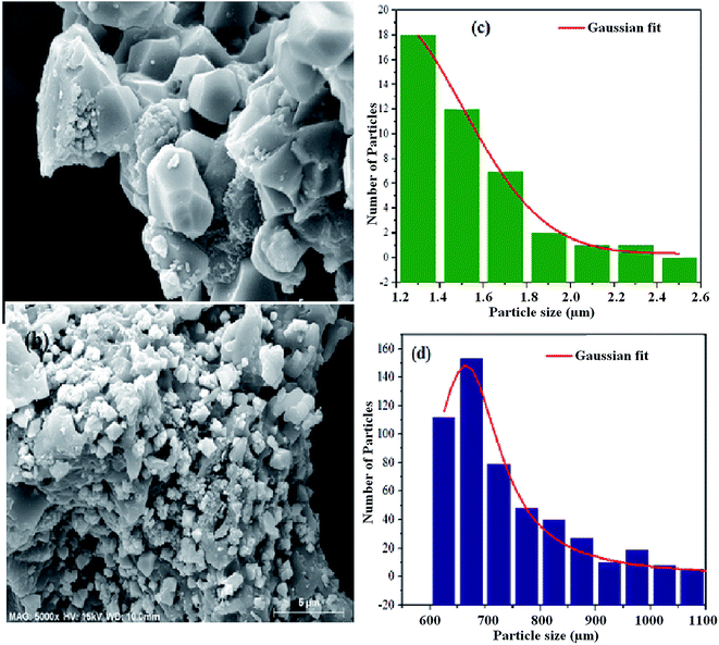 |
| | Fig. 3 SEM micrograph of the fractured surface of NCS-SS (a) and NCS-CP (b) samples heat treated at 900 °C and 600 °C under argon. The corresponding particle size histograms (c and d) are presented in the right of the figure. | |
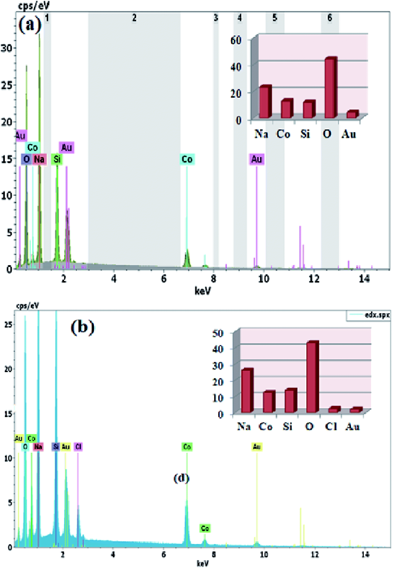
On the other hand, the SEM and EDS link the surface morphology to its chemical composition. The EDS spectra were taken at several points on the surface of the samples. In Fig. 4(a) and (b), the existing elements are illustrated in the EDS spectra. In order to measure the stoichiometry of each element, the EDS analysis was carried out. The individual atoms such as Na, Co and Si were observed in the EDS spectra suggesting homogeneous distribution of the elements. Moreover, the ratios of atoms for Na, Co, Si and O were very close to the stoichiometric ratio of both Na2CoSiO4 samples which in turn supported the determination of the purity of the Na2CoSiO4 particles together with the powder XRD. It is interesting to note that Cl−-ion was directly observed with a small percentage in the surface layer of NCS-CP. The result is very close to its theoretical composition ratio 2:1:1.
 |
| | Fig. 4 EDX spectra of the fractured surface of NCS-SS (a) and NCS-CP (b) samples sintered at 900 °C and 600 °C, respectively. | |
3.4. Dielectric relaxation
We have adopted the permittivity formalism to study the relaxation mechanism and to explore the ion dynamics in the NCS compounds at different temperatures and frequencies. The real (ε′) and imaginary (ε′′) parts of the complex permittivity for NCS-SS and NCS-CP are plotted in Fig. 5(a)–(d) as a function of angular frequency ω (ω = 2πf) at various temperatures. Both ε′ and ε′′ attained a minimum value at high frequencies irrespective of the temperature. The mounting value of ε′ with the climb of temperature might be attributed to the rise in the process of space charge polarization. With the increasing frequency (when ω < 1/τ), dipoles began to lag behind the field and ε′ slightly decreased. When the frequency reached the characteristic frequency (ω = 1/τ), the dielectric constant dropped and demonstrated the relaxation process. At very high frequencies (ω ≫ 1/τ), dipoles could no longer follow the field. Thus, the increasing value of ε′ in the high and mid frequency regions was associated with the dipolar polarization (Na+-ions). The high values of ε′ at a relatively low frequency might be due to the extrinsic contribution (the space charge localization at NCS). It seems clear that NCS-SS presents three contributions. The two contributions at high and mid frequencies were shown by two types of charge carriers (Na+-ions) which were responsible to move only over short distances. This process was in agreement with the existence of two types of cavities in both NCS materials. The third contribution corresponded to the process of space charge polarization at low frequencies. At high frequency, NCS-CP has demonstrated a weak appearance of the relaxation peaks. According to Fig. 5(b) and (d), ε′′ increased with mounting temperature, which reveals the dipolar molecular dynamics at high and medium frequency ranges. Typically, the dielectric constant shifted toward high frequencies with the increase in temperature, exhibiting a thermally activated behavior. Moreover, the rise in temperature brought thermal agitation in the compounds, which can produce a deformation cavity.28 Consequently, the mobility of the ions increased. The corresponding variation of the dielectric loss as a function of the angular frequency has been investigated. Fig. 6(a) and (b) display the tanδ spectra. We can see that three clear peaks were detected in the frequency dependence of the dielectric loss for NCS-SS and two peaks one of which was too weak to be observed for NCS-CP. For the NCS-SS material, when the temperature climbed, the first relaxation (A) disappeared at high frequencies between 1 × 10⁶ to 3.8 × 10⁴ Hz. At mid frequency, the second relaxation (B) between 2.4 × 10⁴ and 1.4 × 10³ Hz spread to high frequencies when the temperature went up. Meanwhile, the third relaxation (C) appeared at a certain low frequency below 200 Hz and in a high temperature region. Since the relaxation maximum shifted monotonically to low temperatures with decreasing frequency, we could attribute this dielectric dispersion phenomenon to a thermally-activated process. The relaxation time for the medium and high frequency relaxations was very close. For NCS-CP, two clear peaks are observed in the frequency dependence of the dielectric loss as shown in Fig. 6(b). The first one occurred at mid frequency range 500–3700 Hz (relaxation B) and the second was presented at high frequency range 8 × 10³–5 × 10⁵ Hz (relaxation A). The relaxation peaks moved toward high frequencies with the increase in the temperature, indicating that the relaxation processes in both NCS samples are temperature dependent. In the main processes, the Na and O positions were quite dynamic, while the Co–Si network remained relatively undisturbed to maintain the stability of the structure as a function of temperature. Accordingly, understanding the distinction of the relaxation process between NCS-SS and NCS-CP provides a more comprehensive image of the system dynamics and the transport mechanisms. First, NCS-SS (with the Pna21 space group) had lower local Na coordination symmetry than NCS-CP (with the Pbca space group) which was caused by the different silicon and cobalt sources.29,30 Second, the NCS-SS material presented two different charge carriers Na(1) and Na(2) in two equivalent cavities. However, NCS-CP presented four charge carriers Na(1), Na(2), Na(3) and Na(4) in two non-equivalent cavities.31 The Na+ environment in NCS-CP was more congested than NCS-SS, because of the duplication of Si and Co and the presence of Cl−.
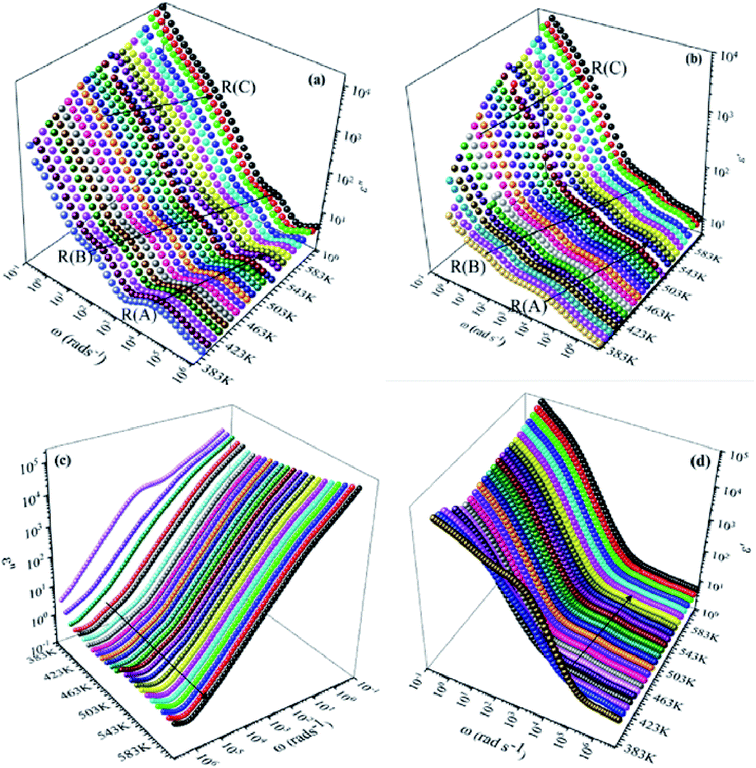 |
| | Fig. 5 Dielectric loss ε′′ and dielectric constant ε′ as a function of frequency for NCS-SS (a and b) and NCS-CP (c and d) at various temperatures ranging from 383 K to 613 K with the interval of 10 K. | |
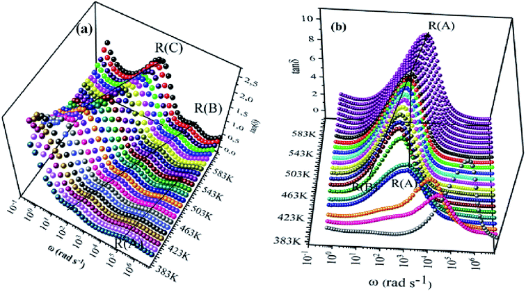 |
| | Fig. 6 Frequency dependence of tanδ at various temperatures for NCS-SS (a) and NCS-CP (b) as a function of temperature. | |
We notice that the Coulombic attraction and the network are based on the increase in Na+, but the effect of the cation–cation repulsion and the steric effects can facilitate the jump of the Na+-ions along the canals. In this context, the above-listed results also imply that the Na-ions are less tight in NCS-CP than in NCS-SS, especially that the volume of NCS-SS (405.30 Å3) is lower than NCS-CP (771.74 Å3). Therefore, the connection of Na polyhedra leads to a flat energy landscape for sodium cations, which is beneficial for ion transport. As these sites are supposed to be metastable for the migration of sodium-ions, the migration energy barriers of sodium-ions depend on the crystallographic sites. In fact, the higher Na–O average bond distances (2.2587 Å) in NCS-SS with respect to in the NCS-CP ones (2.2632 Å) induces a decreasing of the attraction force between Na+ and O2− and the ions becomes less attached to the crystal.
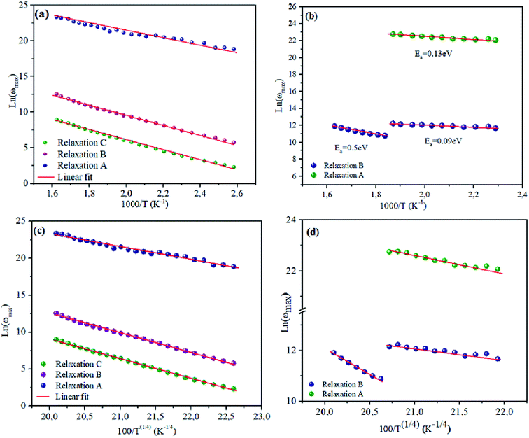
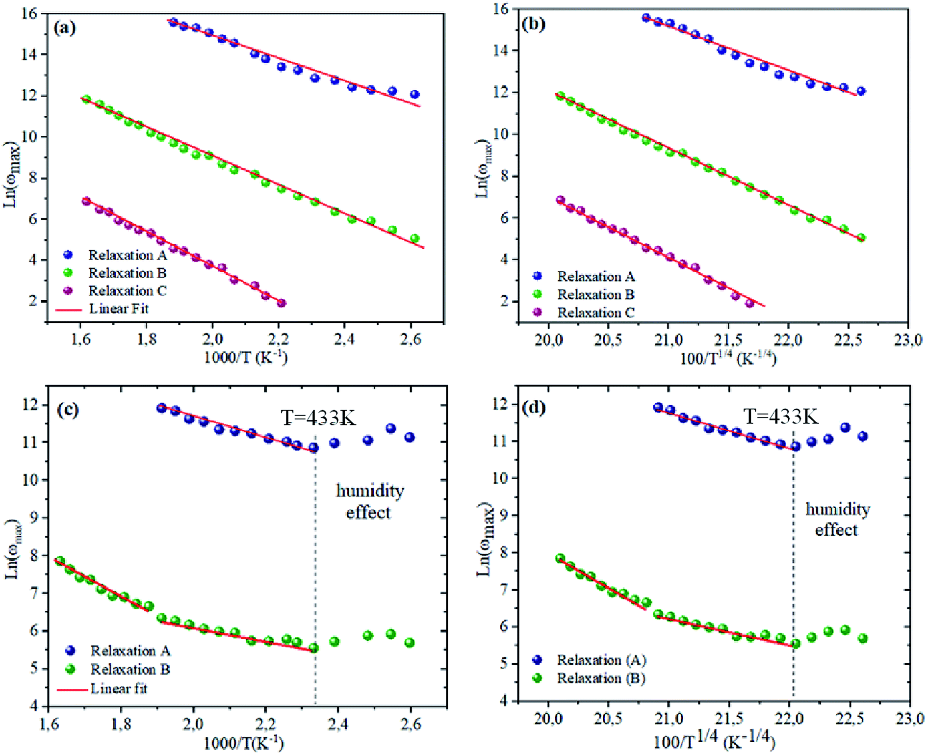
3.5. Activation energy
To bring out the relaxation response in the prepared materials, it is necessary to find the activation energy of the relaxation process for each composition. Fig. 7(a) and (b) are plotted the variation of ln(ωmax) as a function of the reciprocal of the temperature. A thermally-activated relaxation process is observed in both samples and confirms the semiconducting characteristic of samples. Notably, a humidity effect appears at around T = 533 K for NCS-CP sample.
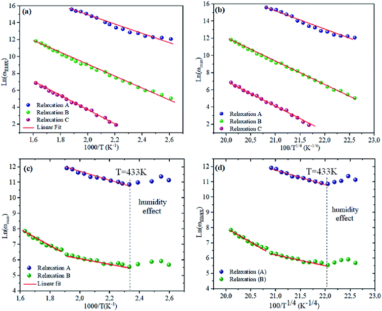 |
| | Fig. 7 (a and c) dependence of relaxation frequency ω on temperature with ln(ωmax) vs. 1000/T. The solid lines are the best-fitting results according to eqn (2). (b and d) The dependence of the relaxation frequency ω on temperature with ln(ωmax) vs. 100/T1/4. The solid lines are the best-fitting results according to eqn (3). | |
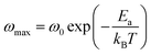
The ωmax data were fitted using the Arrhenius law equation:32
| |
 | (2) |
where
Ea is the activation energy required for the thermally-activated process,
ω0 represents the pre-exponential factor and
kB is the Boltzmann constant. The activation energy is presented in
Table 5. It is notable that the activation energies of NCS-SS were higher than those of NCS-CP. The experimental data exhibits a deviation from the Arrhenius law in several materials, which shows the polaron relaxation related to localized charge carriers.
33–37
| Relaxation |
NCS-SS |
NCS-CP |
| Relaxation A |
0.45 eV |
0.25 eV |
| Relaxation B |
0.59 eV |
0.41 eV (at high temperature) |
| 0.18 eV (at low temperature) |
| Relaxation C |
0.71 eV |
|
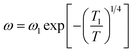
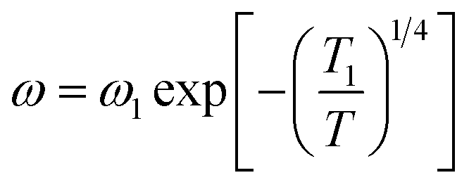
Moreover, a Mott's variable-range-hopping mechanism for polarons could fit better as described by eqn (3).38
| |
 | (3) |
where
ω1 and
T1 are two fitting constants. The solid lines of this model are shown in the inset of
Fig. 7(c) and (d). The values
T1 for NCS-SS were 2.18 × 10
7 K, 5.12 × 10
7 K and 8.31 × 10
7 K for relaxations (A), (B) and (C) respectively. The values for NCS-CP were determined to be 1.8 × 10
7 K for relaxation (A) and 7.59 × 10
7 K between 533 K and 613 K as well as 8.4 × 10
7 K below 533 K for relaxation (B). The
T−1/4 law confirmed the polaron relaxation in NCS samples.
11,39 The quasiparticle (polaron) could move between different vacant sites.
The transition energy of a polaron can be expressed by the following equation:11
The hopping energy W calculated by eqn (4) increased from 0.15 eV at 383 K to 0.19 eV at 533 K for the relaxation (A), from 0.15 eV at 383 K to 0.22 eV at 613 K for the relaxation (B) and from 0.2 eV at 453 K to 0.25 eV at 613 K for NCS-SS. The sample NCS-CP exhibited the same behavior. The W values were found to be 0.21–0.26 eV below 513 K and 0.21–0.24 eV at high temperature for the relaxation (A) and 0.79–0.89 eV for the relaxation (B). The activation energy for the relaxation indicates that the relaxation mechanism for the two NCS materials is associated with polaron hopping based on charge carriers in order to account for the origin of a dielectric relaxation observed in NCS-SS and NCS-CP. These results hint that the sodium-ions over these sites probably pass from Na(4a) for NCS-SS and Na(8c) for NCS-CP to other sites.
3.6. Frequency and temperature dependence of the electric modulus formalisms
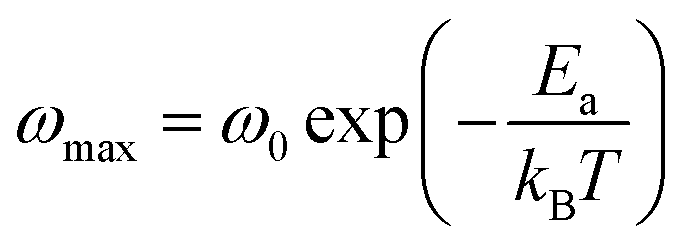
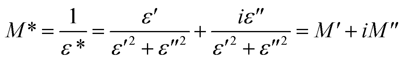
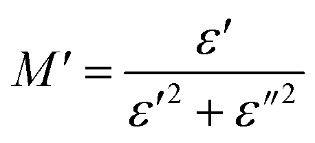
To emphasize the relaxation phenomena, a study of the complex modulus at various temperatures was carried out in the same frequency range. The electric modulus was employed to investigate the polaron relaxation and to avoid the dynamical aspects of the electrical transport phenomena in the NCS samples.40 The complex electric modulus (M*) could be calculated by the conversion formula (eqn (5)) using the complex dielectric constant (ε*), which is defined by:| |
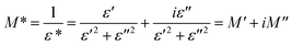 | (5) |
where  is the real part of complex modulus and
  is the imaginary part of the complex modulus.
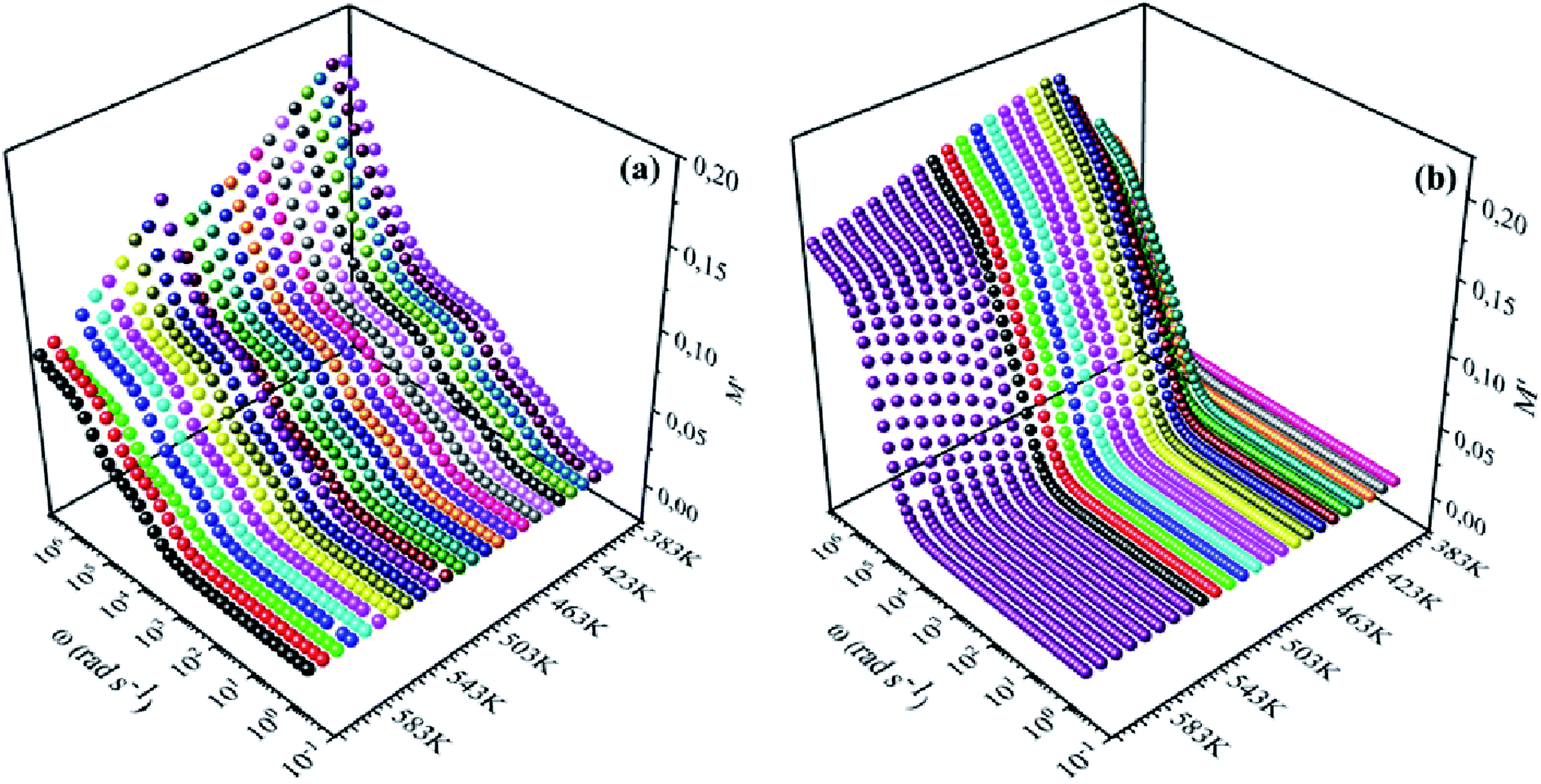
Fig. 8(a), (b), 9(a) and (b) show the variation of the real and imaginary parts of the modulus as a function of angular frequency at various temperatures for NCS-SS and NCS-CP. At low frequencies, M′ exhibited very small values and tended to zero and, thus, suggesting the suppression of the electrode polarization effect.41 As the frequency increased, M′ climbed to a maximum asymptotic value defined as  due to the distribution of relaxation processes over a range of frequencies. Both samples produced a two-step decrease in M′ in the measured temperature range, while the NCS-CP peaks shifted to one step above 533 K. Correspondingly, M′′ showed two peaks in the same temperature range. The modulus spectra presented different relaxation mechanisms which depend upon temperature and frequency regions. We observe that NCS-SS appearing in M′′ along the temperature ranges. NCS-CP revealed two peaks, which shifted to a single peak at high temperature. To distinguish localized dielectric relaxation processes, R. Gerhardt proposed two ways: as far as NCS-CP is concerned, this material presented a pure conduction process (relaxation B), which could be seen as a relaxation peak observed in the frequency spectra of the imaginary component M′′ and no clear peak appeared in the corresponding plot of ε′ and ε′′, while for relaxation A, this sample (NCS-CP) showed weak peaks of ε′ and ε′′. This mixed process was related to the presence of two charges carriers (Na+). As regards NCS-SS, this material indicated a dielectric relaxation process as the relaxation peaks appeared in all the representations of M′′, tanδ, ε′ and ε′′.42,43 The peaks at low and high temperatures might be attributed to the existence of dissociate Na-ions or steady species caused by linked Na in NCS samples. Whilst, the peak overlap (above 533 K) is attributed either to cavity deformation or the two charge carriers Na+ are the same response at high temperatures in NCS-CP.44,45 The spectra of M′′ peaks at both high and mid frequencies suggest that two processes contribute to the diffusion of two Na charge carriers. One of these processes relaxed at the high frequency region but the contribution of the other process appeared as a peak in the mid frequency region. The values of
  shifted to the high frequency values with the increase in the temperature. The imaginary part of the electric modulus in different temperatures has been fitted with the function proposed by Bergman:46
| |
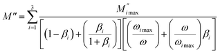 | (6) |
where the

is the maximum peak value of
M′′,
ωmax is the corresponding frequency and the index
β indicates the degree of deviation from the Debye-type relaxation.
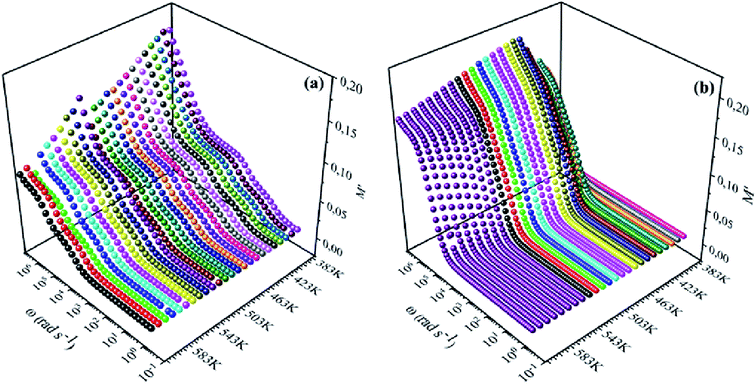 |
| | Fig. 8 Frequency dependence of real of electric modulus (M′) for (a) NCS-SS and (b) NCS-CP at various temperatures. | |
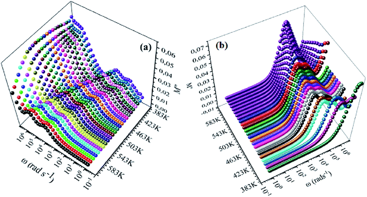 |
| | Fig. 9 Frequency dependence of imaginary of electric modulus (M′′) for NCS-SS (a) and NCS-CP (b) at various temperatures. | |
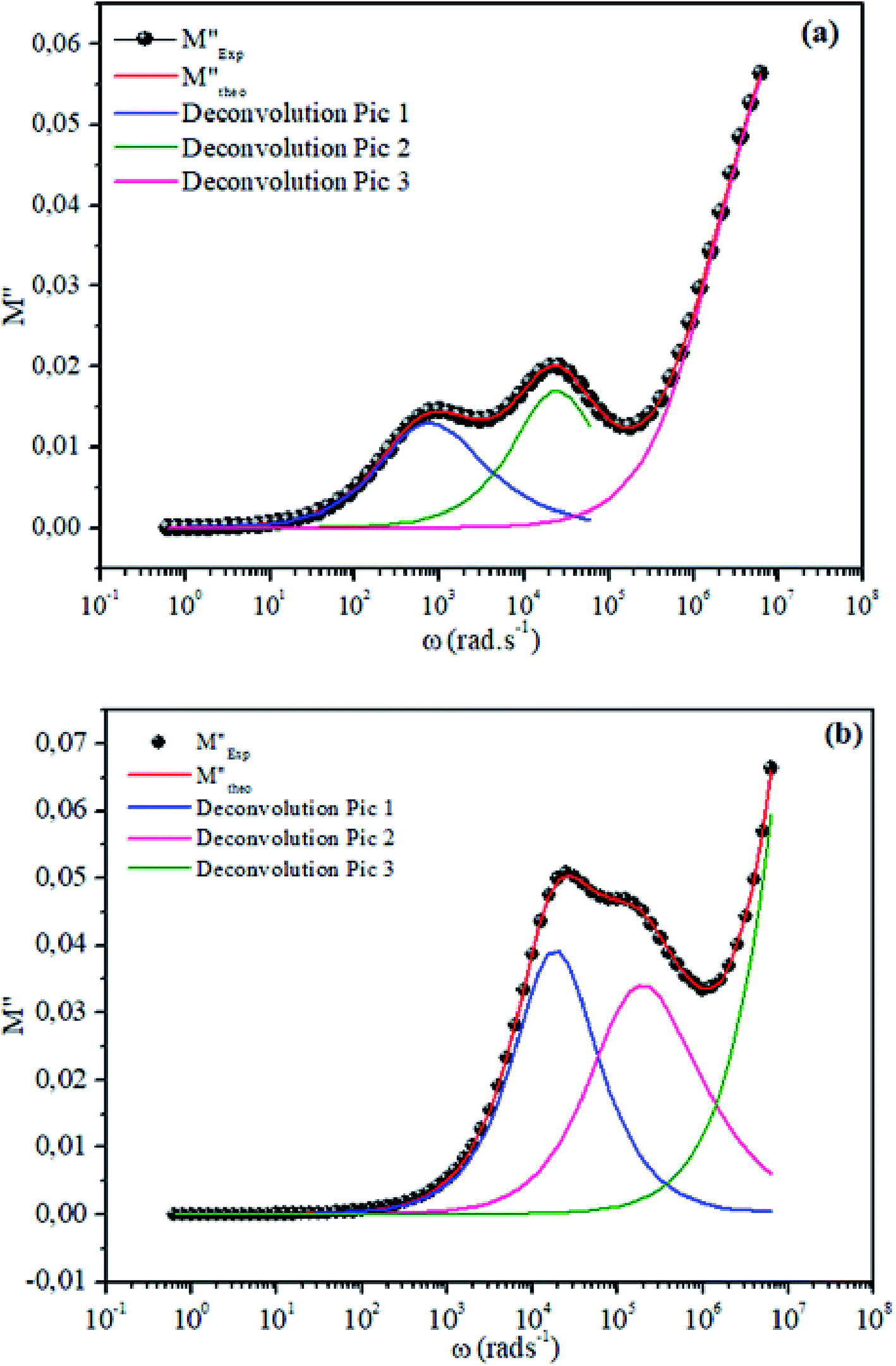
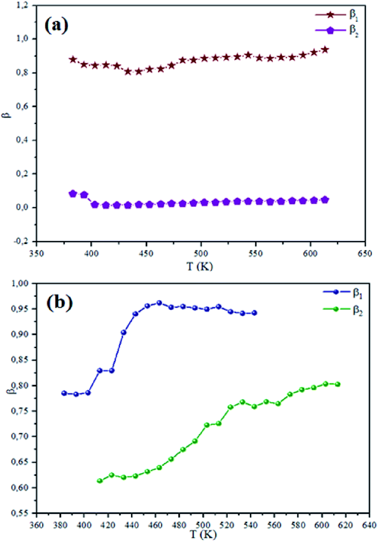
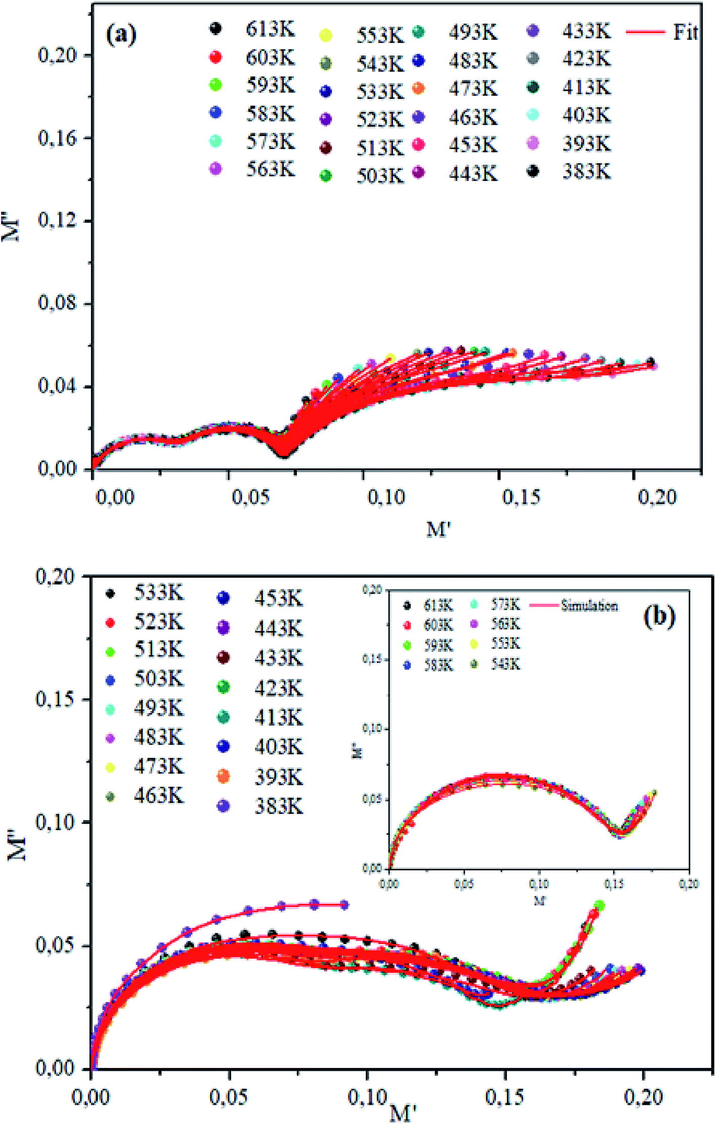
The theoretical fit and peak deconvolution (eqn (6)) of the experimental data are shown by solid lines in Fig. 10(a) and (b). It can be seen that the model fits the experimental data very well. The fit values of β (β < 1) suggest a non-Debye-type dielectric relaxation.47 Fig. 11 shows the dependence of β values on the variety of temperatures. For NCS-SS, β varied slightly in the temperature range which indicates stability of the number of Na-ions available for short distance conduction. This result suggests that the polarons are stable in the dielectric process with the increase in the temperature. NCS-CP demonstrated higher values of β2 when the value of β1 increased to 0.96 below 453 K, and then slightly decreased to 0.92 as soon as the temperature went up to 613 K. The increase in β implies that there is a decrease in the number of sodium-ions available for short distance conduction where Na+-ions have a higher probability of being attracted by Cl−-ions.48,49 The complex electrical modulus of the NCS-SS sample (Fig. 12(a)) displays three semicircles. At low and mid frequencies, the arcs were perfectly overlapped into a single master curve, indicating that the underlying conduction mechanism remains the same, while at high frequency, we can seem a dispersion phenomena. As a result, the different contributions are linked to the transport mechanism of Na+ in or between cavities T1 and T2. On the other hand, NCS-CP displays only one semicircle between 543 K and 613 K, while it shows two discarded semicircles below 533 K (Fig. 12(b)). This result confirms that cavity is deformed at high temperature. The increase of temperature facilitates the long-range hopping movement of charge carriers Na+. This result is confirmed by the representations of M′′ and tanδ as a function of the logarithmic frequency measured at 573 K. We can see in Fig. 13 that the peak positions of M′′ and tanδ were more similar for NCS-SS than for NCS-CP. Therefore, we distinguish that, the peak positions between M′′ and tanδ were overlapped for NCS-SS. This indicates that long range and localized relaxations occur simultaneously. However, for NCS-CP, the two peak positions were dissimilar indicating a delocalized or a long-range transport mechanism.50 The dielectric relaxations processes suggest that the diffusion pathway of two sodium-ions could migrate over the same trajectories.11 The shift of the relaxation peak corresponds to the relaxation process towards higher frequencies with an increase in temperature which brings out a thermally-activated dielectric relaxation.51 At any temperature, the frequency ωmax defines the relaxation time τω = 1. In order to obtain the required activation energy for the dielectric relaxation process, the corresponding graphs of M′′as a function of ω and T for various values of ωmax are shown in Fig. 14. The temperature dependence of the characteristic relaxation frequency satisfies the Arrhenius law given by;32
| |
 | (7) |
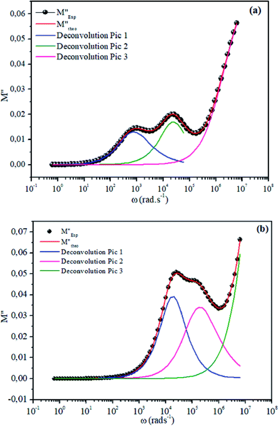 |
| | Fig. 10 Deconvolution of experimental imaginary parts of impedance (M′′) as a function of angular frequency for NCS-SS (a) and NCS-CP (b) at 513 K used eqn (6). | |
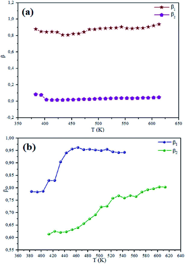 |
| | Fig. 11 Temperature dependence of the NCS-SS (a) and NCS-CP (b) at various temperatures. | |
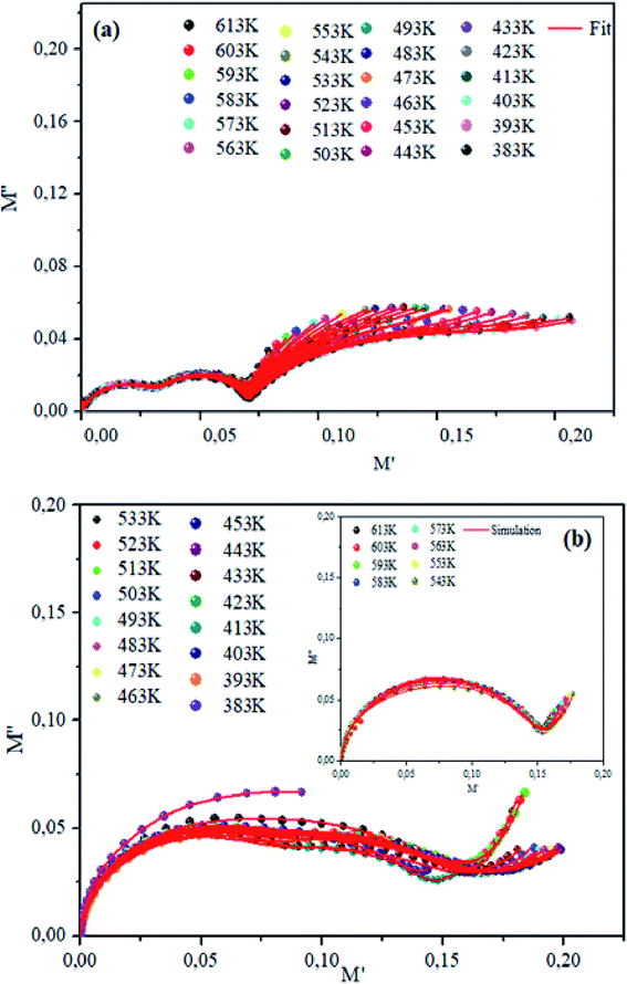 |
| | Fig. 12 Plots of imaginary modulus M′′ vs. M′ real modulus for NCS-SS (a) and NCS-CP (b) at various temperatures. | |
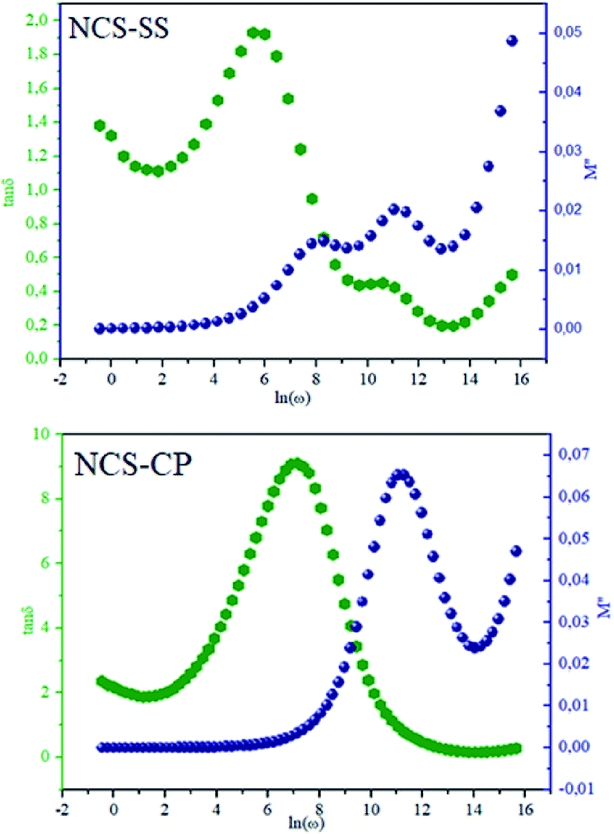 |
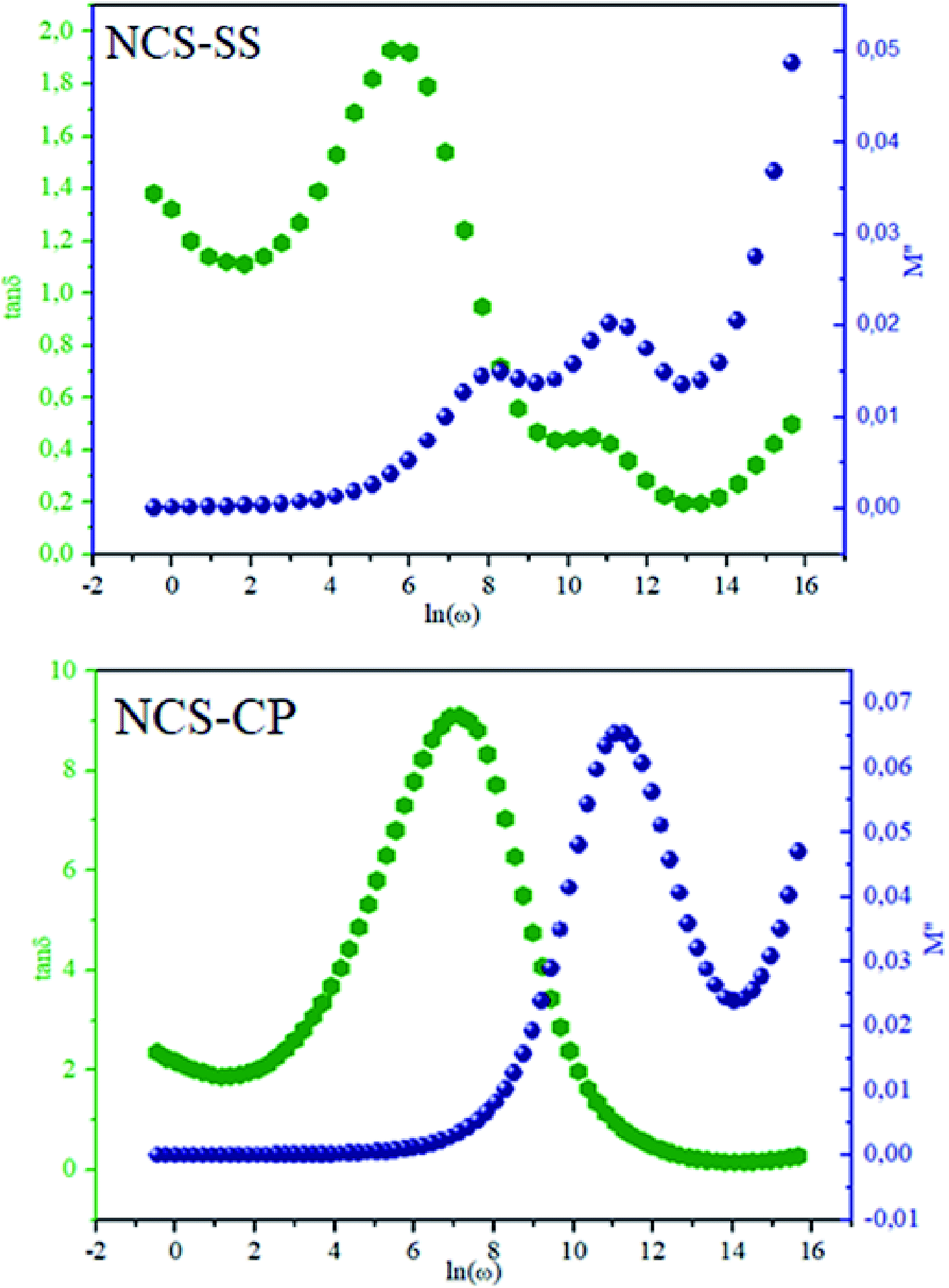
| | Fig. 13 Frequency dependence of relaxation peaks, M′′ and tanδ for the two NSC compounds at 573 K. | |
 |
| | Fig. 14 Dependence of relaxation frequency ω on temperature with lnωmax vs. 1000/T (a and b) and lnωmax vs. 100/T(1/4) (c and d) for NCS-SS and NCS-CP, respectively. | |
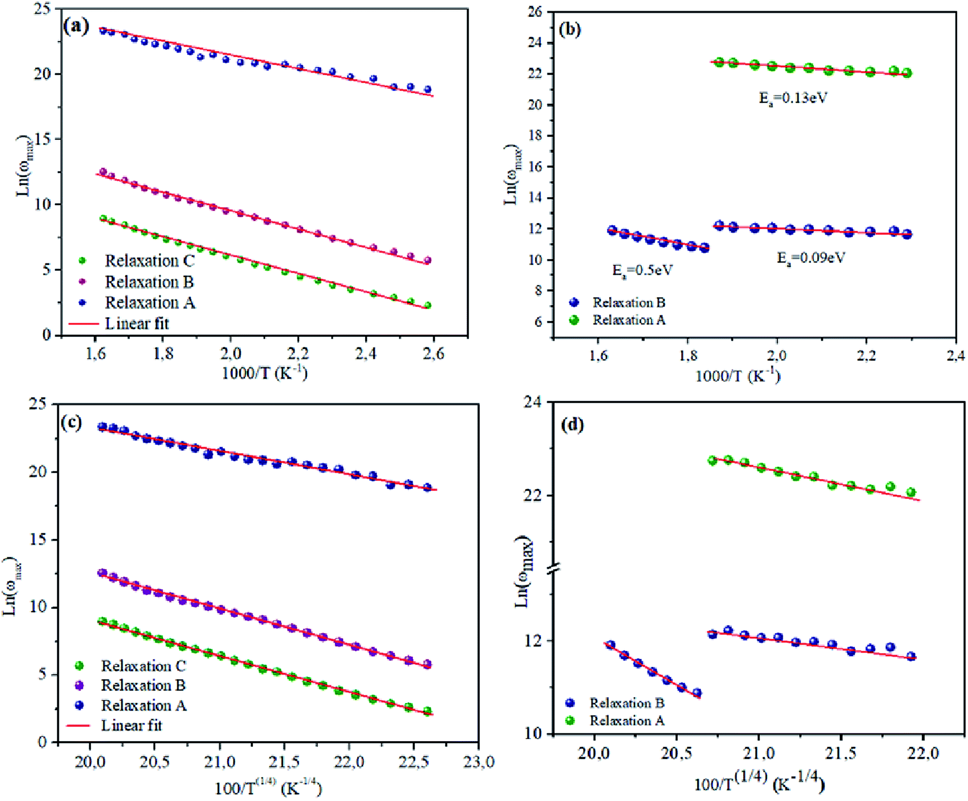
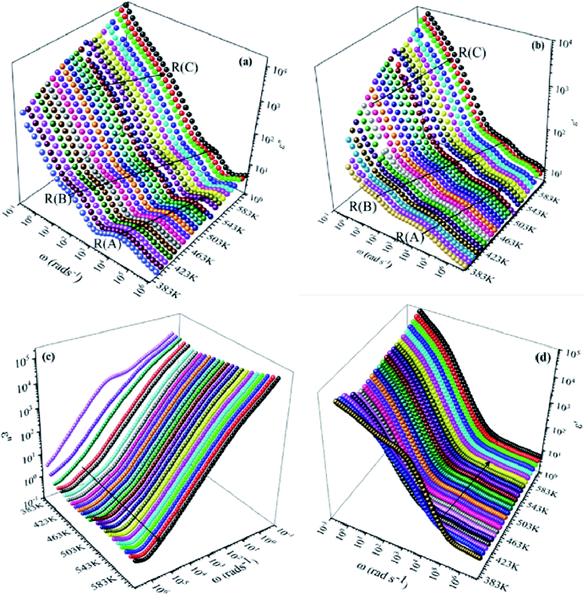
Consequently, it should be noted that Ea values which were obtained for the analysis of the results plotted in Fig. 14 were higher for NCS-SS than for NCS-CP. For the relaxation R(A), the calculated activation energies were 0.6 eV and 0.13 eV for NCS-SS and NCS-CP respectively. The Ea values for the relaxation R(B) were found to be 0.6, 0.59 eV and 0.5–0.09 eV for NCS-SS and NCS-CP respectively. The relaxation R(C) yielded 0.39 eV for NCS-SS. The variations of (ωmax) obey the same Arrhenius law of eqn (3) (Fig. 14(c) and (d)). The parameter T1 was calculated to be 4.7 × 10⁷ K, 5.15 × 10⁷ K and 8.98 × 10⁷ K for R(A), R(B), R(C) respectively in NCS-SS. These values were equal to the ones obtained by the dielectric loss. The similar behavior of the relaxation process between the modulus and tanδ indicates that they originated from the same mechanism. However, NCS-CP pointed to very different values from those obtained by tanδ. The parameter T1 was calculated to be 0.16 × 10⁷ K for R(A) and 1.51 × 10⁷ K and 0.29 × 10⁷ K for R(B).
Generally, it is suggested that the dielectric relaxation might be due to such intrinsic contributions as the two types of charge carriers (sodium ions). In (Section 3.3), we pointed to the existence of the Cl−-ion in NCS-CP. In fact, Cl− was located at the neighboring sites of Na and it had a different valence stability compared with O2−. Therefore, the only conclusion which could be drawn is that the Na site may be fully-occupied.52 Besides, the cationic distribution results from the energy minimization between: (1st) the electrostatic repulsions that tend to separate Na+-ions in the (a, c) plan, (2nd) the Na+–Co2+ repulsion through the common face between the NaO4 and CoO4 polyhedra, and (3rd) the electron–electron interaction in the cobalt layer. As all these parameters were very sensitive to the sodium content, various cationic distributions were observed all along the compositions.53 This brought the Na+-ions closer to the Co2+-ions and consequently generated a repulsive force between the two cations. Yet, the presence of Cl− surface at the level of the compound NCS-CP could induce other electrostatic attractions which lead to lower activation energy and higher diffusion mechanism on the neighboring sites close to the Na migration route.54 We suppose, in consequence, that the dielectric relaxation is associated with the cavity.
4. Conclusions
Na2CoSiO4 samples have been successfully synthesized by the improved solid-state and co-precipitation methods. The NCS samples were found to crystallize in the orthorhombic symmetry with the Pna21 and Pbca space groups for NCS-SS and NCS-CP respectively. The SEM images showed the appearance of particles of different sizes and forms due to the chemical process and sintered temperatures. The frequency-dependent plots of M′′, ε′, ε′′ and tanδ at different temperatures showed that there were two different relaxation regions in NCS-CP and three relaxations in NCS-SS. The low-frequency region was associated with the space charge, while the high-frequency region was associated with the confined charge carriers that moved over two different cavities. Furthermore, the dielectric proprieties of Na2CoSiO4 which were associated with the migration of the sodium-ions have been studied at various temperatures and frequencies. Consequently, we found a dielectric relaxation process for NCS-SS and a mixture of dielectric relaxation and conduction processes for NCS-CP. Interestingly, the transition energy was associated with a transition of the polaron between localized states with phonon assistance for NCS-SS and a transition of the polaron between delocalized states with phonon assistance for NCS-CP. The polaron relaxation process with the T−1/4 behavior at different temperatures is attributed to the charge carriers that can move between mixed valences of ions. The activation energy of NCS-SS was higher than that of NCS-CP. The different values of activation energies deduced from different formalisms suggest that the same charge species were responsible for the relaxation of NCS-SS; however, for NCS-CP, the different values of activation energies were caused by the presence of surfaced Cl− and cavity (T2) depending on temperature. We also found that for this sample, a diffusion process at high temperature was associated to the displacement of Na-ions to the cavity equivalent to T1. This gives an insight into the diffusion behavior of Na-ions at different chemical environments and proves the previously-mentioned results to build the relationship between the migration of sodium-ions and the dielectric relaxation for sodium-based electrode materials.
Conflicts of interest
There are no conflicts to declare.
References
- A. Nyten, A. Abouimrane, M. Armand, T. Gustafsson and J. O. Thomas, Electrochemical performance of Li2FeSiO4 as a new Li-battery cathode material, Electrochem. Commun., 2005, 7, 156–160 CrossRef CAS.
- R. Dominko, M. Bele, M. Gaberscek, A. Meden, M. Remskar and J. Jamnik, Structure and electrochemical performance of Li2MnSiO4 and Li2FeSiO4 as potential Li-battery cathode materials, Electrochem. Commun., 2006, 8, 217–222 CrossRef CAS.
- Z. L. Gong, Y. X. Li and Y. Yang, Synthesis and characterization of Li2MnxFe1-xSiO4 as a cathode material for lithium-ion batteries, Electrochem. Solid-State Lett., 2006, 9, A542–A544 CrossRef CAS.
- M. M. Thackeray, P. J. Johnson, L. A. De Picciotto, P. G. Bruce and J. B. Goodenough, Electrochemical extraction of lithium from LiMn2O4, Mater. Res. Bull., 1984, 19, 179 CrossRef CAS.
- L. Wang, M. Wang and D. Zhao, Thermoelectric properties of c-axis oriented Ni-substituted NaCoO2 thermoelectric oxide by the citric acid complex method, J. Alloys Compd., 2009, 471, 519–523 CrossRef CAS.
- B. L. Ellis, W. R. M. Makahnouk, Y. Makimura, K. Toghill and L. F. Nazar, A multifunctional 3.5 V iron-based phosphate cathode for rechargeable batteries, Nat. Mater., 2007, 6, 749–753 CrossRef CAS PubMed.
- H. Bordeneuve, D. J. Walesb, J. W. Andrew, H. V. Doan, V. P. Ting and C. R. Bowena, Understanding the AC conductivity and permittivity of trapdoor chabazites for future development of next-generation gas sensors, Microporous Mesoporous Mater., 2018, 260, 208–216 CrossRef CAS.
- P. Fisher, M. Luján, F. Kubel and H. Schmid, Crystal structure and magnetic ordering in magnetoelectric KNiPO4 investigated by means of X-ray and neutron diffraction, Ferroelectrics, 1994, 162, 37–44 CrossRef.
- A. Panigrahi, S. Nishimura, T. Shimada, E. Watanabe, W. Zhao, G. Oyama and A. Yamada, Sodium iron (II) pyrosilicate Na2Fe2Si2O7: a potential cathode material in the Na2O-FeO-SiO2 system, Chem. Mater., 2017, 29, 4361–4366 CrossRef CAS.
- W. Shun-qing, Z. Zi-zhong, Y. Yong and H. Zhu-feng, Effects of Na-substitution on structural and electronic properties of Li2CoSiO4 cathode material, Trans. Nonferrous Met. Soc., 2009, 19, 182–186 CrossRef.
- S. Ren, J. Liu, D. Wang, J. Zhang, X. Ma, M. Knapp, L. Liu and H. Ehrenberg, Dielectric relaxation behavior induced by lithium migration in Li4Ti5O12 spinel, J. Alloys Compd., 2019, 793, 678–685 CrossRef CAS.
- R. Vaish and K. B. R Varma, The glass transition and crystallization kinetic studies on BaNaB9O15 glasses, J. Phys. D: Appl. Phys., 2008, 41, 165401 CrossRef.
- P. G. Bruce, B. Scrosati and J. M. Tarascon, Nanomaterials for rechargeable lithium batteries, Angew. Chem., Int. Ed., 2008, 47, 29–30 CrossRef PubMed.
- T. X. T. Sayle, R. R. Maphanga, P. E. Ngoepe and D. C. Sayle, Predicting the Electrochemical Properties of MnO2 Nanomaterials Used in Rechargeable Li Batteries: Simulating Nanostructure at the Atomistic Level, J. Am. Chem. Soc., 2009, 131, 6161 CrossRef CAS PubMed.
- J. C. Treacher, S. M. Wood, M. S. Islam and E. Kendrick, Na2CoSiO4 as a cathode material for sodium-ion batteries: structure, electrochemistry and diffusion pathways, Phys. Chem. Chem. Phys., 2016, 18(48), 32744–32752 RSC.
- Y. Li, W. Sun, d J. Liang, H. Sun, I. Di Marco, L. Ni, S. Tang and J. Zhang, Understanding the electrochemical properties of A 2 MSiO 4 (A= Li and Na; M= Fe, Mn, Co and Ni) and the Na doping effect on Li2MSiO4 from first-principles, J. Mater. Chem. A, 2016, 4, 17455–17463 RSC.
- X. Zhao, S. Q. Wu, X. Lv, M. C. Nguyen, C.-Z. Wang, Z. Lin, Z. Z. Zhu and K.-M. Ho, Exploration of tetrahedral structures in silicate cathodes using a motif-network scheme, Sci. Rep., 2015, 5, 15555 CrossRef CAS PubMed.
- H. M. Rietveld, A profile refinement method for nuclear and magnetic structures, J. Appl. Crystallogr., 1969, 2, 65–71 CrossRef CAS.
- L. Zhu, Y.-R. Zeng, J. Wen, L. Li and T.-M. Cheng, Structural and electrochemical properties of Na2FeSiO4 polymorphs for sodium-ion batteries, Electrochim. Acta, 2018, 292, 190–198 CrossRef CAS.
- V. Kahlenberg, G. DoK rsam, M. Wendschuh-Josties and R. X. Fischer, The Crystal Structure of δ-Na2Si2O5, J. Solid State Chem., 1999, 146, 380–386 CrossRef CAS.
- P. Wu, S. Q. Wu, X. Lv, X. Zhao, Z. Ye, Z. Lin, C. Z. Wang and K. M. Ho, Fe–Si networks in Na2FeSiO4 cathode materials, Phys. Chem. Chem. Phys., 2016, 18, 23916–23922 RSC.
- S. Frostsing, J. Grins, D. Lougr and P.-E. Werner, Synthesis, structure and conductivity of Ag2ZnSiO4, Ag2ZnGeO4 and Ag2BeSiO4, Solid State Ionics, 1988, 32, 131 CrossRef.
- B. Maksimov, R. Tamazyan, M. I. Sirota, S. Frosting, J. Grins and M. Nygren, The crystal structure and twinning laws of the orthorhombic modification of Na2BeSiO4, J. Solid State Chem., 1990, 86, 64 CrossRef CAS.
- I. Belharouak, A. Abouimrane and K. Amine, Structural and electrochemical characterization of Li2MnSiO4 cathode material, J. Phys. Chem. C, 2009, 113(48), 20733–20737 CrossRef CAS.
- S. P. Guo, J. C. Li, Q. T. Xu, Z. Ma and H. G. Xue, Recent achievements on polyanion-type compounds for sodium-ion batteries: syntheses, crystal chemistry and electrochemical performance, J. Power Sources, 2017, 361, 285–299 CrossRef CAS.
- B. Senthilkumar, K. Vijaya Sankar, L. Vasylechko, L. Yun-Sung and R. Kalai Selvan, Synthesis and electrochemical performances of maricite-NaMPO4 (M= Ni, Co, Mn) electrodes for hybrid supercapacitors, RSC Adv., 2014, 4, 53192–53200 RSC.
- H. Yoshida, N. Yabuuchi and S. Komaba, NaFe0.5Co0.5O2 as High Energy and Power Positive Electrode for Na-Ion Batteries, Electrochem. Commun., 2013, 34, 60–63 CrossRef CAS.
- S. Frostang, J. Grins and M. Nygren, Ionic Conductivity Studies and Phase Analysis of the Na2BeSiO4-Na2BeSi2O6 System, J. Solid State Chem., 1988, 72, 92–99 CrossRef.
- J. Grins and D. Louijr, A rietveld refinement of the structure of K2ZnGeO4 and its relationship to a revised model of the KGaO2 structure type, Solid State Chem., 1990, 87, 114–123 CrossRef CAS.
- S. Harm, A.-K. Hatz, C. Schneider, C. Hoefer, C. Hoch and V. Bettina, Lotsch, Finding the Right Blend: Interplay Between Structure and Sodium Ion Conductivity in the System Na5AlS4–Na4SiS4, Front. Chem., 2020, 8, 90 CrossRef PubMed.
- W. Baur, T. Ohta and R. Shannon, Structure of Magnesium Disodium Silicate Na2MgSiO4 and Ionic Conductivity in Tetrahedral Structures, Acta Crystallogr., Sect. B: Struct. Crystallogr. Cryst. Chem., 1981, 37, 1483–1491 CrossRef.
- L. Liu, M. Wu, Y. Huang, Z. Yang, L. Fang and C. Hu, Frequency and temperature dependent dielectric and conductivity behavior of 0.95(K0.5Na0.5) NbO3-0.05BaTiO3 ceramic, Mater. Chem. Phys., 2011, 126, 769–772 CrossRef CAS.
- I. M. Hodge, M. D. Ingram and A. R. West, Impedance and modulus spectroscopy of polycrystalline solid electrolytes, J. Electroanal. Chem., 1976, 74, 125–143 CrossRef CAS.
- R. Gerhardt, Impedance and dielectric spectroscopy revisited: distinguishing localized relaxation from long-range conductivity, J. Phys. Chem. Solids, 1994, 55, 1491–1506 CrossRef CAS.
- S. K. Deshpande, S. N. Achary, R. Mani, J. Gopalakrishnan and A. K. Tyagi, Low-temperature polaronic relaxations with variable range hopping conductivity in FeTiMO6 (M = Ta, Nb, Sb), Phys. Rev. B: Condens. Matter Mater. Phys., 2011, 84, 064301 CrossRef.
- M. Younas, M. Nadeem, M. Idrees and M. J. Akhtar, Jahn-Teller assisted polaronic hole hopping as a charge transport mechanism in CuO nanograins, Appl. Phys. Lett., 2012, 100, 152103 CrossRef.
- A. Leonarska, M. Kądziołka-Gaweł, A. Z. Szeremeta, R. Bujakiewicz-Korońska, A. Kalvane and A. Molak, Electric relaxation and Mn3+/Mn4+ charge transfer in Fe doped Bi12MnO20–BiMn2O5 structural self-composite, J. Mater. Sci., 2017, 52, 2222–2231 CrossRef CAS.
- N. F. Mott, Conduction in non-crystalline materials, Philos. Mag., 1987, 19, 835–852 CrossRef.
- J. Liua, Q. Liub, Z. Nieb, S. Nieb, D. Lub and P. Zhua, Dielectric relaxations in fine-grained SrTiO3 ceramics with Cu and Nb co-doping, Ceram. Int., 2019, 45, 10334–10341 CrossRef.
- P. B. Macedo, C. T. Moynihan and R. Bose, The longtime aspects of this correlation function, which are obtainable by bridge techniques at temperatures approaching the glass transition, Phys. Chem. Glasses, 1972, 13, 171–176 CAS.
- R. M. Mahani and S. Y. Marzouk, J. Alloys Compd., 2013, 579, 394–400 CrossRef CAS.
- L. Zhang and Z.-J. Tang, Polaron relaxation and variable-range-hopping conductivity in the giant-dielectric-constant material CaCu3Ti4O12, Phys. Rev. B: Condens. Matter Mater. Phys., 2004, 70, 174306 CrossRef.
- C. C. Wang and L. W. Zhang, Polaron relaxation related to localized charge carriers in CaCu3Ti4O12, Appl. Phys. Lett., 2007, 90, 142905 CrossRef.
- K. K. Lily, K. Prasad and R. N. P. Choudhary, Impedance spectroscopy of (Na0.5Bi0.5) (Zr0.25Ti0.75)O3 lead-free ceramic, J. Alloys Compd., 2008, 453, 325 CrossRef CAS.
- W. Lu, S. Jiang, D. Zhou and S. Gong, Structural and electrical properties of Ba(Sn,Sb)O3 electroceramics materials, Sens. Actuators, A, 2000, 80, 35–37 CrossRef CAS.
- M. D. Migahed, N. A. Bakr, M. I. Abdel-Hamid, O. EL-Hannafy and M. El Nimr, J. Appl. Polym. Sci., 1996, 59, 655–662 CrossRef CAS.
- R. N. Bhowmik and I. Panneer Muthuselvam, Dielectric properties of magnetic grains in CoFe1.95Ho0.05O4 spinel ferrite, J. Magn. Magn. Mater., 2013, 335, 64–74 CrossRef CAS.
- R. Vaish and K. Varma, Dielectric relaxation in SrLiB9O15 glasses, J. Electrochem. Soc., 2009, 156, 17–21 CrossRef.
- H. Zhang, Y. Tang, J. Shen, X. Xin and L. Cui, Chen Antisite defects and Mg doping in LiFePO4: a first-principles investigation, Appl. Phys. A: Mater. Sci. Process., 2011, 104, 529–537 CrossRef CAS.
- R. Gerhardt, Impedance and dielectric spectroscopy revisited: distinguishing localized relaxation from long-range conductivity, J. Phys. Chem. Solids, 1994, 55, 1491–1506 CrossRef CAS.
- H. Lammert and A. Heurer, Contributions to the mixed-alkali effect in molecular dynamics simulations of alkali silicate glasses, Phys. Rev. B: Condens. Matter Mater. Phys., 2005, 72, 214202–214211 CrossRef.
- Z. J. Liu, X. J. Huang and D. S. Wang, First-principle investigations of N doping in LiFePO4, Solid State Commun., 2008, 147, 505 CrossRef CAS.
- R. Berthelot, D. Carlier and C. Delmas, Electrochemical investigation of the P2–NaxCoO2 phase diagram, Nat. Mater., 2011, 10, 74–80 CrossRef CAS PubMed.
- H. V. Doan, V. P. Ting and C. R. Bowena, Understanding the AC conductivity and permittivity of trapdoor chabazites for future development of next-generation
gas sensors, Microporous Mesoporous Mater., 2018, 260, 208–216 CrossRef.
|
| This journal is © The Royal Society of Chemistry 2020 |
Click here to see how this site uses Cookies. View our privacy policy here. 
 Open Access Article
 This Open Access Article is licensed under a
  a,
Abdelfattah Mahmoud
a,
Abdelfattah Mahmoud


 is the real part of complex modulus and
  is the imaginary part of the complex modulus.
 due to the distribution of relaxation processes over a range of frequencies. Both samples produced a two-step decrease in M′ in the measured temperature range, while the NCS-CP peaks shifted to one step above 533 K. Correspondingly, M′′ showed two peaks in the same temperature range. The modulus spectra presented different relaxation mechanisms which depend upon temperature and frequency regions. We observe that NCS-SS appearing in M′′ along the temperature ranges. NCS-CP revealed two peaks, which shifted to a single peak at high temperature. To distinguish localized dielectric relaxation processes, R. Gerhardt proposed two ways: as far as NCS-CP is concerned, this material presented a pure conduction process (relaxation B), which could be seen as a relaxation peak observed in the frequency spectra of the imaginary component M′′ and no clear peak appeared in the corresponding plot of ε′ and ε′′, while for relaxation A, this sample (NCS-CP) showed weak peaks of ε′ and ε′′. This mixed process was related to the presence of two charges carriers (Na+). As regards NCS-SS, this material indicated a dielectric relaxation process as the relaxation peaks appeared in all the representations of M′′, tan
 shifted to the high frequency values with the increase in the temperature. The imaginary part of the electric modulus in different temperatures has been fitted with the function proposed by Bergman:46
 is the maximum peak value of M′′, ωmax is the corresponding frequency and the index β indicates the degree of deviation from the Debye-type relaxation.