 Open Access Article
A novel fabrication of electrospun polyacrylonitrile/NaYF4:Eu+3 light emitting nanofibers
Sanjeev Kumar *a,
Garima Jainb,
Kuldeep Kumar
 c,
Ashish Gupta
 d,
B. P. Singh
 d and
S. R. Dhakated
aDepartment of Physics, R. K. (PG) College Shamli, C. C. S. University Meerut, UP-247776, India. E-mail: sanjeev.raonpl@gmail.com; Tel: +91 7906899520
bDepartment of Physics, D. A. V. (PG) College Muzaffarnagar, C. C. S. University Meerut, UP-251001, India
cDepartment of Physics, SGTB Khalsa College, University of Delhi, Delhi 110007, India. E-mail: kuldeep@sgtbkhalsa.du.ac.in; Tel: +91 8826076455
dAdvanced Carbon Products and Metrology Section, Advanced Materials and Devices Metrology Division, CSIR-National Physical Laboratory, New Delhi-110012, India
First published on 30th June 2020
Abstract
Polyacrylonitrile/NaYF4:Eu+3 nanophosphor composite nanofibers have been successfully prepared using the electrospinning technique. The electrospun nanofibers exhibited intense emission of gradient blue (X2 = 0.254, Y2 = 0.152 and X3 = 0.233, Y3 = 0.139) with different concentrations of nanophosphor under the excitation wavelength of 239 nm. The morphological and structural characterization of the nanofibers confirms the uniform dispersion of nanophosphor, while photoluminescence spectroscopy confirms tunability in luminescence properties.
1 Introduction
The one-dimensional (1D) nanostructures are receiving great attention from the scientific community especially in nanoscience, nanotechnology and biomaterials for tissue engineering of skin.1 Nanotubes,2 nanorod-superconductors3 and molecular wires4 exhibit a very high surface area to volume ratio that helped to enhance mechanical performance and luminescence characteristics.Polyacrylonitrile (PAN), poly(methyl methacrylate) (PMMA), polyvinyl alcohol (PVA), polystyrene (PS), poly(ethylene oxide) (PEO), polyvinylpyrrolidone (PVP), polyvinylidene difluoride (PVdF), polyvinylcarbazole (PVK), poly[2-methoxy-5-(2-ethylhexyloxy)-p-phenylene vinylene] (MEH-PPV) and polydiallyldimethylammonium chloride PDAC are being used to prepare the luminescent composite nanofibers using electrospinning, while polypyrrole (PPy) used to synthesize material for neural tissue engineering to enhance cell interfacing.5 The aspect ratio (length to diameter) of nanofibers leads them to show extraordinary properties. Large number of organic and inorganic functional additives such as nanoparticles, nanocrystals, nanophosphors and quantum dots have been incorporated into the above mentioned polymer matrices and their functionalization of properties to achieve the luminescent nanofibers for the solid state lighting.6–24 The controlling of the diameter of the fibers can be achieved by viscosity, evaporation rate, and charge density, tip of syringe to collector distance and collector speed.25–27
There are various nanomaterial processing techniques but electrospinning is one of the most fascinating technique for the preparation of polymer nanofibers with diameters ranging from micron to nanometer. The preparation of continuous nanofibers via electrospinning technique is simple, cost-effective and versatile.28–32 Fabrication of composite nanofibers using electrospinning limited by % concentration of additives in polymer and potential applied.
In the past decade, numerous efforts have been made for the synthesis of rare earth (RE) doped nanocrystals. The RE ions have fantastic property to redistribute absorbed energy from shorter wavelength to longer wavelength region, which enables RE (Eu, Tb, and Sm) ions to be used in the optoelectronic device applications (luminosity in the visible region). The Eu ion has unique luminescent properties because of the 4f–4f transition available in Eu+3 ions.33–38 NaYF4 is one of the marvelous down/up conversion host lattices among them. The doping of lanthanide ions with a size larger than Y+ (r = 1.159 Å) in NaYF4 host lattices should dominate the formation of pure hexagonal-phase NaYF4 nanocrystals, luminescent properties of RE ions are being enhanced by changing the lattice parameters of the host matrix.39–42 In recent years, Yu and Safaei et al. have been prepared electrospun PAN photoluminescent nanofibers using terbium complexes and carbon quantum dots which show characteristic peaks around at 545 nm and 660 nm respectively.35,36 Although, the improvement in photoluminescence properties of PAN electrospun nanofibers have been observed by using organic europium complexes. The characteristics emission peaks were observed for these studies from 500 to 700 nm color spectrum region.46,47
Polyacrylonitrile (PAN) is considered to be an important engineering polymer and widely used for the fabrication of versatile synthetic functional ultrafine nanofibers.43–45 Since the PAN provides the excellent processability and flexibility to nanophosphor during the electrospinning process. Barely, study has been done on preparation of PAN electrospun nanofibers by embedding of europium doped sodium yttrium fluoride (NaYF4:Eu+3). Inspired by this, herein NaYF4:Eu+3 nanophosphors were incorporated into the PAN matrix by using electrospinning technique.48–50 The PL properties of PAN/NaYF4:Eu+3 electrospun PLNs have been explored and showed the significant enhancement in the properties with the loading of NaYF4:Eu+3. To the best of our knowledge, no study has been reported on electrospun photoluminescent PAN composite nanofibers with inorganic additives having such an exciting improvement in photoluminescence properties till date.
2 Experimental
PAN used in the proposed study was purchased from RKB Industries, UK and N,N-dimethyl formamide (DMF), yttrium oxide (Y2O3) and europium oxide (Eu2O3) of 99.99% sodium fluoride (NaF) (99.9%), sodium hydroxide (NaOH), hydrochloric acid (HCl) and ethanol were purchased from Thomas Baker (Chemicals) Pvt. Ltd. (TBCPL), Mumbai, India. All reagents were of analytical grade and used without further purification in the experiment. Synthesis of NaYF4:Eu+3 nanophosphor were similar to that reported by us previously.512.1 Preparation of polyacrylonitrate photoluminicent nanofibers
PAN and NaYF4:Eu+3 nanophosphor have been used to prepare the polymeric PLNs by using electrospinning technique. In electrospinning process, high voltage DC is applied between the droplet of polymer solution and the grounded collector. Whenever the surface tension of polymer solution droplet gets overcome by the applied electric field, ultrafine nanofibers are produced. The electrospinning machine (ESPIN-NANO PICO, Chennai) has been used to fabricate the PLNs. The systematic steps of process are shown in Fig. 1.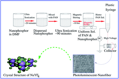 | ||
| Fig. 1 Schematic illustration of the process and fabrication of PAN/NaYF4:Eu+3 photoluminescent nanofibers (PLNs). | ||
As produced 20 mg of NaYF4:Eu+3 nanophosphor was dispersed in 4.6 g DMF. This solution was kept for the ultra-sonication upto 30 minutes at 40 °C temperature to avoid the agglomeration. After that 400 mg PAN was put into the above dispersed solution and kept it again for ultra-sonication for 90 minutes at same temperature. Further, to obtain the homogeneous PAN solution, this solution was kept under vigorous magnetic stirring for 10 h at room temperature. Two concentrations of nanophosphor, 5 and 8% were used to obtain the PLNs. Therefore, the PAN homogeneous solution was poured into the 5 ml plastic syringe having 0.7 mm diameter of needle. 13 cm × 14 cm aluminum foil sheet was used as a substrate for the PLNs which was wrapped on collector of electrospinning machine. The plastic disposal syringe was hanged at the stand of machine and the distance between the tip of syringe needle and collector was maintained at 20 cm. The applied voltages between the tip and collector were maintained at 15 kV with the flow rate of 0.15 ml h−1 and collector speed of 2000 rpm. The reagents and solvents were determined by optimizing various solutions and instrumental parameters to get the nanofibers. The concentration of phosphor material (5 and 8%) was also optimized so that solution does not get accumulate on syringe. Above 8% of NaYF4:Eu+3, it is difficult to spun nanofibers from polymer solution. Hence, random nanoscale polymeric PLNs network were obtained on aluminum foil at room temperature.
3 Result and discussion
3.1 X-ray diffraction (XRD) of PAN/NaYF4:Eu+3 nanofibers
The cubic crystal structure of NaYF4 [blue → sodium (Na), red → yttrium (Y) and green → fluorine (F)] is shown in the Fig. 2. The image was created by using Visualization for Electronic and STructure Analysis (VESTA) package.52 The ionic radius of Eu+3 (∼1.07 Å) is comparable to Y+ (∼1.159 Å) that indicates the Eu+3 can easily replace Y+ without any major change in structure.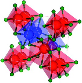 | ||
| Fig. 2 The crystal structure of NaYF4 in cubic phase (created by [blue → sodium (Na), red → yttrium (Y) and green → fluorine (F)]). | ||
The microscopic structure and crystalline nature of PAN/NaYF4:Eu+3 electrospun photoluminescent nanofibers were confirmed by XRD measurement using X-ray diffractometer Rigaku Japan with Cu-Kα radiation having a wavelength of λ = 1.5418 Å. Fig. 3(a) and (b) exhibit the XRD pattern of PAN/NaYF4:Eu+3 electrospun PLNs @ 5% and 8% concentrations of nanophosphor in PAN matrices respectively. The peak intensities are slightly higher at 8% which is the indicative of higher density of NaYF4:Eu+3 in PAN nanofibers. The diffraction peak observed at around 2θ = 16.86° which is attributed to PAN.53,54
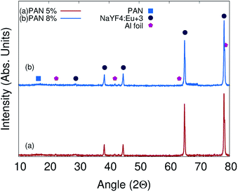 | ||
| Fig. 3 XRD pattern of PAN/NaYF4:Eu+3 electrospun PLNs @ 5% concentration of nanophosphor (a) and XRD pattern of PLNs @ 8% (b) shown. | ||
The JCPDS card no 77-2042 has been used to investigate the cubic structure of NaYF4:Eu+3 nanophosphor. The existence of peaks at angles 2θ = 28.8°, 38.42°, 43.17°, 44.72°, 65.50° and 78.72° corresponding to crystal planes (111), (200), (220), (222), (400), and (420) respectively are attributed to the nanophosphors that conforms cubic crystal structure with lattice parameters of a = b = c = 5.369 Å, α = β = γ = 90°.55 It can be seen from XRD that the peaks of composite nanophosphor are slightly right shifted which indicates a tensile stress present on NaYF4 due to the PAN molecule shell. The stress present on NaYF4 is not so efficient to deform crystal structure.56–58 The crystalline peaks centered at about angles 26.62° 42.02°, 65.12° and 78.34° are attributed to Al foil which was wrapped on collector to obtain the composite PLNs.59
3.2 Morphology of polyacrylonitrile (PAN)/NaYF4:Eu+3 PLNS
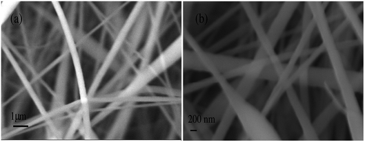
The surface morphology of ultrafine electrospun composite nanofibers was recognized by the Scanning Electron Microscope (SEM) images using model ZEISS EVO 18. Fig. 4(a and b) show the SEM images of PAN/NaYF4:Eu+3 nanophosphor composite nanofibers @ 5% and 8% respectively. The histograms for PAN/NaYF4:Eu+3 composite nanofibers are shown in Fig. 5. The diameter and pore analysis shown in the graph illustrates the size distribution of PAN/NaYF4:Eu+3 nanofibers @ 5 and 8%. In both cases, the nanofibers are semi aligned and form a network like structure. Fig. 5(a and b) shows the nanofibers embedded with 5% nanophosphor with smooth morphology and the average diameter measure as 383 nm using ImageJ analysis software. However on adding more phosphor i.e. 8% the diameter reduces due to the increase in metal content (5 to 8%) to an average size 286 nm. However, due to increased additive content more bead formation also take place in nanofibers. The average pore size of the composite nanofibers was observed ∼1351 nm and ∼453 nm @ 5 and 8% shown in Fig. 5(c and d).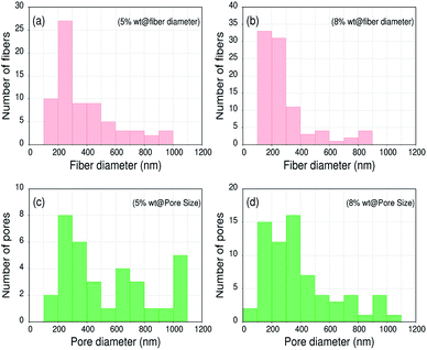 | ||
| Fig. 5 SEM image texture analysis of PAN/NaYF4:Eu+3 PLNs. (a and b) shows the fiber diameter distribution (FDD) @ 5 and 8% and (c and d) shows the pore size distribution (PSD) @ 5 and 8%. | ||
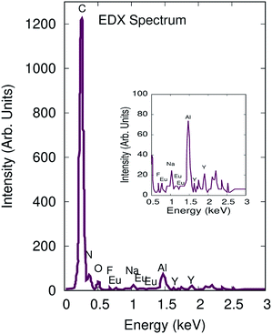
Elemental analysis was performed using the energy-dispersive spectroscopy accessory connected to the SEM system (VPSEM ZEISS EVO M-10 with OXFORD INCA EDX DETECTOR). The energy dispersive X-ray spectroscopy (EDX) spectrum is shown in Fig. 6 which revealed homogeneous distribution of all elements. The EDX spectra confirm the presence of C, N, O, Na, Y, F, Eu elements in the PAN/NaYF4:Eu+3 nanofibers. Aluminum (Al) peak is indicative of Al-foil substrate. This finding confirms that the nanofibers were fabricated efficiently with nanophosphor material. The EDX spectra show that rare earth elements (RE) are attached with the nanofibers. During the electrospinning, the polymers get stretched in the form of nanofibers along with NaYF4:Eu+3 on applying field. Hence, electrostatic interaction plays a significant role during fiber fabrication but does not play any role to activate ageing of nanofibers.
Fig. 7(a) shows the High Resolution Transmission Microscopy (HRTEM-JEOL 2100F) image of nanofibers @ 5% which exhibits the NaYF4:Eu+3 nanoparticles were homogeneously dispersed into the PAN fibers matrix. The presence of NaYF4:Eu+3 nanophosphor inside the nanofibers can be understood by the artwork image Fig. 7(b) also.
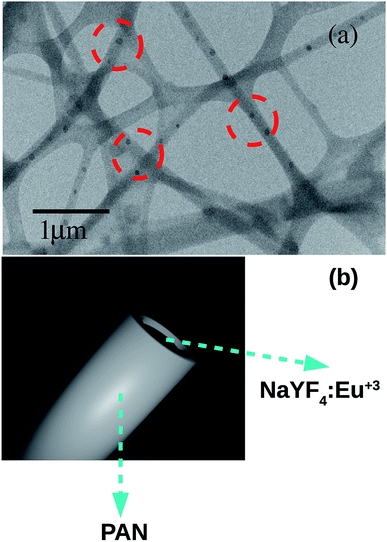 | ||
| Fig. 7 (a) HRTEM image of PLNs showing the nanoparticles of NaYF4:Eu+3 homogeneously embedded inside the nanofibers and (b) an artwork to represent NaYF4:Eu+3 crystal inside PAN nanofiber. | ||
The nano particles are well distributed into the PAN matrices due to a strong interaction between the PAN molecule chains and the Eu+3 ions. The flow rate, distance between the tip of syringe needle and collector and applied voltages are the key factors which can influence the surface morphology of composite nanofibers during the electrospinning. Flow rates of 0.2 ml h−1 and 0.3 ml h−1 have been optimized and found that many beads were present in electrospun composite nanofibers. As a result, the flow rate played an important role to get the better morphology and diameter of the resulting nanofibers. So that 0.15 ml h−1 flow rate for PAN homogeneous solution was best suited in the proposed study. One cannot ignore the importance of concentrations of nanophosphor in PAN precursor which has the considerable affect on surface morphology of the nanofibers. When the amounts of NaYF4:Eu+3 nanophosphor was increased from 0 to 8%, the ultrafine uniform and continuous PAN/NaYF4:Eu+3 electrospun composite nanofibers were achieved on collector. The needle of plastic syringe nozzle did not allow the concentrations of nanophosphor in PAN matrices beyond the 8% for smooth fabrication of nanofibers. NaYF4:Eu+3 nanophosphor has been prepared separately for the fabrication of electrospun PLNs. These nano particles were incorporated into the PAN matrix via electrospinning.
3.3 Photoluminescence properties of PAN/NaYF4:Eu+3 nanofibers
The photoluminescence spectra60–63 of bare PAN and the electrospun composite nanofibers were investigated using spectrometer model PerkinElmer LS 55 as shown in Fig. 8. NaYF4:Eu+3 nanophosphor were doped in PAN to understand the photoluminescence properties of the composite nanofibers.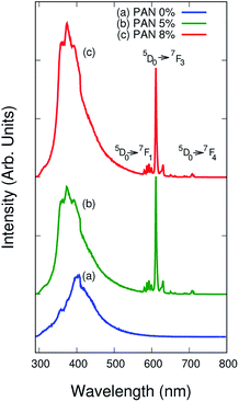 | ||
| Fig. 8 Photoluminescence spectra of (a) pure PAN, (b) PAN/NaYF4:Eu+3 PLNs @ 5% and (c) @ 8% upon excitation wavelength of 239 nm. | ||
Fig. 8(a–c) reveal the photoluminescence spectrum of pure PAN and composite nanofibers under 239 nm excitation wavelength at room temperature. The bare PAN fibers have narrow emission peak at around 405 nm whereas PAN/NaYF4:Eu+3 electrospun composite nanofibers exhibit very sharp peaks at around 593, 625, 628 and 710 nm. The characteristic sharp peaks were observed with the 5D0 → 7FJ, where J ranges from 0 to 4, transition of Eu+3 ions in the range of 300 to 710 nm region. The transition 5D0 → 7F1 at about 593 nm was observed in the orange spectral region due to the magnetic dipole transitions. While the intense sharp transitions 5D0 → 7F3 and 5D0 → 7F4 at about 625 nm and 710 nm were observed in the red spectral region of the photoluminescence spectrum due to the electric dipole transitions respectively.
The quantum efficiency (QE) is a measure of luminescence efficiency. The QE of nanofibers is calculated by eqn (1) using the integrated sphere method.64
 | (1) |
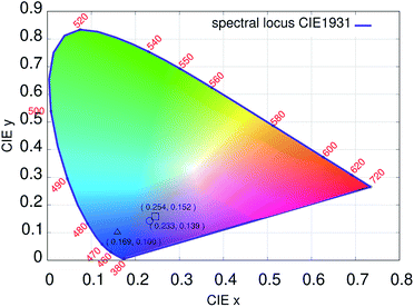
In such a case the orange peak intensity was almost negligible and hypersensitive red peaks appeared.65–67 The observations suggested that the Eu+3 ions were homogeneously impinged in the PAN matrices and placed on a molecule chain due to the effect of electric field during the electrospinning process.68 When the concentrations of NaYF4:Eu+3 nanophosphor increased up to 8%, the emission intensity increased sharply is because of Eu+3 ions get distributed homogeneously in the PAN chains. Fig. 9 shows the International Commission on Illumination (CIE) diagram from the photoluminescence spectra of electrospun nanofibers. The chromaticity diagram demonstrates the color model which is a numerical model.69 This color model represents the color spectrum visible to the ordinary man. The color space chromaticity diagram was drawn using the CIE 1931 color matching functions with the CIE coordinates (X1 = 0.169, Y1 = 0.10) @ PAN, (X2 = 0.254, Y2 = 0.152) @ 5% and (X3 = 0.233, Y3 = 0.139) @ 8% at the excitation wavelength of 239 nm. These CIE coordinates shows a variation in photoluminescence with different % concentrations.
The work has limitation that not higher content of nanophosphor material (>8% in this work) can be added due to limitation of solution flow and agglomeration on syringe's needle. In our study, smooth nanofibers with 8% of NaYF4:Eu+3 were fabricated and these are showing good photoluminescence intensity, which is sufficient for its flexible lightening application, although, more intensity will be a plus point. Novelty of the work lies in the optimization of process parameters in fabricating inorganic composite nanofibers having 8% of nanophosphor showing efficient performance of composite nanofibers. Also, no study shows the incorporation of NaYF4:Eu+3 nanophosphor in PAN polymer as nanofibers. The high effective surface of nanofibers and embedment of nanophosphor in the PAN both contributed equally in the marvelous performance of composite nanofibers.
4 Conclusion
NaYF4:Eu+3 PLNs were prepared successfully via electrospinning technique. The average diameters of PLNs were observed ∼ 310 nm. The SEM and HRTEM images clearly distinguished the existence of Eu+3 ions which are embedded homogeneously in the PAN molecule chain. The Eu+3 ions have strong coordination interaction with polymers therefore the prepared composite nanofibers exhibit the significant effect on photoluminescent properties. The composite nanofibers demonstrated the marvelous emission peaks from 593 to 710 nm region which lead the nanofibers for the stable solid state lighting applications whereas organic PAN composite nanofibers for flexible lighting applications. The results are pretty illuminating as compared to the existing studies on inorganic additives based electrospun polymeric light emitting nanofibers. After this fundamental study, there is a need to check the real time applications of the nanofibers. Future research will focus on the possible use of these nanofibers in different applications such as combating counterfeiting of expensive products, solar cell, energy storage and biomedical fields.Conflicts of interest
There are no conflicts to declare.Acknowledgements
Authors are grateful to Professor P. D. Sahare, Department of Physics and Astrophysics University of Delhi, Delhi for providing the experimental support for the preparation of nanophosphor. We would like to thank Dr Govind, Senior Principal Scientist and Mr Jai Tawale from CSIR-NPL, New Delhi for Photoluminescence (PL) and Energy Dispersive X-ray Spectroscopy (EDX) characterization respectively. Also, we thank to Professor Beer Pal Singh (Head), and Dr Yogendra Kumar Gautam, Department of Physics, C. C. S. University, Meerut, UP for providing facilities of SEM. One of the authors, Dr Ashish Gupta thanks CSIR for RA.Notes and references
- Q. Zhang, Q. Du, Y. Zhao, F. Chen, Z. Wang, Y. Zhang, H. Ni, H. Deng, Y. Li and Y. Chen, RSC Adv., 2017, 7, 28826–28836 RSC.
- H. Dai, E. W. Wong, Y. Z. Lu and C. M. Lieber, Nature, 1995, 375, 769–772 CrossRef CAS.
- P. D. Yang and C. M. Lieber, Science, 1996, 273, 1836 CrossRef CAS.
- C. Nacci, F. Ample, D. Bleger, S. Hecht, C. Joachim and L. Grill, Nat. Commun., 2015, 6, 7397 CrossRef PubMed.
- W. R. Stauffer and X. T. Cui, Biomaterials, 2004, 25, 2477–2488 CrossRef PubMed.
- Y. J. Chen, J. B. Li, Y. S. Han, X. Z. Yang and J. H. Dai, J. Cryst. Growth, 2002, 245, 163–170 CrossRef CAS.
- J. Liu, Z. Yang, B. Ye, Z. Zhao, Y. Ruan, T. Guo, X. Yu, G. Chen and S. Xu, J. Mater. Chem. C, 2019, 7, 4934–4955 RSC.
- M. A. Sobhan, A. Lebedev, L. L. Chng and F. Anariba, J. Nanomater., 2018, 1980357 CAS.
- M. Yang, J. Yu, S. Jiang, C. Zhang, Q. Sun, M. Wang, H. Zhou, C. Li, B. Man and F. Lei, Opt. Express, 2018, 26, 20649–20660 CrossRef CAS PubMed.
- S. G. Itankar, M. P. Dandekar, S. B. Kondawar and B. M. Bahirwar, Luminescence, 2017, 32, 1535–1540 CrossRef CAS PubMed.
- M. M. A. Abualrejal, H. Zou, J. Chen, Y. Song and Y. Sheng, Adv. Nanopart., 2017, 6, 33–47 CrossRef CAS.
- J. Y. Lei, W. Wang, M. X. Song, B. Dong, Z. Y. Li and C. Wang, React. Funct. Polym., 2011, 71, 1071–1076 CrossRef CAS.
- R. Tatavarty, E. T. Hwang, J. W. Park and J. H. Kwak, React. Funct. Polym., 2011, 71, 104–108 CrossRef CAS.
- D. R. Son, A. V. Raghu, K. R. Reddy and H. M. Jeong, J. Macromol. Sci., Part B: Phys., 2016, 55, 1099–1110 CrossRef CAS.
- K. Reddy, K. Karthik, S. B. Prasad, S. Soni, H. Jeong and A. Raghu, Polyhedron, 2016, 120, 169–174 CrossRef CAS.
- K. R. Reddy, K. P. Lee and A. I. Gopalan, J. Nanosci. Nanotechnol., 2007, 7, 3117–3125 CrossRef CAS PubMed.
- K. R. Reddy, B. C. Sin, K. S. Ryu, J. C. Kim, H. Chung and Y. Lee, Synth. Met., 2009, 159, 595–603 CrossRef CAS.
- S. J. Han, H. I. Lee, H. M. Jeong, B. K. Kim, A. V. Raghu and K. R. Reddy, J. Macromol. Sci., Part B: Phys., 2014, 53, 1193–1204 CrossRef CAS.
- K. R. Reddy, K. P. Lee and A. I. Gopalan, J. Appl. Polym. Sci., 2007, 106, 1181–1191 CrossRef CAS.
- M. Hassan, K. R. Reddy, E. Haque, S. N. Faisal, S. Ghasemi, A. I. Minett and V. G. Gomes, Compos. Sci. Technol., 2014, 98, 1–8 CrossRef CAS.
- K. R. Reddy, K. P. Lee, Y. Lee and A. I. Gopalan, Mater. Lett., 2008, 62, 1815–1818 CrossRef CAS.
- Y. R. Lee, S. C. Kim, H. Lee, H. M. Jeong, A. V. Raghu, K. R. Reddy and B. K. Kim, Macromol. Res., 2011, 19, 66–71 CrossRef CAS.
- M. U. Khan, K. R. Reddy, T. Snguanwongchai, E. Haque and V. G. Gomes, Colloid Polym. Sci., 2016, 294, 1599–1610 CrossRef CAS.
- S. H. Choi, D. H. Kim, A. V. Raghu, K. R. Reddy, H. I. Lee, K. S. Yoon, H. M. Jeong and B. Kyu Kim, J. Macromol. Sci., Part B: Phys., 2012, 51, 197–207 CrossRef CAS.
- M. L. Shofner, F. J. Rodriguez-Macias and R. Vaidyanathan, Composites, 2003, 34, A1207 CrossRef.
- C. J. Otten, O. R. Louire, M. F. Yu, J. M. Cowley, M. J. Dyer, R. S. Ruoff and W. E. Buhro, J. Am. Chem. Soc., 2002, 124, 4564–4565 CrossRef CAS PubMed.
- R. Stepanyan, A. Subbotin, L. Cuperus, P. Boonen, M. Dorschu, F. Oosterlinck and M. Bulters, Appl. Phys. Lett., 2014, 105, 173105–173109 CrossRef.
- D. H. Reneker, A. L. Yarin, H. Fong and S. Koombhongse, J. Appl. Phys., 2000, 87, 4531–4547 CrossRef CAS.
- A. Formhals, US Pat., 1975504, 1934.
- L. M. Larrondo and R. S. J. Manley, J. Polym. Sci., Polym. Phys. Ed., 1981, 12, 921–932 CrossRef.
- P. Khude, J. Mater. Sci. Eng., 2017, 6, 1000399 Search PubMed.
- Y. Liu, R. Liu, X. Wang, J. Jiang, W. Li, J. Liu, S. Guo and G. Zheng, Micromachines, 2018, 9, 427 CrossRef PubMed.
- G. Y. Adachi and N. Imanaka, Chem. Rev., 1998, 98, 1479–1514 CrossRef CAS PubMed.
- B. C. Hong and K. Kawano, Sol. Energy Mater. Sol. Cells, 2003, 80, 417–432 CrossRef CAS.
- Z. Yu, L. Shen, D. Li, E. Y. B. Pun, X. Zhao and H. Lin, Sci. Rep., 2020, 10, 926 CrossRef CAS PubMed.
- B. Safaei, M. Youssefi, B. Rezaei and N. Irannejad, Smart Science, 2017, 6, 117–124 CrossRef.
- H. G. Liu, F. Xiao, W. S. Zhang and Y. Chung, J. Lumin., 2005, 114, 187–196 CrossRef CAS.
- H. Liu, Y. Lee, W. P. Qin, K. Jang and X. S. Feng, Mater. Lett., 2004, 58, 1677–1682 CrossRef CAS.
- F. Wang, Y. Han, C. S. Lim, Y. Lu, J. Wang, J. Xu, H. Chen, C. Zhang, M. Hong and X. Liu, Nature, 2010, 463, 1061–1065 CrossRef CAS PubMed.
- O. Graeve, S. Varma, G. George, D. Brown and E. Lopez, J. Am. Chem. Soc., 2006, 89, 926–931 CAS.
- C. Li, C. Zhang, Z. Hou, L. Wang, Z. Quan, H. Lian and J. Lin, J. Phys. Chem. C, 2009, 113, 2332–2339 CrossRef CAS.
- K. Kramer, D. Biner, G. Frei, H. Güdel, M. Hehlen and S. Lüthi, Chem. Mater., 2004, 16, 1244–1251 CrossRef.
- E. Zussman, X. Chen, W. Ding, L. Calabri, D. A. Dikin, J. P. Quintana and R. S. Ruoff, Carbon, 2005, 43, 2175–2185 CrossRef CAS.
- V. E. Kalayci, P. K. Patra, Y. K. Kim, S. C. Ugbolue and S. B. Warner, Polymer, 2005, 46, 7191–7200 CrossRef CAS.
- K. Yoon, K. Kim, X. Wang, D. Fang, B. S. Hsiao and B. Chu, Polymer, 2006, 47, 2434–2441 CrossRef CAS.
- Y. Wang, L. Huang, J. Tang, Y. Wang, X. Li and W. Ma, Int. J. Electrochem. Sci., 2016, 11, 2058–2065 CAS.
- H. Wang, Q. Yang, L. Sun, C. Zhang, Y. Li, S. Wang and Y. Li, J. Alloys Compd., 2009, 488, 414–419 CrossRef CAS.
- Y. Zhou, L. Y. Hao, Y. Hu, R. Y. Zhu and Z. K. Chen, Chem. Lett., 2000, 1308–1309 CrossRef CAS.
- A. Gole and C. J. Murphy, Chem. Mater., 2005, 17, 1325–1330 CrossRef CAS.
- C. Wang, E. Yan, Z. Y. Sun, Z. J. Jiang, Y. B. Tong, Y. Xin and Z. H. Huang, Macromol. Mater. Eng., 2007, 292, 949–1008 CrossRef CAS.
- S. Kumar, G. Jain, B. P. Singh and S. R. Dhakate, J. Nanomater., 2020, 1023589 Search PubMed.
- K. Momma and F. Izumi, J. Appl. Crystallogr., 2011, 44, 1272–1276 CrossRef CAS.
- M. Panapoy, A. Dankeaw and B. Ksapabutr, Thammasat Int. J. Sci. Tech., 2008, 13, 11–17 Search PubMed.
- P. S. Saud, Z. K. Ghouri, B. Pant, T. An, J. H. Lee, M. Park and H. Y. Kim, Carbon Lett., 2016, 18, 30–36 CrossRef.
- A. K. Gangwar, A. Gupta, G. Kedawat, P. Kumar, B. P. Singh, N. Singh, A. K. Srivastava, S. R. Dhakate and B. K. Gupta, Chem.–Eur. J., 2018, 24, 9477–9484 CrossRef CAS PubMed.
- K. Kumar, P. Arun, C. R. Kant and B. K. Juluri, Appl. Phys. Lett., 2012, 100, 243106 CrossRef.
- K. Kumar, P. Arun, C. R. Kant, N. C. Mehra and V. Mathew, Appl. Phys. A, 2010, 99, 305–310 CrossRef CAS.
- K. Kumar, P. Arun, C. R. Kant, N. C. Mehra, L. Makinistian and E. A. Albanesi, J. Phys. Chem. Solids, 2010, 71, 163–169 CrossRef CAS.
- M. Manikandan, J. Gopal and S. Chun, RSC Adv., 2016, 6, 32405–32413 RSC.
- M. Hassan, E. Haque, K. R. Reddy, A. I. Minett, J. Chenc and V. G. Gomes, Nanoscale, 2014, 6, 11988–11994 RSC.
- M. J. Kade, D. J. Burke and C. J. Hawker, J. Polym. Sci., Part A: Polym. Chem., 2010, 48, 1477–1484 CrossRef.
- K. R. Reddy, K. P. Lee, J. Y. Kim and Y. Lee, J. Nanosci. Nanotechnol., 2008, 8, 5632–5639 CrossRef CAS PubMed.
- N. L. Reddy, V. N. Rao, M. V. kumar, R. Santhosh, S. Anandan, M. Karthik, M. V. Shankar, K. R. Reddy, N. P. Shetti, M. N. Nadagoudae and T. M. Aminabhavi, Int. J. Hydrogen Energy, 2019, 44, 10453–10472 CrossRef CAS.
- S. Miao, Z. Xia, J. Zhang and Q. Liu, Inorg. Chem., 2014, 53, 10386–10393 CrossRef CAS PubMed.
- R. He, X. F. Qian, J. Yin, L. J. Bian, H. A. Xi and Z. K. Zhu, Mater. Lett., 2003, 57, 1351–1354 CrossRef CAS.
- Q. Li, T. Li and J. Wu, J. Phys. Chem. B, 2001, 105, 12293–12296 CrossRef CAS.
- A. Tiwari, A. K. Mishra, H. Kobayanshi and A. P. F. Turner, Contemp. Phys., 2013, 54, 74 Search PubMed.
- J. Kalinowskia, W. Stampor, M. Cocchi, D. Virgili and V. Fattori, J. Appl. Phys., 2006, 100, 034318 CrossRef.
- A. M. Ortega, M. T. Lopez, F. C. Garcia, J. A. Reglero, M. M. Alonso, G. Espino and J. M. Garcia, Eur. Polym. J., 2017, 95, 119–126 CrossRef.
| This journal is © The Royal Society of Chemistry 2020 |

