
 Open Access Article
 This Open Access Article is licensed under a Creative Commons Attribution-Non Commercial 3.0 Unported Licence
MoO2 nanoparticles embedded in N-doped hydrangea-like carbon as a sulfur host for high-performance lithium–sulfur batteries†
Yasai Wanga,
Guilin Fengb,
Yang Wanga,
Zhenguo Wu a,
Yanxiao Chen*a,
Xiaodong Guoa and
Benhe Zhonga
a,
Yanxiao Chen*a,
Xiaodong Guoa and
Benhe Zhonga
aSchool of Chemical Engineering, Sichuan University, Chengdu 610065, China. E-mail: yxchen888@163.com; Fax: +86-28-85406702; Tel: +86-28-85406702
bRIES, Hokkaido University, N20W10, Kita-Ward, Sapporo 001-0020, Japan
First published on 27th May 2020
Abstract
Lithium–sulfur batteries are considered to be promising energy storage devices owing to their high energy density, relatively low price and abundant resources. However, the low utilization of insulated active materials and shuttle effect have severely hindered the further development of lithium–sulfur batteries. Herein, MoO2 nanoparticles embedded in N-doped hydrangea-like carbon have been synthesized by liquid-phase reaction followed by an annealing process and used as a sulfur host. The nitrogen-doped carbon matrix improves electrical conductivity and provides pathways for smooth electron and Li ion transfer to uniformly dispersed sulfur. Meanwhile, MoO2 nanoparticles can absorb polysulfide ions by forming strong chemical bonds, which can effectively alleviate the polysulfide shuttling effect. These results showed a good rate performance: 1361, 1071, 925, 815 and 782 mA h g−1 at the current densities of 0.1, 0.2, 0.5, 1 and 2 A g−1, and capacity retention of 85% after 300 cycles at 1 A g−1. The excellent performance was due to the synergistic effects of the polar MoO2 and nitrogen-doped carbon matrix, which can effectively restrain and reutilize active materials by absorbing polysulfides and catalyzing the transformation of polysulfides.
Introduction
In order to alleviate the deterioration caused by environmental pollution and satisfy the need for portable electronic devices and electric vehicles (EVs), it is extremely urgent to research a battery system with high energy density. Lithium–sulfur batteries (LSBs) have gained increasing attention as a promising storage system for next-generation batteries, due to their high theoretical specific capacity of 1675 mA h g−1 and high energy density of about 2600 W h kg−1.1–5 Meanwhile, elemental sulfur used as the active cathode material of LSBs is naturally abundant, low cost, non-toxic and environment-friendly.6,7 Although lithium–sulfur batteries manifest extremely obvious advantages over other secondary batteries, there are still many challenges impeding their practical large-scale application: sulfur and the discharge products Li2S2/LiS2 are both electrical insulators; the intermediate lithium polysulfides (LiPSs) produced in the reaction process are easily soluble in the ether-based electrolyte, resulting in the sluggish redox kinetics and the notorious “shuttle effect”; the process of charge–discharge conversion is accompanied with huge volume change of almost 80%.8–10 Finally, these problems lead to the low utilization of active materials, fast capacity degradation, poor cycle life and undesirable coulombic efficiency.11In recent years, researchers have designed various materials to improve the performance of the lithium–sulfur batteries. Carbon-based materials are considered as the most feasible sulfur host materials because of their relatively excellent electrochemical conductivity and structural stability.12,13 In addition, carbon materials with a large specific surface area and plentiful porosity could block LiPSs in the cathode region through physical adsorption, reducing the loss of active material.14 Carbonaceous materials were widely used as sulfur host materials, such as porous carbon,15 carbon nanotubes,16 graphene17,18 and conductive polymers19 exhibit better cycling performance than pure sulfur electrodes. It is widely accepted that the performance of lithium–sulfur battery can be enhanced by non-polar adsorption of carbon materials during the short stage. However, physical encapsulation isn't effective to restrain the shuttle effect due to the nonpolar surface. Furthermore, heteroatom-doped carbon materials especially N doped carbon were verified to show better ability to promote the performance of lithium–sulfur batteries on account of the enhanced electrical conductivity and the increased affinity for soluble polysulfides.20 Some polar metal materials have been investigated that they could immobilize the LiPSs and improve the reaction kinetics by forming strong chemical bonds with polar polysulfides. For instance, MnO2,21 Co3O4,22 TiO2,23 MoO3,24 NiCo2O4,25 and ZnS26 were verified to alleviate the shuttle effect by accelerating the conversion of LiPSs. However, most metal oxides suffer from the low electrical conductivity, which affects redox kinetics to a certain degree.27 Therefore, more efficient polysulfide-trapping strategies to meet the needs of lithium–sulfur batteries are to employ the synergistic effects of high conductivity of carbon materials and chemical adsorption of metal oxides.
In this work, we synthesized a highly conductive MoO2 nanoparticles embedded in nitrogen-doped carbon microflowers as sulfur host. In the preparation, ammonium tetrahydrate was used as the molybdenum source, dopamine as the inherent nitrogen-containing carbon precursor. The catechol functional groups of dopamine can adsorb and chelate molybdate ions, and meanwhile dopamine can spontaneously polymerize under alkaline conditions to form hydrangea-like shape Mo-dopamine compound.28 Subsequently, the obtained Mo-dopamine compound was calcined at 700 °C to form the final MoO2 nanoparticles embedded in N-doped hydrangea-like carbon (MHC). The MHC composite manifests several obvious advantages: (1) the carbon framework provides a conductive structure that greatly promotes the charge transfer and accelerates the reaction kinetics; (2) the MoO2 nanoparticles can effectively restrain LiPSs by forming chemical bonds and promote the conversion of lithium polysulfides; (3) the hydrangea-like structure is beneficial to increase specific surface area and improve the dispersion of active material. Based on the above advantages, the MoO2 embedded in carbon matrix composite shows enhanced cyclic stability, which deliver a capacity retention of 85% after 300 cycles at 1 A g−1.
Experimental section
Synthesis of MHC and MHC/S composites
The MoO2 nanoparticles embedded in N-doped hydrangea-like carbon matrix (MHC) was fabricated by liquid phase reaction accompanied by the progress of high temperature treatment, according to the previous literature.28 All the raw materials were used without further purification. Firstly, 640 mg of ammonium tetrahydrate (NH4)6Mo7O24·4H2O was dissolved in 20 mL deionized water and 10 mL ethanol under vigorous stirring for 30 min to obtain a clear solution. Then the pH value of the solution was adjusted to 8.5 by adding ammonia water. After stirring for 10 min, 15 mL of 20 mg mL−1 dopamine hydrochloride was dropped into the above solution, forming orange-red solution. After stirring for 12 h at room temperature, the solid powder was obtained by centrifuging and washing with deionized water and ethanol for several times and then freezing dried. Finally, the dried solid sample was carbonized at 700 °C for 3 h under argon gas flow with the heating rate of 5 °C min−1, named MHC-1. MHC-2 and MHC-3 compounds were prepared by being carbonized at 700 °C for 4 h and 5 h respectively.The MHC/S compound was obtained by a typical melting-diffusion method. The MHC powder and sublimed sulfur were ball milled together uniformly in a mass ratio of 1/3 for 30 min and afterward the mixture was transferred to a tube furnace and heated at 155 °C for 12 h under Ar atmosphere. By contrast, another material AB/S made from the composite of acetylene black and sulfur was prepared through the same procedure.
Battery assembly
The cathode material was prepared by mixing active material (MHC/S or AB/S), Ketjenblack and polyvinylidene fluoride (PVDF) in the weight ratio of 7![[thin space (1/6-em)]](https://www.rsc.org/images/entities/char_2009.gif) :2:1 with N-methyl-e-pyrrolidinone (NMP) as the dispersant to obtain homogeneous slurry. The slurry was casted onto aluminum foil with doctor blade and then dried at 60 °C for 12 h in the vacuum oven. The obtained piece was punched into circular disks with a diameter of 14 mm as a cathode film. CR2025 coin cells were assembled in an argon-filled glove box, in which both the O2 and H2O contents were controlled to be less than 0.1 ppm. Celgard2400 polypropylene membrane and Li foil were used as the separator and anode respectively. Besides, the electrolyte was 1.0 M bis(trifluoromethanesulfonyl)imide (LiTFSI) lithium in a mixed solvent of 1,2-dimethoxyethane (DME) and 1,3-dioxolane (DOL) (v/v, 1:1) with 0.1 M LiNO3. The loading mass of sulfur in the cathode was about 1 mg cm−2.
:2:1 with N-methyl-e-pyrrolidinone (NMP) as the dispersant to obtain homogeneous slurry. The slurry was casted onto aluminum foil with doctor blade and then dried at 60 °C for 12 h in the vacuum oven. The obtained piece was punched into circular disks with a diameter of 14 mm as a cathode film. CR2025 coin cells were assembled in an argon-filled glove box, in which both the O2 and H2O contents were controlled to be less than 0.1 ppm. Celgard2400 polypropylene membrane and Li foil were used as the separator and anode respectively. Besides, the electrolyte was 1.0 M bis(trifluoromethanesulfonyl)imide (LiTFSI) lithium in a mixed solvent of 1,2-dimethoxyethane (DME) and 1,3-dioxolane (DOL) (v/v, 1:1) with 0.1 M LiNO3. The loading mass of sulfur in the cathode was about 1 mg cm−2.
Characterization and electrochemical measurement
Crystalline phase of the as-prepared samples was determined by powder X-ray diffraction (XRD, PANalytical EMPYREAN) in the 2θ range of 10–80° using Cu Kα radiation. The morphologies were characterized by scanning electron microscopy (SEM, FEI Inspect F50) and transmission electron microscopy (TEM, FEI HELIOS NanoLab 600i). X-ray photoelectron spectroscopy (XPS, PHI Quantera II ESCA System) was performed to analyze the valence state of the element. The specific surface area and N2 adsorption/desorption isotherms were carried out from a surface area and pore size analyzer (Quantachrome Instruments) at 77 K. Thermogrametric analysis (TGA, TA Instruments, Q600) was measured to analyze the sulfur content in the compound. Phase analyses of carbon were measured by Raman spectroscopy (Bio-Rad FTS6000).The electrochemical performances of the assembled half cells were measured using a Neware BTS-610 battery tester in the potential window of 1.7–2.8 V (vs. Li/Li+). The cycle voltammetry (CV) test were conducted on an electrochemical workstation (CHI660E) between 1.7 V and 2.8 V at a scan rate of 0.1 mV s−1. The electrochemical impedance spectroscopy (EIS) was acquired using the electrochemical workstation (Germany, ZenniumIM6). All electrochemical measures were done at room temperature.
Visualized adsorption test
A 10 mmol L−1 Li2S6 solution was prepared by adding Li2S and elemental sulfur at a stoichiometric ratio of 1:5 in DME/DOL (1:1 by volume) solvent followed by magnetic stirring at 60 °C to form a uniform solution. 10 mg of MHC was added into 5 mL solution and rested for times to observe the color change of the solution.
Results and discussion
The XRD patterns in Fig. 1a demonstrate the phase structure and crystallinity of the obtained samples. The diffraction peaks of all the samples could be verified to the monoclinic MoO2 phase according to JCPDS no. 32-0671. The diffraction peaks at 26.0°, 37.0° and 53.5° were assigned to the (−111), (−211) and (−312) planes of monoclinic MoO2. The significant broad diffraction peaks indicate the nanoscale of MoO2 particles owing to being defined in the carbon matrix.29,30 The diffraction peak of carbon frame is not obvious because of the strong peak of MoO2 at 26°.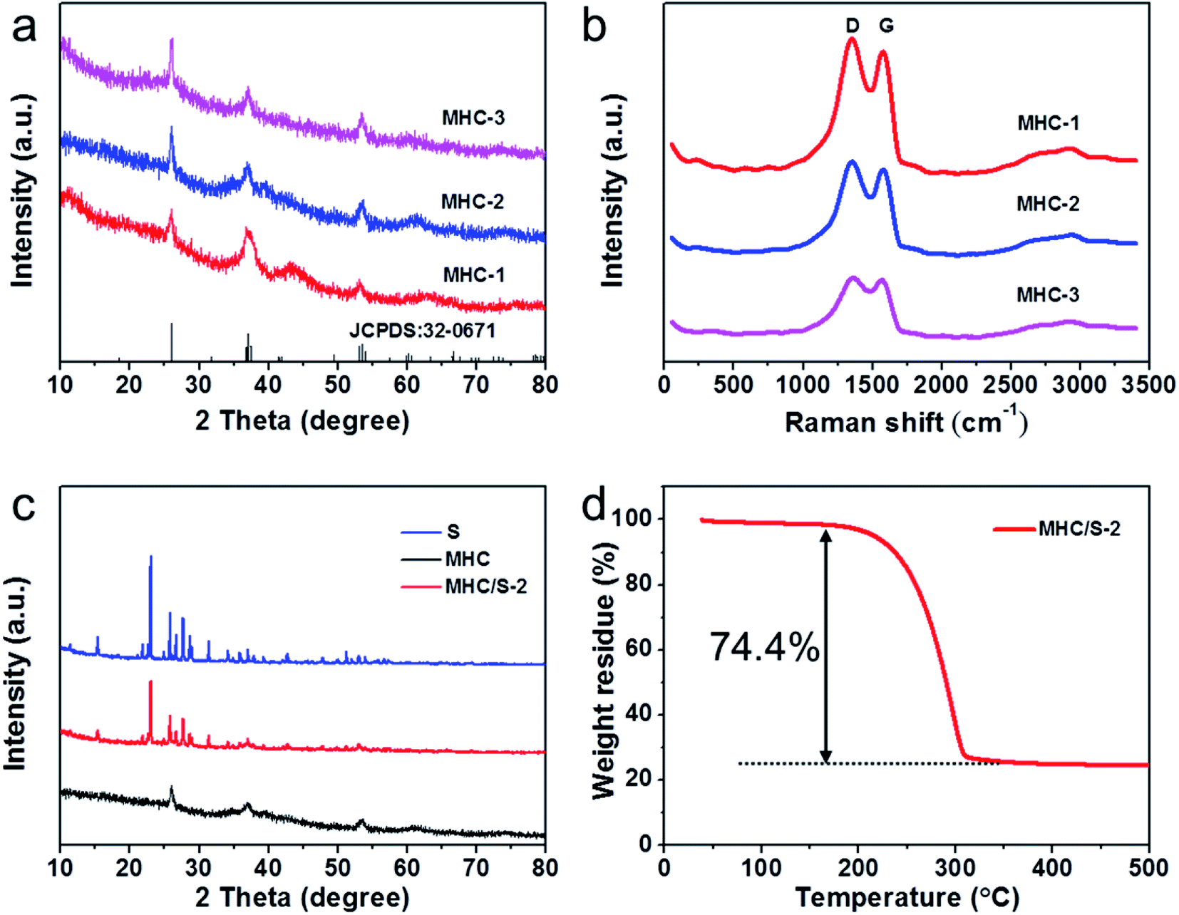 | ||
| Fig. 1 (a) XRD patterns of MHCs at the different calcination time; (b) Raman spectrum of MHCs at the different calcination time; (c) XRD patterns of MHC/S-2, S and MHC; (d) TGA curve of MHC/S-2 composite under argon atmosphere. | ||
In order to further characterize the carbon matrix in the samples, Raman test was conducted. As shown in Fig. 1b, two prominent peaks located at 1350 cm−1 (D band, the breathing vibration of the hybrid carbon rings) and 1580 cm−1 (G band, the stretching vibration of sp2 carbon atom pairs) could be observed in all samples, which manifest the existence of carbon matrix.31,32 The high intensity ratio of D band to G band (1.11 for MHC-1, 1.09 for MHC-2, 1.03 for MHC-3) reveals the rich defects in carbon matrix, which may contribute to the element doping.15 Moreover, the broader and weaker bump peak around 2800 cm−1 (2D band) indicates the multilayer structure of carbon structures.33 Both the XRD and Raman spectrum reveal that MHCs were successfully prepared. A typical melt-diffusion approach was adopted to prepare the MHC/Ss compound. And the XRD patterns of sublimated sulfur and MHC/S-2 are shown in Fig. 1c. The existence of evident orthorhombic sulfur peaks can be observed in MHC/S-2 compound and its peak intensity is weaker compared to the sublimed sulfur sample, which indicates that the crystalline size of sulfur decreases to nanoscales due to being encapsulated into the carbon matrix.34 The sulfur content of MHC/S-2 was shown in Fig. 1d. It could be seen that the mass loss mainly occurs during 200–300 °C, mainly due to the sublimation of sulfur, showing the sulfur mass percentage was 74.4%.
The morphologies of MHC compounds at different calcination times are characterized by scanning electron microscopy (SEM). As shown in Fig. 2a–c, the MHC compounds have 3D hydrangea-like architecture. The microflower is assembled with many flakes from inside to outsides, with an average thickness of 30 nm. Such feature is beneficial to increase specific surface area and the uniform dispersion of S and Li2S, leading to good electrical contact. And the MHC compounds in hydrangea-like structure can facilitate the penetration of electrolyte and facile transportation of Li+, which can improve the electrochemical reaction kinetics. And it can be found that the microflowers become more compacted with thin flakes stacking more tightly with the increase of calcination time. Furthermore, numerous dark nanoparticles with a small size of 30–50 nm are detected to distribute in the carbon frame by transmission electron microscopy (TEM), as presented in Fig. 2d and e. The high-resolution TEM (HRTEM) image in Fig. 2f further reveals the lattice fringes with a distance of 0.342 nm is corresponding to the (![[1 with combining macron]](https://www.rsc.org/images/entities/char_0031_0304.gif) 11) planes of MoO2. SAED analysis (inset of Fig. 2f) again verified the crystalline phase of MoO2 and the interlattice spacing of 0.183 nm and 0.127 nm corresponding to the (
11) planes of MoO2. SAED analysis (inset of Fig. 2f) again verified the crystalline phase of MoO2 and the interlattice spacing of 0.183 nm and 0.127 nm corresponding to the (![[3 with combining macron]](https://www.rsc.org/images/entities/char_0033_0304.gif) 01) plane and the (14) plane of MoO2 (JCPDS no. 32-0671), which was in accordance with the XRD and HRTEM result.30 In addition, the high-angle annular dark field scanning transmission electron microscopy and the corresponding element mappings in Fig. 2g and h demonstrate that Mo, O, C and N element are homogeneously dispersed in the MHC. The nitrogen substance comes from the nitrogen-containing amine functionality of dopamine molecules.
01) plane and the (14) plane of MoO2 (JCPDS no. 32-0671), which was in accordance with the XRD and HRTEM result.30 In addition, the high-angle annular dark field scanning transmission electron microscopy and the corresponding element mappings in Fig. 2g and h demonstrate that Mo, O, C and N element are homogeneously dispersed in the MHC. The nitrogen substance comes from the nitrogen-containing amine functionality of dopamine molecules.
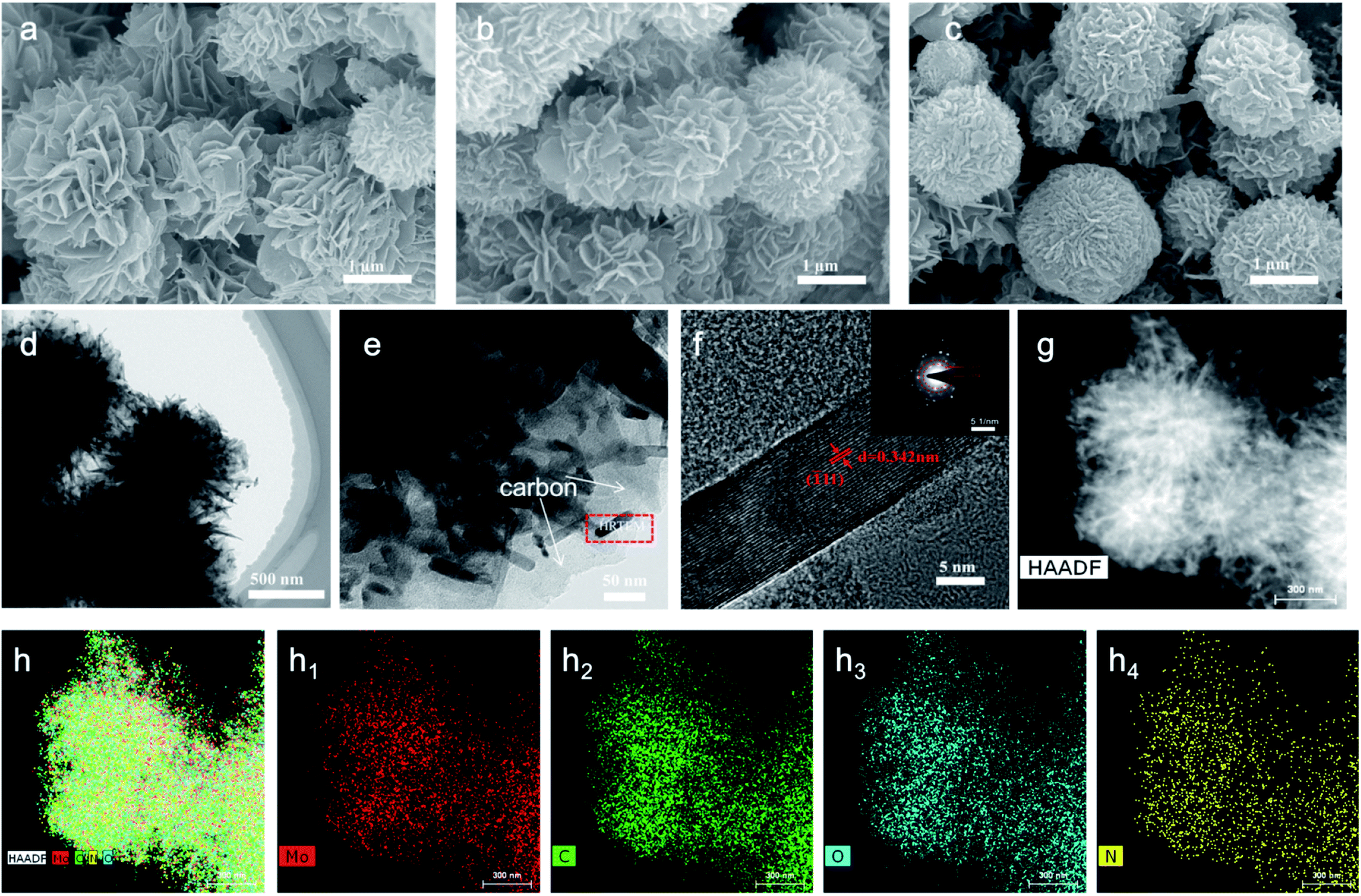 | ||
| Fig. 2 (a–c) SEM images of MHC-1, 2 and 3; (d and e) TEM images of MHC-2; (f) HRTEM image of MHC-2 (inset of selected area electron diffraction image); (g) HAADF-STEM image and (h) the corresponding element mappings of Mo (h1), C (h2), O (h3) and N (h4). | ||
The N2 adsorption/desorption isotherms of MHCs are presented in Fig. 3a–c. The representative type IV isotherms of three samples indicate the abundance in micropores and mesopores.35 The prepared MHC-1, MHC-2 and MHC-3 exhibit a specific surface area of 172.8 m2 g−1, 118.8 m2 g−1 and 99.3 m2 g−1, respectively. The MHC-2 and MHC-3 delivered smaller specific area, attributing to the closer stacking of lamellas of microflowers. Based on density functional theory (DFT) analysis, the pore-size distributions in the inset of Fig. 3a–c indicate that MHCs have hierarchical porosity at 2 nm to 10 nm. The hierarchical micro–meso pores are considered to help mitigate the diffusion of polysulfide by the physical adsorption. The large specific surface area may be attributed to the formation of hierarchical structure during the interaction progress of Mo between dopamine hydrochloride, which is beneficial for the even dispersion of sulfur and a better wettability of the electrolyte.37 The morphology of MHC/S-2 compound was exhibited in Fig. 3d to show that sulfur is evenly dispersed in the MHC-2 without apparent aggregation.
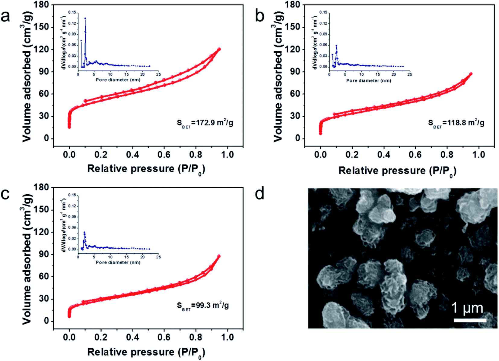 | ||
| Fig. 3 N2 adsorption–desorption isotherms results of (a) MHC-1; (b) MHC-2; (c) MHC-3 (inset: pore-size distributions); (d) SEM of MHC/S-2 compound. | ||
X-ray photoelectron spectroscopy (XPS) was conducted to analyze the valences and chemical bonding states of MHC-2 and the results were exhibited in Fig. 4. As shown in Fig. S1,† the full survey spectrum revealed the presence of Mo, O, C and N, in accordance with the EDS results. The Mo 3d high-resolution spectra in Fig. 4a can be deconvoluted into two doublets. The doublets at 230.1 and 232.8 eV are assigned to Mo 3d5/2 and Mo 3d3/2 of Mo4+, respectively. The doublets at 232.2 and 235.9 eV are corresponding to Mo 3d5/2 and Mo 3d3/2 of Mo6+.36–38 The observation of Mo6+ in the Mo 3d spectra of MoO2 was reported in the previous literature, which may be derived from the slight surface oxidation of metastable MoO2 by air.39 The spectrum of C 1s in Fig. 4b can be fitted into four peaks at 284.5, 285.2, 286.6 and 288.9 eV, which can be indexed to C–C, C–O–Mo, C–O–C and C![[double bond, length as m-dash]](https://www.rsc.org/images/entities/char_e001.gif) O binding energies, respectively. The peaks with binding energies of 533.4, 531.8 and 530.4 eV in O 1s spectrum in Fig. 4c can be ascribed to the CO, C–O–C and Mo–O bonding energies. This suggests that the obtained material contains oxygen-containing functional groups on the surface, which was believed to improve the binding interaction to LPSs.38 The N-doping was further confirmed by the N 1s spectra in Fig. 4d. The peaks at 401.5 and 398.2 eV correspond well to quaternary-type N and pyridinic N doped in the carbon matrix.40 In addition, the nitrogen-doping in the carbon have been proved to improve the electrical conductivity of carbon and the affinity of soluble polysulfides.41
O binding energies, respectively. The peaks with binding energies of 533.4, 531.8 and 530.4 eV in O 1s spectrum in Fig. 4c can be ascribed to the CO, C–O–C and Mo–O bonding energies. This suggests that the obtained material contains oxygen-containing functional groups on the surface, which was believed to improve the binding interaction to LPSs.38 The N-doping was further confirmed by the N 1s spectra in Fig. 4d. The peaks at 401.5 and 398.2 eV correspond well to quaternary-type N and pyridinic N doped in the carbon matrix.40 In addition, the nitrogen-doping in the carbon have been proved to improve the electrical conductivity of carbon and the affinity of soluble polysulfides.41
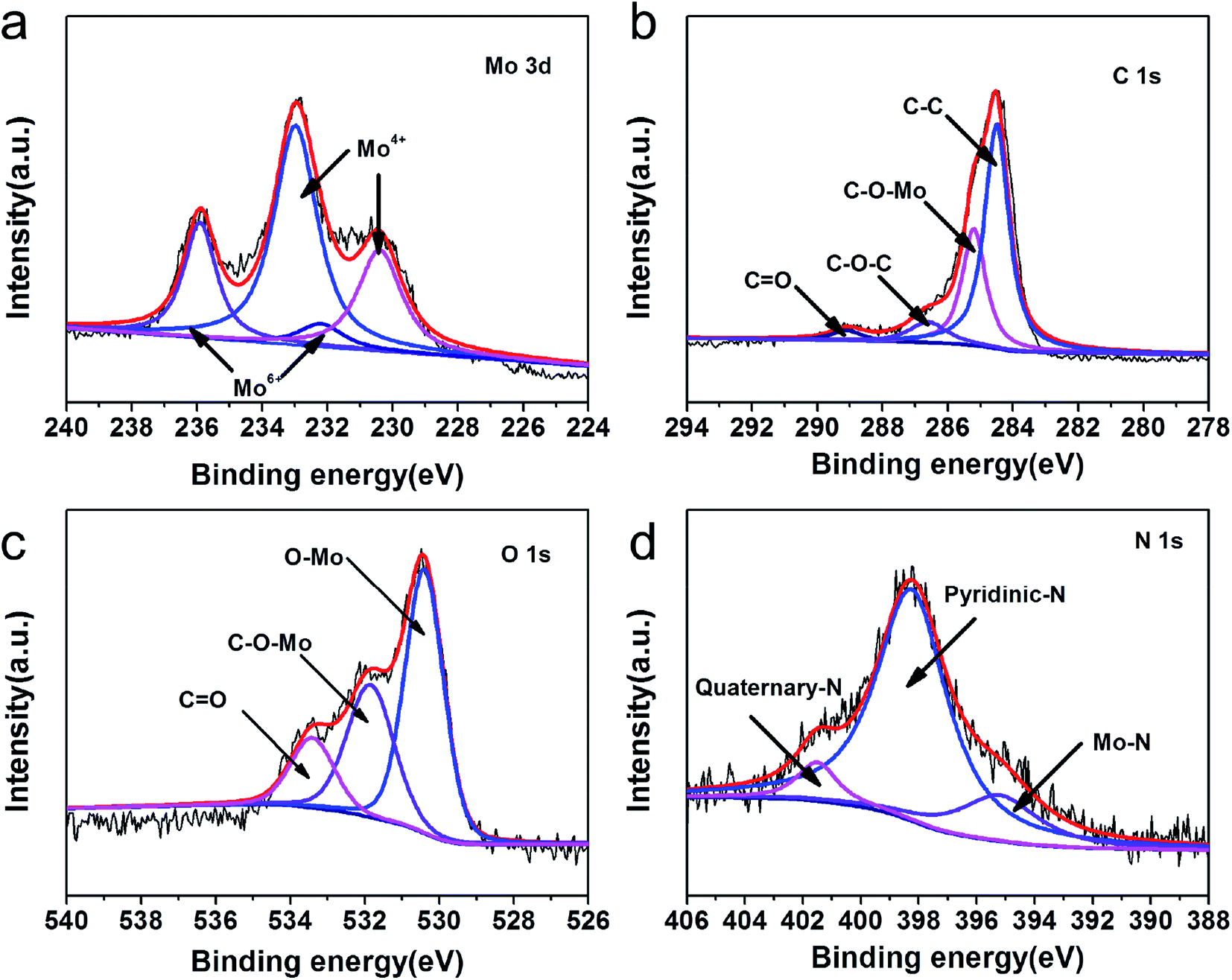 | ||
| Fig. 4 High-resolution XPS spectra of MHC-2: (a) Mo 3d; (b) C 1s; (c) O 1s; (d) N 1s. | ||
2025 coin cells were assembled to test the electrochemical performance, and all the discharge capacities in this study were calculated on the basis of the mass of pure elemental sulfur. Fig. 5a reveals the rate performances of different cells at current densities from 0.1 to 0.2, 0.5, 1.0 and 2.0 A g−1. The MHC/S-2 cell delivers the highest reversible discharge capacities of 1342, 1057, 913, 815 and 772 mA h g−1 at 0.1 to 0.2, 0.5, 1.0 and 2.0 A g−1. When the current density was reduced back to 0.2 A g−1, the discharge specific capacity recovered to 1015 mA h g−1 (∼95.9% of the initial capacity). By contrast, the cell with AB/S cathode shows inferior capacities at all rates.
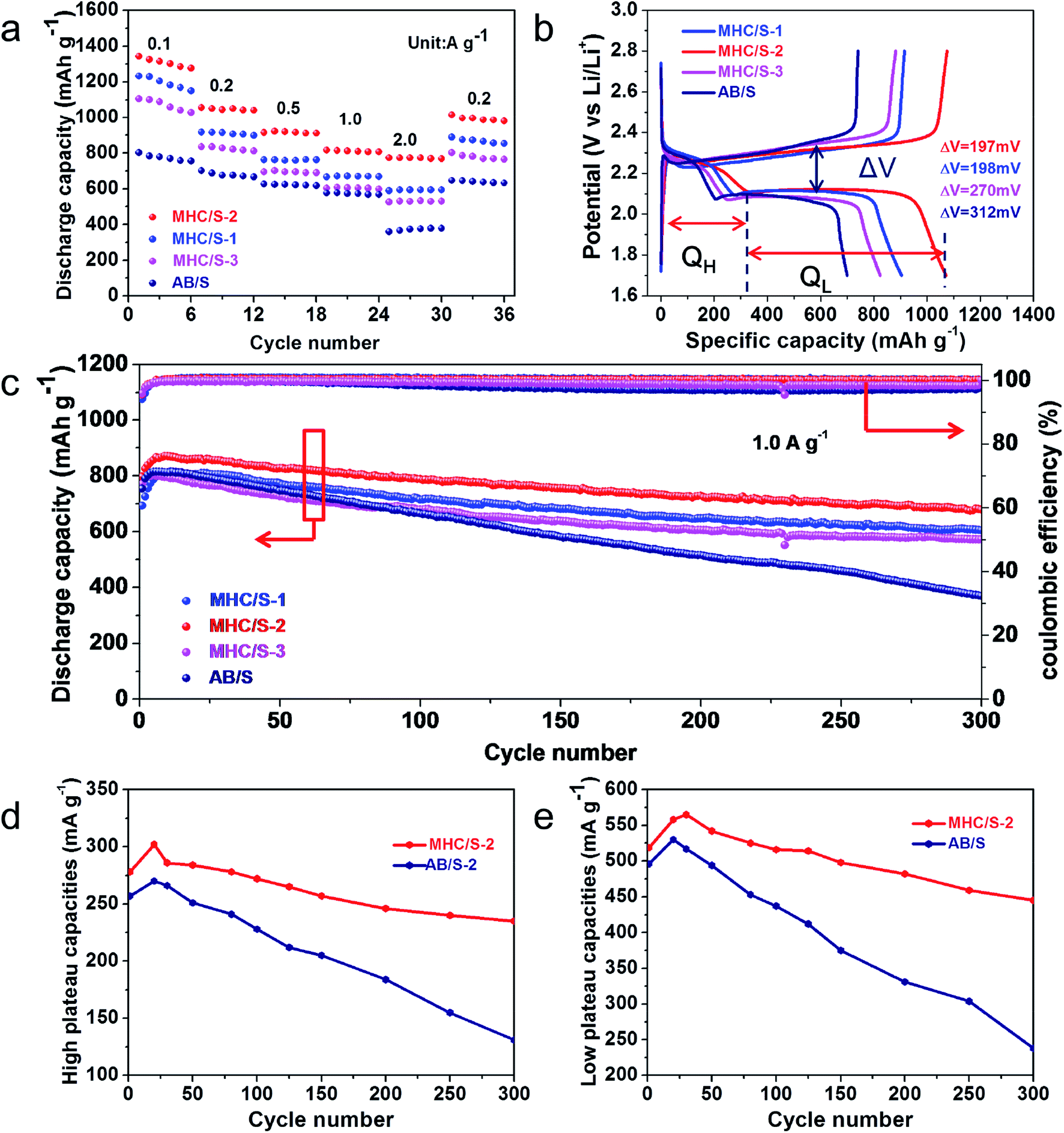 | ||
| Fig. 5 (a) The rate performance of different cells from 0.1–2 A g−1; (b) typical charge–discharge process curve of different cells at 0.2 A g−1; (c) cycling performance of different cells at 1.0 A g−1 for 300 cycles; high plateau (QH) (d) and low plateau (QL) (e) discharge capacities of MHC/S-2 and AB/S at 1.0 A g−1. | ||
Fig. 5b demonstrates the first cycle galvanostatic charge and discharge curves of all samples at 0.2 A g−1. The voltage curves of all cells show the typical two-plateaus behavior, which corresponds to the two-step sulfur redox reactions. The high-potential plateau at around 2.3 V represents the reduction of elemental sulfur into soluble lithium polysulfide (Li2Sn, 4 ≤ n ≤ 8). This step involves 0.5 electron per sulfur atom with a small capacity contribution of 418 mA h g−1. While the long lower-potential plateau at about 2.1 V is associated with the conversion of long-chain lithium polysulfides to insoluble short-chain Li2S2 and Li2S, which involves 1.5 electron per sulfur atom with a theoretical capacity of 1256 mA h g−1.42,43 The MHC/S electrodes delivers smaller potential interval between charge and discharge plateaus, indicating the smaller electrochemical polarization and faster reaction kinetics.44 The long-term cycling performance of different cells at the current density of 1.0 A g−1 are shown in Fig. 5c. The MHC/S-2 cell behaves best among all the samples, it delivers an initial capacity of 797 mA h g−1 and maintains a reversible specific capacity of 680 mA h g−1 after 300 cycles, which implies a low decay rate of 0.049% per cycle. Meanwhile the MHC/S-1 and MHC/S-3 deliver an initial specific capacities of 693 mA h g−1 and 771 mA h g−1, the reversible specific capacities are 605 mA h g−1 and 571 mA h g−1 after 300 cycles. These results may due to MHC-2 could show better synergetic effect between hydrangea-like carbon framework and polar MoO2 as S host to absorb Li2Sx during the charge and discharge process. In comparison, the cell assembled with the AB/S cathode suffers from severe capacity fade with only 371 mA h g−1 after 300 cycles. It is worth noting that the capacity of the initial cycles is higher than that of the first cycle capacity. It appears that the inactive core of sulfur needs a few cycles to be reutilized until it gets exposed to the electrolyte at high current density.45 The enhanced electrochemical performance are attributed to the efficient synergistic effect between N-doped conductive carbon skeleton and polar MoO2 nanoparticles. The hydrangea-like carbon framework can facilitate the uniform dispersion of insulated elemental sulfur and provide pathways for Li+ and electron fast transportation in the dissolution–deposition process of sulfur cathode. The subtle MoO2 nanoparticles dispersed in composites can alleviate the shuttle effect by anchoring polysulfides through strong chemical adsorption. It should be mentioned that the MHC host has a negligible capacity contribution for the electrode in the 1.7–2.8 V voltage range, as evidenced in Fig. S2.†
High plateau (QH) and low plateau (QL) discharge capacities are investigated to find more about the details. As shown in Fig. 5d and e, the cell with MHC/S-2 cathode obtains slightly higher initial QH (278 mA h g−1) and QL (519 mA h g−1) than AB/S cells (QH of 257 mA h g−1 and QL of 496 mA h g−1). However after 300 cycles, MHC/S-2 cell has a considerably higher QH and QL retention (84.5% and 85.7%) than AB/S cell (54.8% and 43.1%), suggesting that MHC can effectively trap polysulfides in the cathode region and accelerate the transformation of the captured polysulfides to Li2S2/Li2S. As a result, an enhanced chemical performance was obtained in the MHC host. In addition, the chemical performance comparison of MHC with other matrix reported in the literatures was shown in Table S2.†
Fig. 6a shows the cyclic voltammogram (CV) curves of the MHC/S-2 cathodes at a sweep rate of 0.1 mV s−1. The cathodic scan exhibits two reduction peaks at 2.25 V and 2.04 V (vs. Li/Li+), which can be assigned to the solid–liquid phase transition process of the elemental sulfur to the long-chain polysulfides species (Li2Sx, 4 < x < 8) and the subsequent liquid–solid phase conversion process of the long chain lithium polysulfides to the insoluble short-chain Li2S2/Li2S, respectively. The sharp reduction peak of MHC/S-2 at 2.04 V suggests strong catalytic ability to promote the conversion of LiPSs to Li2S/Li2S2. In the opposite anodic scan, two overlapped anodic peaks can be found at 2.38 and 2.42 V, which are associated with the reverse conversion from polysulfides to S.46 The slight shift of oxidation peaks to lower voltage position from the second scan is related to the rearrangement of the active materials to a more stable position. The overlapping peak positions and intensities manifest a stable and highly reversible electrochemical reaction.47 As shown in Fig. 6b, the CV curve of MHC/S-2 cell exhibits enhanced current density and sharper peak gap, suggesting that the reaction kinetics were improved.48 Fig. 6c exhibit the first charge and discharge curves of MHC/S-2 cathode at different current densities. Two distinct discharge platforms could be observed in the discharge curves, according well with the two well-separated cathodic peaks in CV curves. As the increase of the current density from 0.1 to 2 A g−1, the discharge capacity gradually decreased and the charge–discharge voltage gap slowly increased. While even at high current density, the typical two platforms in discharge curves still remain. This could be due that the carbon frame improves electrical conductivity and molybdenum dioxide adsorbs lithium polysulfides and catalyzes and accelerates the conversation of polysulfides.
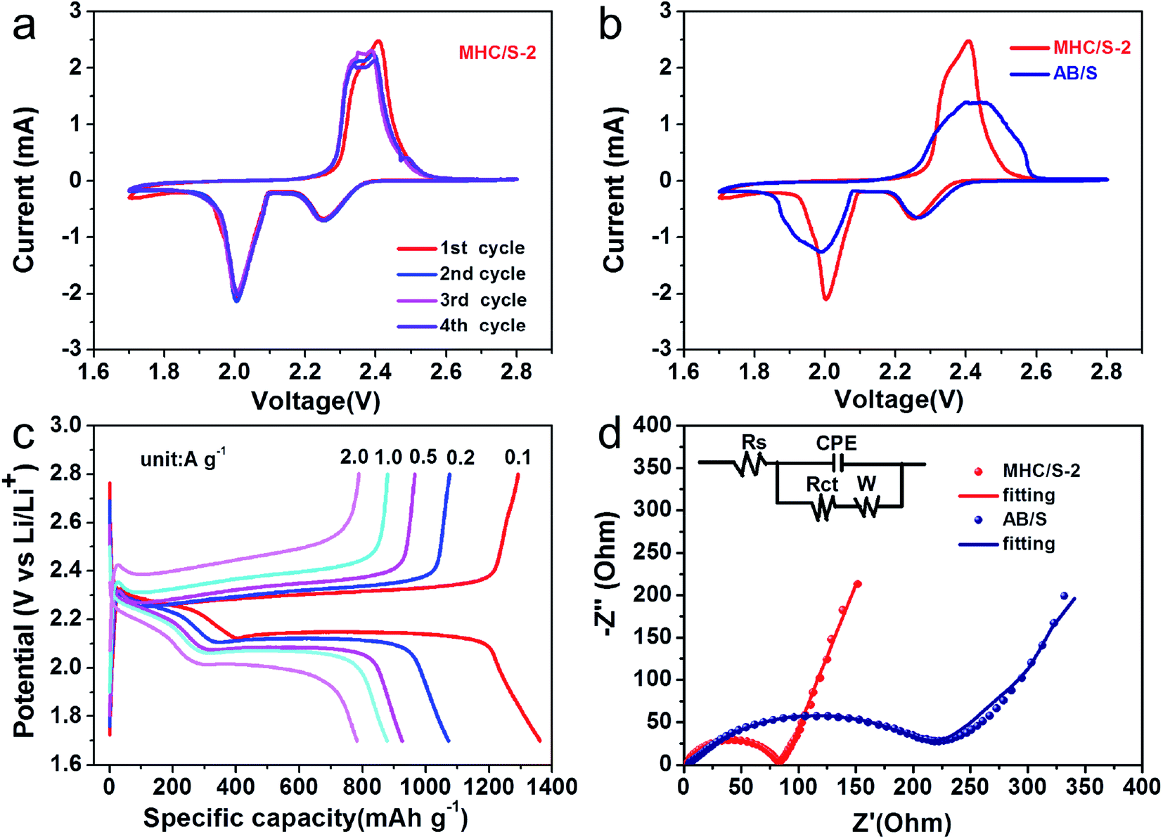 | ||
| Fig. 6 (a) Cyclic voltammogram curve of MHC/S-2 at a scan rate of 0.1 mV s−1; (b) CV of MHC/S-2 and AB/S at a scan rate of 0.1 mV s−1; (c) the discharge–charge curve in different current density MHC/S-2; (d) EIS of three MHC/S and AB/S before cycle (schematic of equivalent circuit inset). | ||
In order to further confirm the improved conductivity and reaction kinetics of the MHC/S cathode, the electrochemical impedance spectroscopy (EIS) measurements of fresh cells were conducted as seen in Fig. 6d. It could be found that there was a depressed semicircle in the high frequency region and an inclined line in the low frequency region in the Nyquist plot. In general, the semicircle in the high frequency region represents the charge transfer resistance (Rct), consistent with the resistance of electrode and electrolyte interface.49 The slope line in the low-frequency region mainly reflects the diffusion of lithium ions into the active materials. The cell with the MHC/S-2 cathode shows smaller semicircle compared with AB/S cathode, suggesting that the MHC promotes fast electron transfer during redox reactions thus facilitating the solid–liquid/liquid–solid electrochemical reactions in LSBs. The corresponding equivalent circuit is shown in the inset of Fig. 6d to further analyze the results of ESI.† We could conclude that the charge transfer resistance (Rct) was 71.3 Ω for MHC/S-2 and 219.1 Ω for AB/S. The smaller charge transfer resistance of the cells with MHC/S-2 cathode indicates the better diffusion dynamics, which is related to a good rate performance.
CV measurements in different scan rates are conducted to further verify the impact of MHC in the redox kinetics (shown in Fig. 7a and S3†). It reveals that the redox peak currents and the square root of scan rate show a linear relationship in Fig. 7b–d, indicating that the rate determined step is controlled by the diffusion process of LiPSs. So the lithium ion diffusion coefficient DLi can be calculated by Randles–Sevick equation:50
| Ip = (2.69 × 10⁵)n1.5AD0.5Cν0.5(25 °C) |
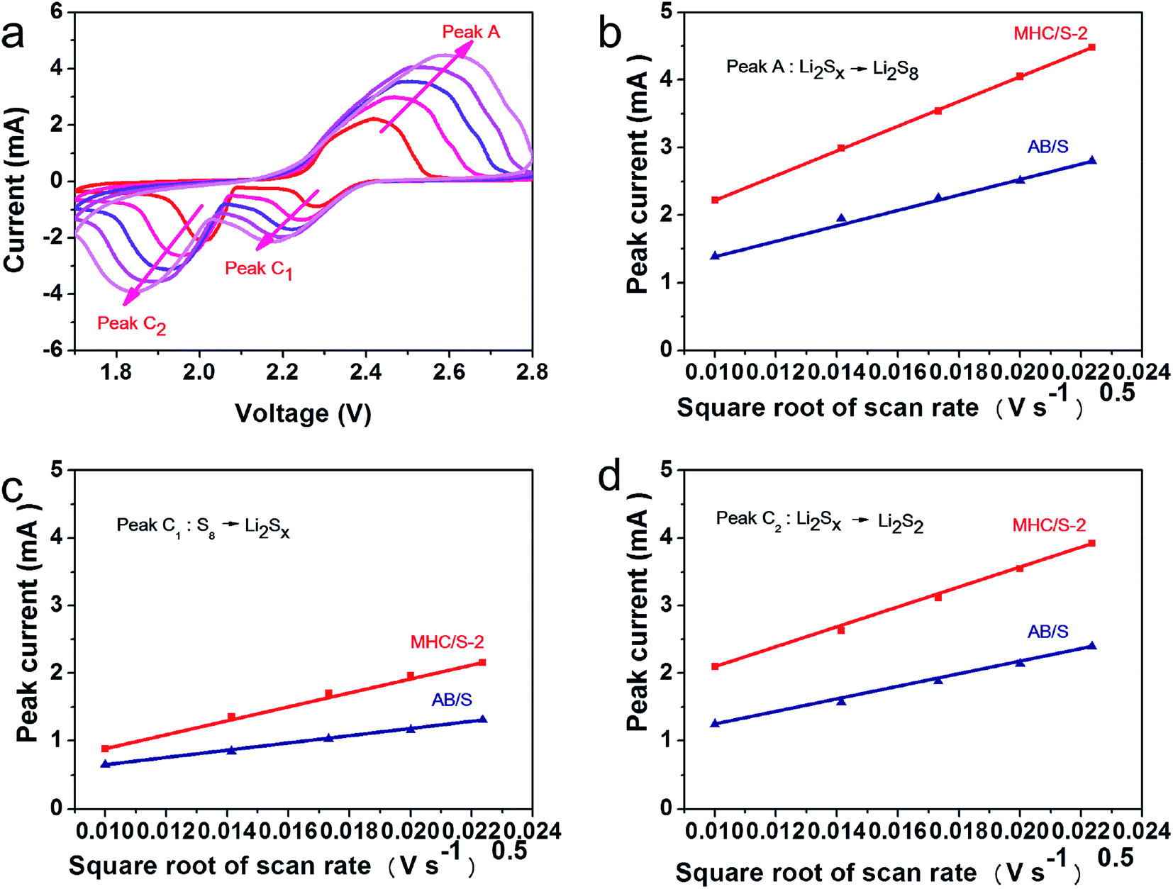 | ||
| Fig. 7 (a) CV curves of MHC/S electrode from 0.1 to 0.5 mV s−1; (b-d) the relationships between the peak current and scan rate in MHC/S-2 and AB/S composites. (b) Peak A: S8 → Li2Sx; (c) peak C1: Li2Sx → Li2S2/Li2S; (d) peak C2: Li2Sx → S8. | ||
To further verify the ability of MHC to constrain polysulfides, the visible adsorption experiment was conducted by soaking a certain amount of MHC-2 powder into the lithium polysulfides solution. The polysulfides (Li2S6 as representation of LixSn) were prepared according to the literature.27 As shown in the inset of Fig. 8a, after resting for 6 h, the light yellow color of Li2S6 solution after impregnation with MHC faded obviously, which vividly suggesting the strong adsorption ability of polysulfide by MHC. Consistent with the above results, the characteristic adsorption peaks of S62− in the visible light range disappears after the static adsorption with MHC, indicative of the reduce of Li2S6 in the solution.52 This means that the MHC has a strong adsorption capacity for lithium polysulfide, which is beneficial to the subsequent conversion and facilitates the utilization of active materials. To further explore the nature of the interaction between MHC and polysulfides, XPS of the solids recovered from the MHC-Li2S6 suspension was studied. In the S 2p spectra of MHC-Li2S6 (Fig. 8b), Peaks at 165.5 and 163.8 are assigned to bridging sulfur and terminal sulfur, respectively. The peak located near 167 eV corresponds to the thiosulfate complex. The peaks at 170.4 and 171.5 eV were attributed to the S–O bond in the polythionate complex. These thiosulfate and polythionate species were formed by the oxidation of polysulfide species.47,53 After adsorption, in the Mo 3d spectra (Fig. 8c), Mo 3d3/2 and 3d5/2 were observed at 232.5 and 229.5 eV corresponding to Mo4+. The peaks at 235.4 and 231.6 eV were corresponded to Mo 3d3/2 and Mo 3d5/2 of Mo6+. Obviously, the Mo 3d peaks slightly shifted to lower bonding energies compared to that of pristine MHC, meaning an increase in the electron cloud density around the Mo atom. These results demonstrated that the strong chemical interaction between MoO2 and the polysulfides was dominated by the Mo–S bond, where the Mo atoms could accept electrons from polysulfide anions.54 The strong chemical interaction between MHC and polysulfides could efficiently restrain the dissolution of the intermediate lithium polysulfides into organic electrolyte, hence boosting the utilization of the active material. To further explore the influence of MHC on the redox process of LiPSs, symmetrical cells employing MHC and AB as working electrodes using Li2S6 electrolyte were assembled. CV tests were performed to research the redox behavior of Li2S6 at the scan rate of 50 mV s−1. As shown in Fig. 8d, the MHC electrode presents a higher redox current density and smaller peak potential separation, indicating that MoO2 not only adsorbs the LiPSs but also catalyzes and accelerates the transformation of LiPSs.
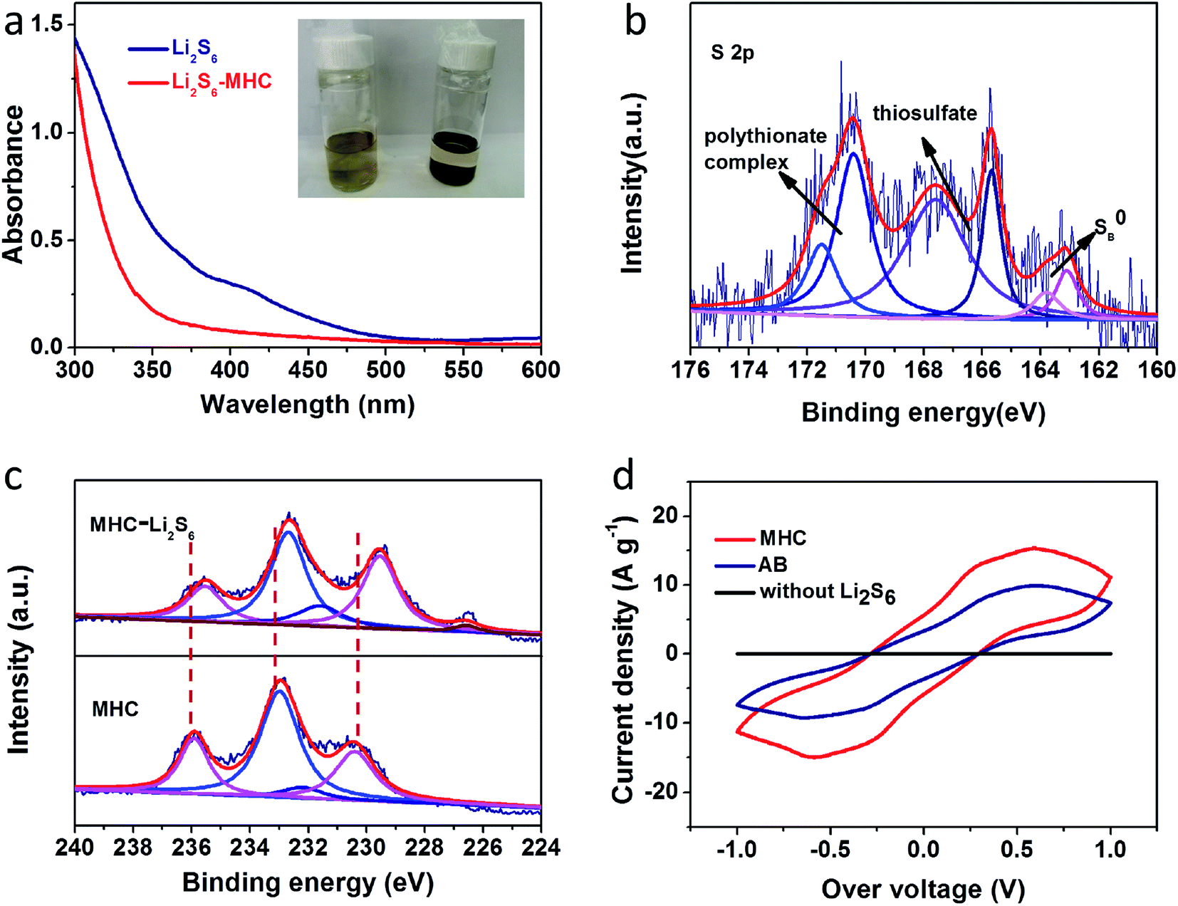 | ||
| Fig. 8 UV-vis absorption spectra (a) of an Li2S6 solution before and after immersing MHC-2 (inset: photograph of pure Li2S6 solution and Li2S6 solution after immersing MHC-2 for 6 h); high-resolution XPS spectra (b) of S 2p for MHC-2 after adsorption; (c) Mo 3d in pure MHC-2 and MHC-2/Li2S6; (d) cyclic voltammetry curves of Li2S6 symmetrical cells employing MHC and AB as working electrodes. | ||
Conclusion
In conclusion, we employed a simple and gentle method for the successful synthesis of the MHC composite, combining porous 3D hydrangea-like carbon networks with highly conductive, polar MoO2 nanoparticles. The N-doped carbon matrix significantly increased the electrical conductivity of the sulfur electrode. MoO2 nanoparticles could effectively adsorb LiPSs due to the strong chemical interaction, which could enhance the charge transfer ability and promote the conversion of lithium polysulfides. The MHC composites showed an exceptional electrochemical properties when were used as sulfur hosts for Li–S batteries. The MHC/S-2 cathode could obtain a discharge capacity of 678 mA h g−1 after 300 cycles at the current density of 1.0 A g−1. This study has verified that MoO2 and carbon composites play an important role in suppressing the dissolution of polysulfides in the electrolyte and increasing the utilization of active materials. The results could also inspire further studies on exploration of other transitional metal oxides with excellent adsorption ability and catalytic effect to polysulfides conversion to promote the practical application of lithium–sulfur battery.Conflicts of interest
There are no conflicts of interest.Acknowledgements
This work was supported by the National Natural Science funds (21534008), Distinguished Young Scholars of Sichuan (20JCQN0197) and Sichuan University-Luzhou city Strategic Cooperation Project (2019CDLZ-06).References
- M. Zhang, W. Chen, L. Xue, Y. Jiao, T. Lei, J. Chu, J. Huang, C. Gong, C. Yan, Y. Yan, Y. Hu, X. Wang and J. Xiong, Adv. Energy Mater., 2019, 10, 1903008 CrossRef.
- L. Fan, M. Li, X. Li, W. Xiao, Z. Chen and J. Lu, Joule, 2019, 3, 361–386 CrossRef CAS.
- M. Wild, L. O'Neill, T. Zhang, R. Purkayastha, G. Minton, M. Marinescu and G. J. Offer, Energy Environ. Sci., 2015, 8, 3477–3494 RSC.
- Q. Cheng, W. Xu, S. Qin, S. Das, T. Jin, A. Li, A. C. Li, B. Qie, P. Yao, H. Zhai, C. Shi, X. Yong and Y. Yang, Angew. Chem., 2019, 58, 5557–5561 CrossRef CAS PubMed.
- S. H. Chung and A. Manthiram, Adv. Mater., 2019, 31, 1901125 CrossRef PubMed.
- A. Manthiram, Y. Fu, S. H. Chung, C. Zu and Y. S. Su, Chem. Rev., 2014, 114, 11751–11787 CrossRef CAS PubMed.
- M. A. Pope and I. A. Aksay, Adv. Energy Mater., 2015, 5, 1500124 CrossRef.
- S. Choi, D. H. Seo, M. R. Kaiser, C. Zhang, T. van der laan, Z. J. Han, A. Bendavid, X. Guo, S. Yick, A. T. Murdock, D. Su, B. R. Lee, A. Du, S. X. Dou and G. Wang, J. Mater. Chem. A, 2019, 9, 4596–4603 RSC.
- S. A. Ahad, P. Ragupathy, S. Ryu, H. W. Lee and D. K. Kim, Chem. Commun., 2017, 53, 8782–8785 RSC.
- Y. Li, J. Fan, J. Zhang, J. Yang, R. Yuan, J. Chang, M. Zheng and Q. Dong, ACS Nano, 2017, 11, 11417–11424 CrossRef CAS PubMed.
- Z. Li, Q. He, X. Xu, Y. Zhao, X. Liu, C. Zhou, D. Ai, L. Xia and L. Mai, Adv. Mater., 2018, 30, 1804089 CrossRef PubMed.
- F. Pei, T. An, J. Zang, X. Zhao, X. Fang, M. Zheng, Q. Dong and N. Zheng, Adv. Energy Mater., 2016, 6, 1502539 CrossRef.
- Y. Qu, Z. Zhang, X. Zhang, G. Ren, Y. Lai, Y. Liu and J. Li, Carbon, 2015, 84, 399–408 CrossRef CAS.
- Y. Zhong, X. Xia, S. Deng, J. Zhan, R. Fang, Y. Xia, X. Wang, Q. Zhang and J. Tu, Adv. Energy Mater., 2018, 8, 1701110 CrossRef.
- G. Li, W. Lei, D. Luo, Y.-P. Deng, D. Wang and Z. Chen, Adv. Energy Mater., 2018, 8, 1702381 CrossRef.
- J. Ren, Y. Zhou, L. Xia, Q. Zheng, J. Liao, E. Long, F. Xie, C. Xu and D. Lin, J. Mater. Chem. A, 2018, 6, 13835–13847 RSC.
- L. Kong, B.-Q. Li, H.-J. Peng, R. Zhang, J. Xie, J.-Q. Huang and Q. Zhang, Adv. Energy Mater., 2018, 8, 1800849 CrossRef.
- H. Wu, L. Xia, J. Ren, Q. Zheng, F. Xie, W. Jie, C. Xu and D. Lin, Electrochim. Acta, 2018, 278, 83–92 CrossRef CAS.
- B. Q. Li, S. Y. Zhang, L. Kong, H. J. Peng and Q. Zhang, Adv. Mater., 2018, 30, 1707483 CrossRef PubMed.
- J. Ren, Y. Zhou, H. Wu, F. Xie, C. Xu and D. Lin, J. Energy Chem., 2019, 30, 121–131 CrossRef.
- X. Zhang, H. Yang, J. Guo, S. Zhao, S. Gong, X. Du and F. Zhang, Nanotechnology, 2017, 28, 475401 CrossRef PubMed.
- Z. Chang, H. Dou, B. Ding, J. Wang, Y. Wang, X. Hao and D. R. MacFarlane, J. Mater. Chem. A, 2017, 5, 250–257 RSC.
- Z. W. Seh, W. Li, J. J. Cha, G. Zheng, Y. Yuan, M. T. McDowell, P.-C. Hsu and Yi Cui, Nat. Commun., 2013, 4, 1331 CrossRef PubMed.
- S. Imtiaz, Z. Ali Zafar, R. Razaq, D. Sun, Y. Xin, Q. Li, Z. Zhang, L. Zheng, Y. Huang and J. A. Anderson, Adv. Mater. Interfaces, 2018, 5, 1800243 CrossRef.
- Y. T. Liu, D. D. Han, L. Wang, G. R. Li, S. Liu and X. P. Gao, Adv. Energy Mater., 2019, 9, 1803477 CrossRef.
- J. Xu, W. Zhang, H. Fan, F. Cheng, D. Su and G. Wang, Nano Energy, 2018, 51, 73–82 CrossRef CAS.
- X. Wu, Y. Du, P. Wang, L. Fan, J. Cheng, M. Wang, Y. Qiu, B. Guan, H. Wu, N. Zhang and K. Sun, J. Mater. Chem. A, 52017, 5, 25187–25192 RSC.
- Y. Huang, Q. Gong, X. Song, K. Feng, K. Nie, F. Zhao, Y. Wang, M. Zeng, J. Zhong and Y. Li, ACS Nano, 2016, 10, 11337–11343 CrossRef CAS PubMed.
- Y. Sun, X. Hu, W. Luo and Y. Huang, J. Mater. Chem., 2012, 22, 425–431 RSC.
- P. Zhang, L. Zou, H. Hu, M. Wang, J. Fang, Y. Lai and J. Li, Electrochim. Acta, 2017, 250, 219–227 CrossRef CAS.
- Y. Liu, R. Rajagopalan, E. Wang, M. Chen, W. Hua, B. Zhong, Y. Zhong, Z. Wu and X. Guo, ACS Sustainable Chem. Eng., 2018, 6, 16105–16112 CrossRef CAS.
- X. Liu, E. Wang, G. Feng, Z. Wu, W. Xiang, X. Guo, J. Li, B. Zhong and Z. Zheng, Electrochim. Acta, 2018, 286, 231–241 CrossRef CAS.
- Z. Sun, Z. Yan, J. Yao, E. Beitler, Y. Zhu and J. M. Tour, Nature, 2010, 468, 549–552 CrossRef CAS PubMed.
- Q. Qu, T. Gao, H. Zheng, Y. Wang, X. Li, X. Li, J. Chen, Y. Han, J. Shao and H. Zheng, Adv. Mater. Interfaces, 2015, 2, 1500048 CrossRef.
- J. Zhang, H. Ye, Y. Yin and Y. Guo, J. Energy Chem., 2014, 23, 308–314 CrossRef CAS.
- Y. M. Sun, X. L. Hu, W. Luo and Y. H. Huang, ACS Nano, 2011, 5, 7100–7107 CrossRef CAS PubMed.
- C. Wang, L. Sun, X. Wang, Y. Cheng, D. Yin, D. Yuan, Q. Li and L. Wang, ChemElectroChem, 2017, 4, 2915–2920 CrossRef CAS.
- C. Wang, L. Sun, F. Zhang, X. Wang, Q. Sun, Y. Cheng and L. Wang, Small, 2017, 13, 1701246 CrossRef PubMed.
- L. Sun, C. Wang, X. Wang and L. Wang, Small, 2018, 14, 1800090 CrossRef PubMed.
- L. C. Yang, W. Sun, Z. W. Zhong, J. W. Liu, Q. S. Gao, R. Z. Hu and M. Zhu, J. Power Sources, 2016, 306, 78–84 CrossRef CAS.
- L. F. Nazar, Adv. Mater., 2015, 27, 6021–6028 CrossRef PubMed.
- C. Zhang, J. J. Biendicho, T. Zhang, R. Du, J. Li, X. Yang, J. Arbiol, Y. Zhou, J. R. Morante and A. Cabot, Adv. Funct. Mater., 2019, 1903842 CrossRef.
- W. Yang, W. Yang, L. Dong, X. Gao, G. Wang and G. Shao, J. Mater. Chem. A, 2019, 7, 13103–13112 RSC.
- W. Yin, Z. Wu, W. Tian, Y. Chen, W. Xiang, G. Feng, Y. Li, C. Wu, C. Xu, C. Bai, B. Zhong, X. Wang, J. Zhang, F. He, A. A. Alshehri and X. Guo, J. Mater. Chem. A, 2019, 7, 17867–17875 RSC.
- Y. S. Su and A. Manthiram, Nat. Commun., 2012, 3, 1166 CrossRef PubMed.
- Y. Li, C. Wang, W. Wang, A. Y. S. Eng, M. Wan, L. Fu, E. Mao, G. Li, J. Tang, Z. W. Seh and Y. Sun, ACS Nano, 2020, 14, 1148–1157 CrossRef CAS PubMed.
- J. Wu, H. Zeng, X. Li, X. Xiang, Y. Liao, Z. Xue, Y. Ye and X. Xie, Adv. Energy Mater., 2018, 8, 1802430 CrossRef.
- Z. Yuan, H. J. Peng, T. Z. Hou, J. Q. Huang, C. M. Chen, D. W. Wang, X. B. Cheng, F. Wei and Q. Zhang, Nano Lett., 2016, 16, 519–527 CrossRef CAS PubMed.
- P. P. R. M. L. Harks, C. B. Robledo, T. W. Verhallen, P. H. L. Notten and F. M. Mulder, Adv. Energy Mater., 2017, 7, 1601635 CrossRef.
- X. Liu, P. Chen, J. Chen, Q. Zeng, Z. Wang, Z. Li and L. Zhang, Electrochim. Acta, 2020, 330, 135337 CrossRef CAS.
- X. Tao, J. Wang, C. Liu, H. Wang, H. Yao, G. Zheng, Z. W. Seh, Q. Cai, W. Li, G. Zhou, C. Zu and Y. Cui, Nat. Commun., 2016, 7, 11203 CrossRef CAS PubMed.
- P. Ji, B. Shang, Q. Peng, X. Hu and J. Wei, J. Power Sources, 2018, 400, 572–579 CrossRef CAS.
- R. Wang, K. Wang, S. Gao, M. Jiang, J. Han, M. Zhou, S. Cheng and K. Jiang, Nanoscale, 2018, 10, 16730–16737 RSC.
- C. Wang, K. Li, F. Zhang, Z. Wu, L. Sun and L. Wang, ACS Appl. Mater. Interfaces, 2018, 10, 42286–42293 CrossRef CAS PubMed.
Footnote |
| † Electronic supplementary information (ESI) available. See DOI: 10.1039/d0ra02102d |
| This journal is © The Royal Society of Chemistry 2020 |