
 Open Access Article
 This Open Access Article is licensed under a Creative Commons Attribution-Non Commercial 3.0 Unported Licence
Investigating the effects of adding hybrid nanoparticles, graphene and boron nitride nanosheets, to octadecane on its thermal properties†
Hossein Tafrishia,
Sadegh Sadeghzadeh *b,
Fatemeh Molaeic and
Hossein Siavoshid
*b,
Fatemeh Molaeic and
Hossein Siavoshid
aSchool of Advanced Technologies, Iran University of Science and Technology, Tehran, Iran
bSchool of Advanced Technologies, Iran University of Science and Technology, Tehran, Iran. E-mail: sadeghzadeh@iust.ac.ir
cMining and Geological Engineering Department, University of Arizona, Arizona, USA
dMining and Geological Engineering Department, University of Arizona, Arizona, USA
First published on 14th April 2020
Abstract
Octadecane is an alkane that is used to store thermal energy at ambient temperature as a phase change material. A molecular dynamics study was conducted to investigate the effects of adding graphene and a boron nitride nanosheet on the thermal and structural properties of octadecane paraffin. The PCFF force field for paraffin, AIREBO potential for graphene, Tersoff potential for the boron nitride nanosheet, and Lennard-Jones potential for the van der Waals interaction between the nanoparticles and n-alkanes were used. Equilibrium and nonequilibrium molecular dynamics simulations were used to study the nano-enhanced phase change material properties. Results showed that the nanocomposite had a lower density change, more heat capacity (except at 300 K), more thermal conductivity, and a lower diffusion coefficient in comparison with pure paraffin. Additionally, the nanocomposite had a higher melting point, higher phonon density of state and radial distribution function peaks.
1 Introduction
N-Paraffins (n-alkanes) are long chains of hydrocarbons with the chemical formula CnH2n+2.1 These materials can be used for thermal energy storage (TES) applications and thermal management.2 Different kinds of paraffins have many advantages such as high latent heat, low cost, and excellent melting temperature range, but an important disadvantage is their low thermal conductivity.3 Using high thermal conductive nanoparticles4 can ameliorate this defect.5 Qu et al.6 studied the effect of a hybrid of expanded graphite (EG) and multi-walled carbon nanotube (MWCNT) on the thermal conductivity enhancement of paraffin. The best result of their study was a 444% enhancement of the thermal conductivity for the hybrid nano-additives. The authors declared that using hybrid nano-additives was more effective than using a single one. A boron nitride nanosheet (BNNS) was used by Fang et al.7 to enhance the thermal energy storage properties of the paraffin-based phase change material (PCM). The result was that the presence of BNNS (up to 10 wt%) increased the thermal conductivity of the nano-enhanced PCM (NEPCM) by up to 60%, while it decreased the latent heat of fusion by about 12%. A graphene nano-platelet (GNP) was used by Fang et al.8 to add to the n-eicosane paraffin. The results show that with the highest loading of 10 wt% of GNP, the thermal conductivity increased by about 400% at 10 °C. However, this addition led to a decrease of 16% in the latent heat capacity (for 10 wt% of GNP).Molecular dynamics simulations have been demonstrated to be a useful tool for researchers to study the thermal properties of paraffin molecules. Every molecule is explicitly considered in this technique. The interaction of each atom with others is calculated using an atomic force field, which is the gradient of the potential energy function.9 Babaei et al.10 designed and simulated octadecane (C18H38) using carbon nanotubes and graphene. They demonstrated that adding carbon nanotubes and graphene improved the thermal conductivity, and decreased the thermal resistance as well. Indeed, by modifying the molecular alignment, these nano additives can increase the heat conductivity. They fixed the nano-additives to survey just the pure paraffin thermal properties. The findings of the non-equilibrium molecular dynamics (NEMD) simulations indicated that the thermal conductivity of paraffin-CNT at 270 K and 300 K was 0.499 and 0.243 W mK−1, respectively. Moreover, this study showed that the thermal conductivity of paraffin–graphene was 0.560 and 0.249 W mK−1 at 270 K and 320 K, respectively, while the pure paraffin thermal conductivity was 0.3 and 0.164 W mK−1 at 270 K and 300 K, respectively. The eicosane system (C20H42) comprising boron nitride was carried out by Rao et al.11 Using an equilibrium molecular dynamics simulation to study the thermal conductivity and other thermal properties, they chose n-eicosane alkane as the paraffin. Two paraffin mixtures, including the boron nitride nanosheet (BNNS) and boron nitride nanotube (BNNT), were simulated. Results revealed that the latent heat of the composites was reduced, in comparison to pure paraffin, after the addition of BN nanostructures. Conversely, the nano-additives significantly improved the thermal conductivity of pure paraffin. As will be shown in this paper, some discrepant results have been observed in these different studies. These differences arose from using different force fields and potentials, calculating several parameters in a wide range of temperatures, and incorporating different nanoparticles in one system, among others. By and large, fixing the nanoparticles and not allowing them to move is not a valid method to calculate the thermal properties of all nanocomposite systems. Additionally, using the equilibrium method for calculating thermal conductivity will produce much higher values for the nano-enhanced PCMs. Therefore, we think this method is not true for these systems. Accordingly, in this paper, we used the nonequilibrium method for the thermal conductivity calculation.
This paper studies the effects of adding nano-additives of graphene and BNNS to n-octadecane paraffin (C18H38). To the best of our knowledge, this has not been studied experimentally or numerically before. The essential contributions of this paper are as follows:
(1) A novel nanocomposite containing graphene and a boron nitride nanosheet was introduced.
(2) Several structural and thermal properties were studied to deeply investigate the PCM and NEPCM behaviors at different temperatures.
(3) The proposed nanocomposite can be used as a NEPCM with better thermo-structural properties.
The rest of this paper is organized as follows: Section 2 explains the modeling structures, how they are built, simulation trends and computational techniques. Section 3 presents the outcomes (including heat capacity, mean square displacement, diffusion coefficient, radial distribution function, phonon density of state, density, and thermal conductivity) and discussion, and finally, Section 4 presents the findings.
2 Materials and methods
2.1 Structures
All simulations were carried out with the package of the massively parallel atomic/molecular simulator (LAMMPS).12 The velocity Verlet algorithm13 was used to numerically incorporate Newton's motion equation. The structures were visualized using Ovito software.14 The octadecane molecule (C18H38), single-layer graphene, and boron nitride nanosheet structures are shown in Fig. 1.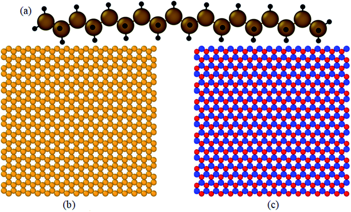 | ||
| Fig. 1 Structure of: (a) an octadecane molecule (C18H38), (b) graphene, and (c) boron nitride nanosheet (BNNS). | ||
The box size for pure paraffin was 65 × 65 × 65 Å3 for 500 octadecane molecules. For the nanocomposite, the size of the box was 75 × 75 × 75 Å3. The graphene and BNNS weight proportions in the composite mixture were approximately 4.9% and 5.1%, respectively. Simulated graphene and BNNS were 38 × 38 Å2. At the beginning of the simulations, the energy of the systems was minimized using the conjugate gradient algorithm.15 Fig. 2(a) indicates the structure of pure paraffin used in simulations after minimization. Fig. 2(b) illustrates the structure of the nano-enhanced PCM, which was used in simulations after minimization. Periodic boundary conditions were employed in all three directions. The number of atoms in each simulation system is reported in Table 1.
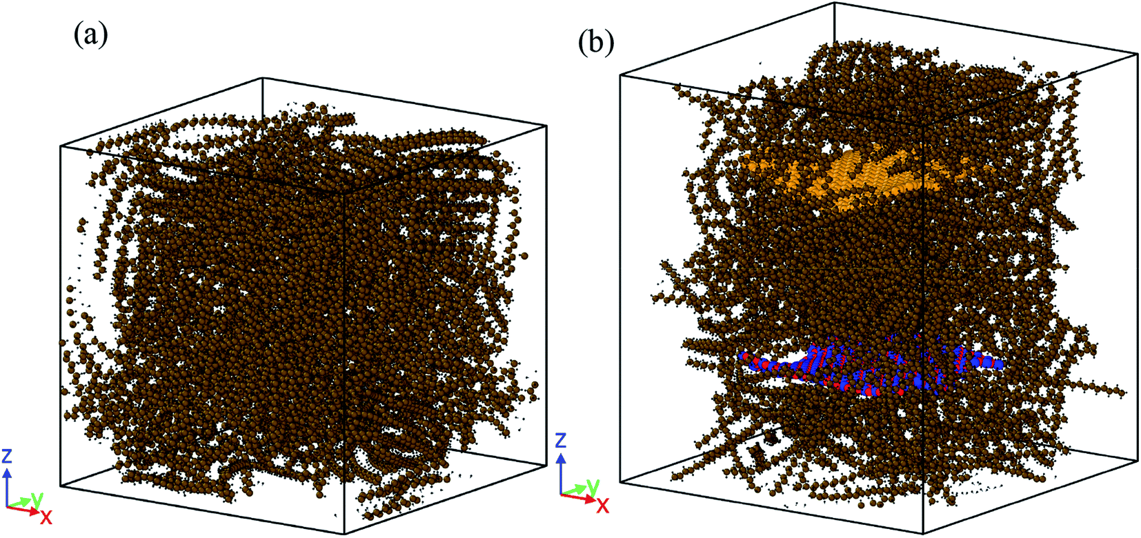 | ||
| Fig. 2 Structures of: (a) the pure paraffin and (b) nano-enhanced PCM used in the simulations after minimization. | ||
| System | # of atoms in paraffin | # of atoms in graphene | # of atoms in BNNS | # of all atoms |
|---|---|---|---|---|
| Pure octadecane | 28![[thin space (1/6-em)]](https://www.rsc.org/images/entities/char_2009.gif) 000 000 |
— | — | 28000 |
| Nanocomposite | 28000 |
576 | 576 | 29152 |
2.2 MD procedure
A PCFF‡ force field16–19 with a cut-off radius of 10 Å was used to simulate the octadecane molecules, and an AIREBO potential with a cut-off radius of 8.5 Å was used to simulate graphene.20 A Tersoff potential21,22 developed by Sevik et al.23,24 was used to characterize the BNNS interactions. The 6–12 Lenard-Jones potential25 was employed in conjunction with the Lorentz–Berthelot mixing rule26 for the van der Waals interaction between the nano-additives and n-alkanes. The cut-off radius of LJ was assumed at 10 Å. The time step was set to 0.5 fs in all simulations. To simulate all structures, four steps were applied. The first step was the melting and crystallization cycle to optimize the structures. During 2 × 10⁶ steps, the structures were heated from 260 K to 340 K under an NPT ensemble27,28 and atmospheric pressure to completely melt. Then, it was cooled down from 340 K to 260 K under an NPT ensemble for 2 × 10⁶ steps to be solidified. Finally, the optimized structure of each system (pure paraffin or nanocomposite PCM) was extracted.In the second step, all structures were simulated at 260, 270, 280, 290, 300, 310, 320, 330, and 340 K. The simulation process was such that under the NPT ensemble, all structures were equilibrated for 2 × 10⁶ time steps of the corresponding temperature (at 1 atm). The output of this section led to various energy fluctuation plots and the final density of the system at the desired temperatures. Subsequently, simulations were followed at the desired temperature for 4 × 10⁶ time steps under the NVT ensemble (the third step). The outputs of this step included the MSD (mean square displacement), D (diffusion coefficient), Cv (heat capacity at constant volume), RDF (radial distribution function), and PDOS (phonon density of state) at several temperatures for every two structures.
Lastly, the structures were simulated for 6 × 10⁶ time steps (3 nanoseconds) under the NVE ensemble to account for their thermal conductivity in the fourth step. The box was divided into several plates along the X/Y/Z direction. Through the simulation box, the heat flux was introduced by adding heat to the molecules inside the heat source (a planar slab) in two regions of the box. The same amount of heat was then extracted from the molecules within another slab (thermal sink) in another region (in the middle of the box). The thermal conductivity of the material in the simulation box (subject to the periodic boundary condition) was calculated after achieving a steady state based on Fourier's law. These simulations were carried out at 280 K (solid-state), 300 K (octadecane melting point) and 320 K (fluid state).
3 Results and discussions
This chapter describes the thermal and structural characteristics of pure paraffin and the nanocomposite, including the heat capacity at constant volume (Cv), mean square displacement (MSD), diffusion coefficient (D), phonon density of state (PDOS), density (ρ), radial distribution function and thermal conductivity (kappa). Fig. 3 displays the kinetic and potential energy fluctuations of pure paraffin and the nanocomposite at 300 K. According to Fig. 3, all systems were thoroughly equilibrated.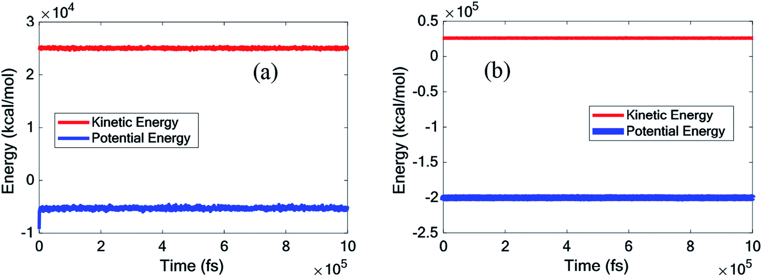 | ||
| Fig. 3 Kinetic and potential energy fluctuations of (a) the pure octadecane, (b) octadecane–graphene–BNNS nanocomposite under NPT equilibrium at 300 K. | ||
3.1 Validation
To validate the performed simulations, the density and thermal conductivity obtained for pure octadecane were compared with those of previous works. Since there is no similar study, comparing the outcomes of the current work for the nanocomposite was difficult. The results of this study, as shown in Table 2, aligned well with those outlined in prior works,10,29–33 and the simulations conducted in this work could be appropriately validated.| Temperature (K) | Applied method | Density (g cm−3) | Thermal conductivity (W mK−1) | Reference |
|---|---|---|---|---|
| 280 | MD (PCFF) | 0.7356 | 0.1194 | Current study |
| 290 | MD (PCFF) | 0.7303 | — | Current study |
| 300 | MD (PCFF) | 0.7184 | 0.1227 | Current study |
| 310 | MD (PCFF) | 0.7130 | — | Current study |
| 320 | MD (PCFF) | 0.7024 | 0.1180 | Current study |
| 298.15 | MD (COMPASS) | — | 0.277–0.303 | Liu et al.29 |
| 270 | MD (NERD) | — | 0.30 | Babaei et al.10 |
| 290 | MD (NERD) | 0.86 | — | Babaei et al.10 |
| 300 | MD (NERD) | — | 0.164 | Babaei et al.10 |
| 310 | MD (NERD) | 0.75 | — | Babaei et al.10 |
| 293–297 (solid phase) | Experimental | 0.91 | — | Gülseren et al.30 |
| 301–308 (liquid phase) | Experimental | 0.778 | — | Gülseren et al.30 |
| 300 (liquid phase) | Experimental | — | 0.153 | Powell et al.31 |
| 275 (solid phase) | Experimental | — | 0.33 | Yarbrough et al.32 |
| 294–300 (solid phase) | Experimental | — | 0.1505 | Xia et al.33 |
3.2 The latent heat capacity
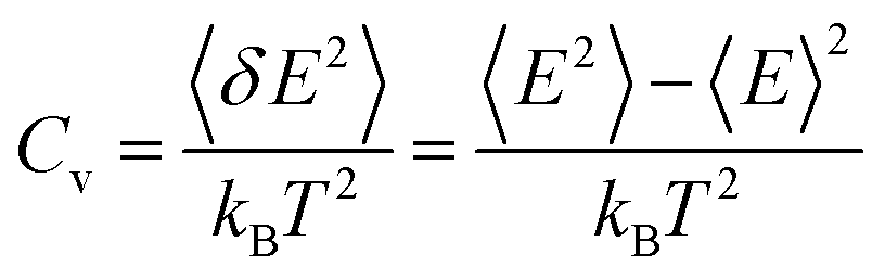
For paraffin as a PCM, the latent heat is so important. The heat capacity is a very serious and substantial issue, especially at melting temperatures. The thermal capacity was calculated as follows under a constant volume (Cv):
 | (1) |
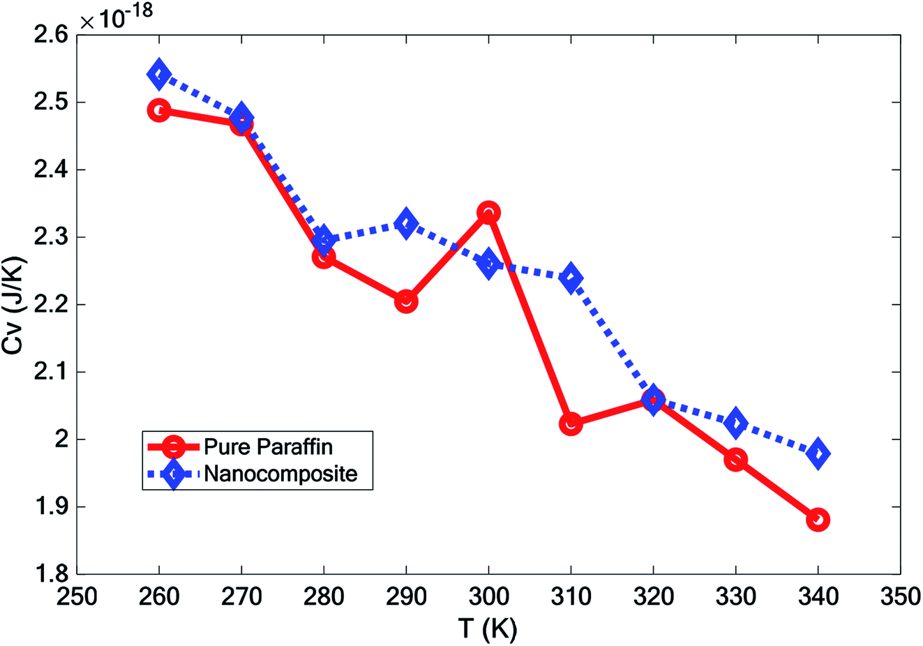 | ||
| Fig. 4 Heat capacity of pure paraffin and the nanocomposite at different temperatures. | ||
3.3 Mean square displacement
The mean square displacement (MSD), which implies a measure of all particles' average range through time, is generally used to define the system conduct during a phase change. eqn (2) was used to calculate the mean square displacement (MSD):
 | (2) |
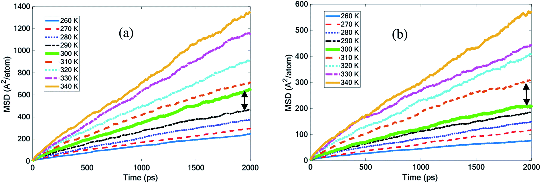 | ||
| Fig. 5 Mean square displacement with temperature for (a) pure octadecane and (b) the octadecane–graphene–BNNS nanocomposite. | ||
Fig. 5(a) demonstrates that by increasing the octadecane temperature, the slope of the MSD diagram increased. It seemed that the slope of the MSD curve for octadecane grew considerably, becoming more steep at temperatures of 300 K and above. According to the experiments, the melting point was 300 K and this finding was quite close to it.30 The curves in Fig. 5(b) describe how MSD changed in the octadecane–graphene–BNNS nanocomposite at different temperatures. The nanocomposite continued to be solid up to 300 K, and then was melted at 310 K. This result confirms that the nano-additives increased the paraffin melting point by approximately 10 K.
3.4 Diffusion coefficient
According to the Einstein equation,34 the self-diffusion coefficient (D) was calculated as follows:
 | (3) |
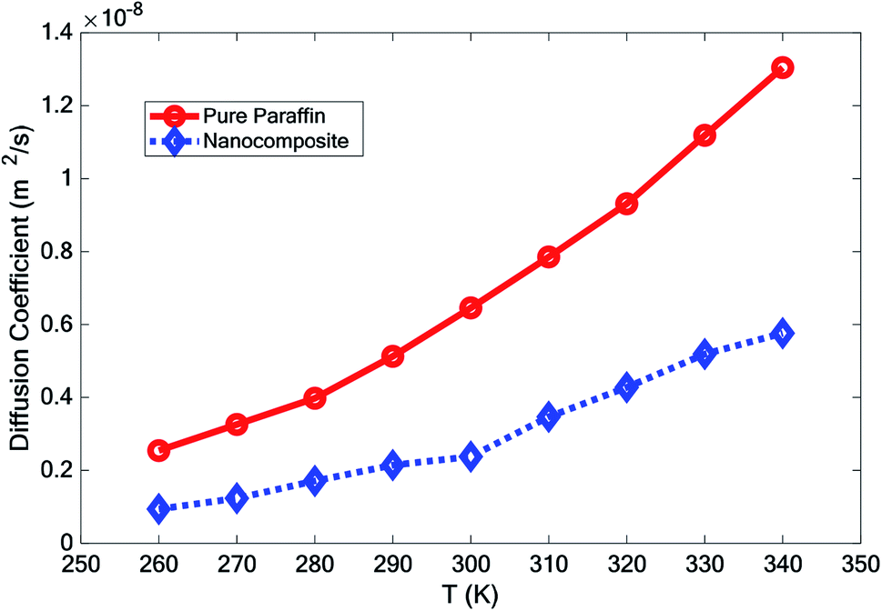 | ||
| Fig. 6 The diffusion coefficient of simulated structures vs. temperature. | ||
3.5 Density
The effect of adding nano-additives on the density of paraffin was investigated. Fig. 7 compares the density of the simulated structures at different temperatures. The density ratio was defined as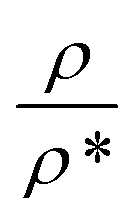 , where ρ is density and ρ* is the density at T = 260 K. According to Fig. 7, the density of the systems decreased as the temperature increased. However, the slope of this reduction for the nanocomposite was less than that for pure paraffin. Also, the results showed that the addition of graphene and the boron nitride nanosheet caused an increase in the density of the nano-enhanced PCM.
 | ||
| Fig. 7 Variation of the density of the simulated structures vs. temperature. | ||
3.6 Phonon density of state
The phonon density of state (PDOS) was obtained by calculating the Fourier transform of the velocity autocorrelation function (indicated by 〈 〉) using the following equation:
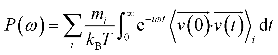 | (4) |
 , and ω are the mass, velocity, and phonon angular frequency, respectively.
Fig. 8 shows the PDOS for pure paraffin, and the mixture at 260, 300, and 340 K. The PDOS of pure paraffin had some peaks between 20 to 45 THz and in 90 THz, which was inconsistent with ref. 35. Another peak for pure paraffin was between 0 to 5 THz. The existence of graphene and BNNS caused higher peaks and troughs, and also caused other new peaks between 0 to 55 THz. With increasing temperature in both pure paraffin and the nanocomposite, the peaks of PDOS also increased.
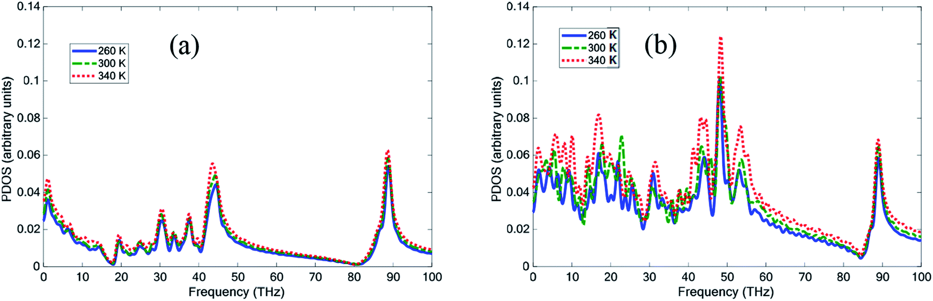 | ||
| Fig. 8 Phonon density of state (PDOS) of (a) pure paraffin and (b) the nanocomposite at temperatures 260 K, 300 K, and 340 K. | ||
3.7 Radial distribution function
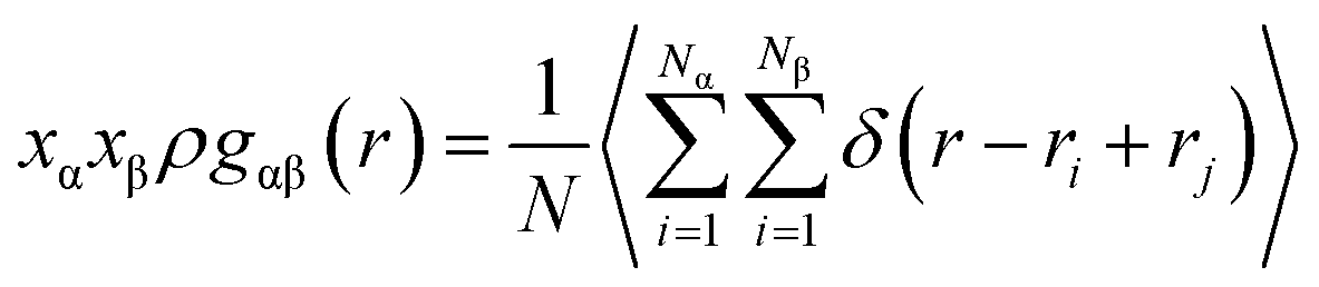
The radial distribution function is the probability of the presence of particles, which is calculated by assuming the spherical shells around a particle with different radii. RDF counts the number of atoms around a specific particle in each of these shells. The RDF, represented by the symbol gαβ(r), as defined by Hansen and McDonald,36 is calculated with eqn (3):
 | (5) |
It is a measure of the probability of finding a particle at a distance of r away from a given reference particle. The general algorithm involves determining how many particles are within a distance of r and r + dr away from a particle (particle at each bin). N denotes the number of total atoms, Ni represents the number of atoms corresponding to the chemical type i (α and β subscriptions indicate the different types of chemicals), x is the mole fraction of chemical type α and β, and ρ is the density of the atoms.
Fig. 9 depicts the RDF curve of the two structures, pure PCM and nano-enhanced PCM (NEPCM) at different temperatures. This figure illustrates the radial distribution function for all atoms relative to each other. The RDFs displayed relatively isolated peaks at low temperatures. It implies that there were constant distances between the two atoms of interest that were characteristic of a solid-state. On the other hand, they became smoother for liquid materials. The RDF of NEPCM had more peaks than PCM.
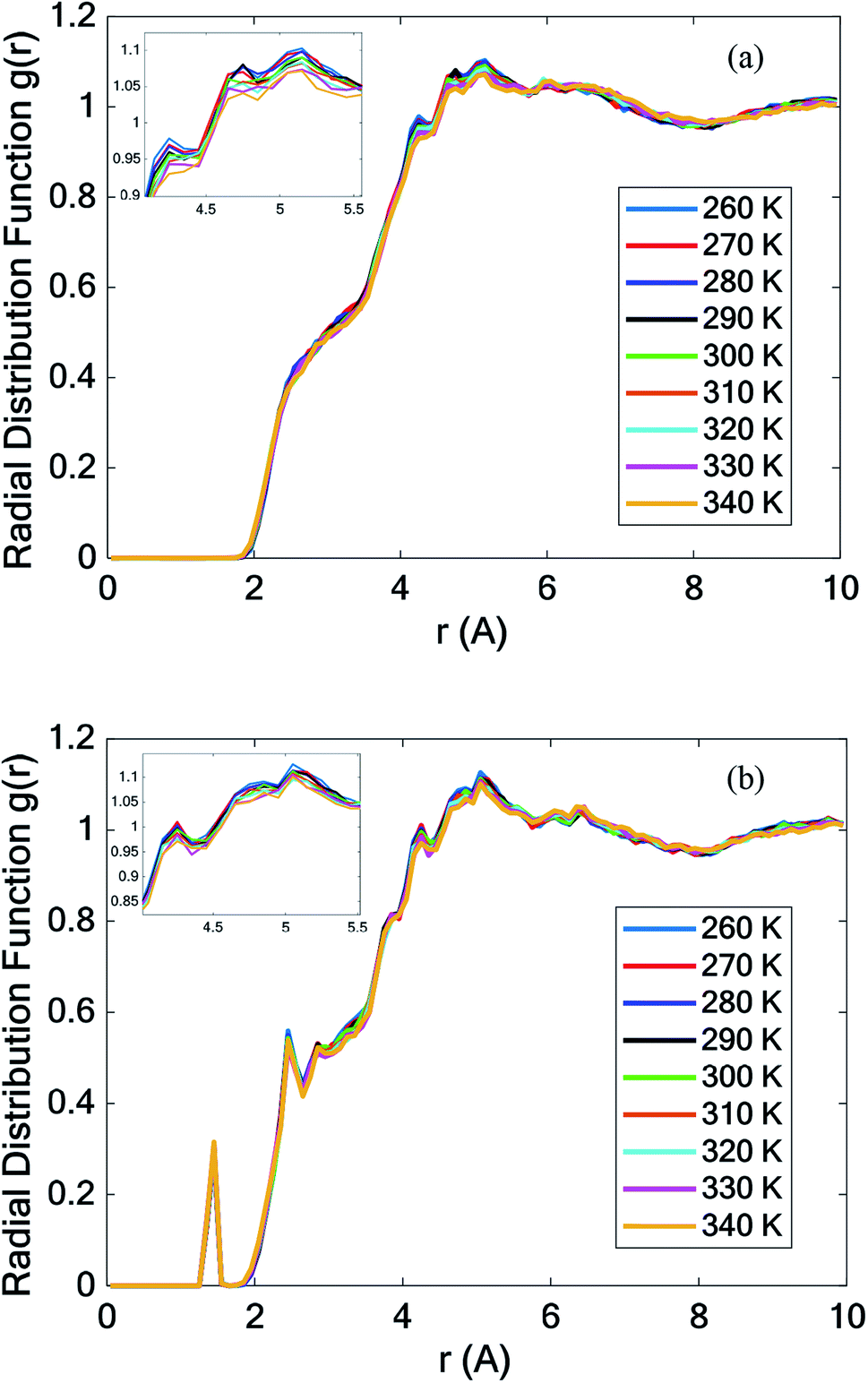 | ||
| Fig. 9 Total radial distribution function (RDF) of (a) all pure octadecane atoms and (b) all octadecane–graphene–BNNS atoms. | ||
3.8 Thermal conductivity
The simulation box was divided into several bins to measure the thermal conductivity in this study. The structure was heated via two heat sources at its left and right ends. A heat sink was assumed in the middle of the structure to dissipate the imposed heat and guarantee the equilibrium. Fig. 10 displays a corresponding schematic diagram for calculating the thermal conductivity in the x-, y-, and z-directions by the nonequilibrium molecular dynamics method.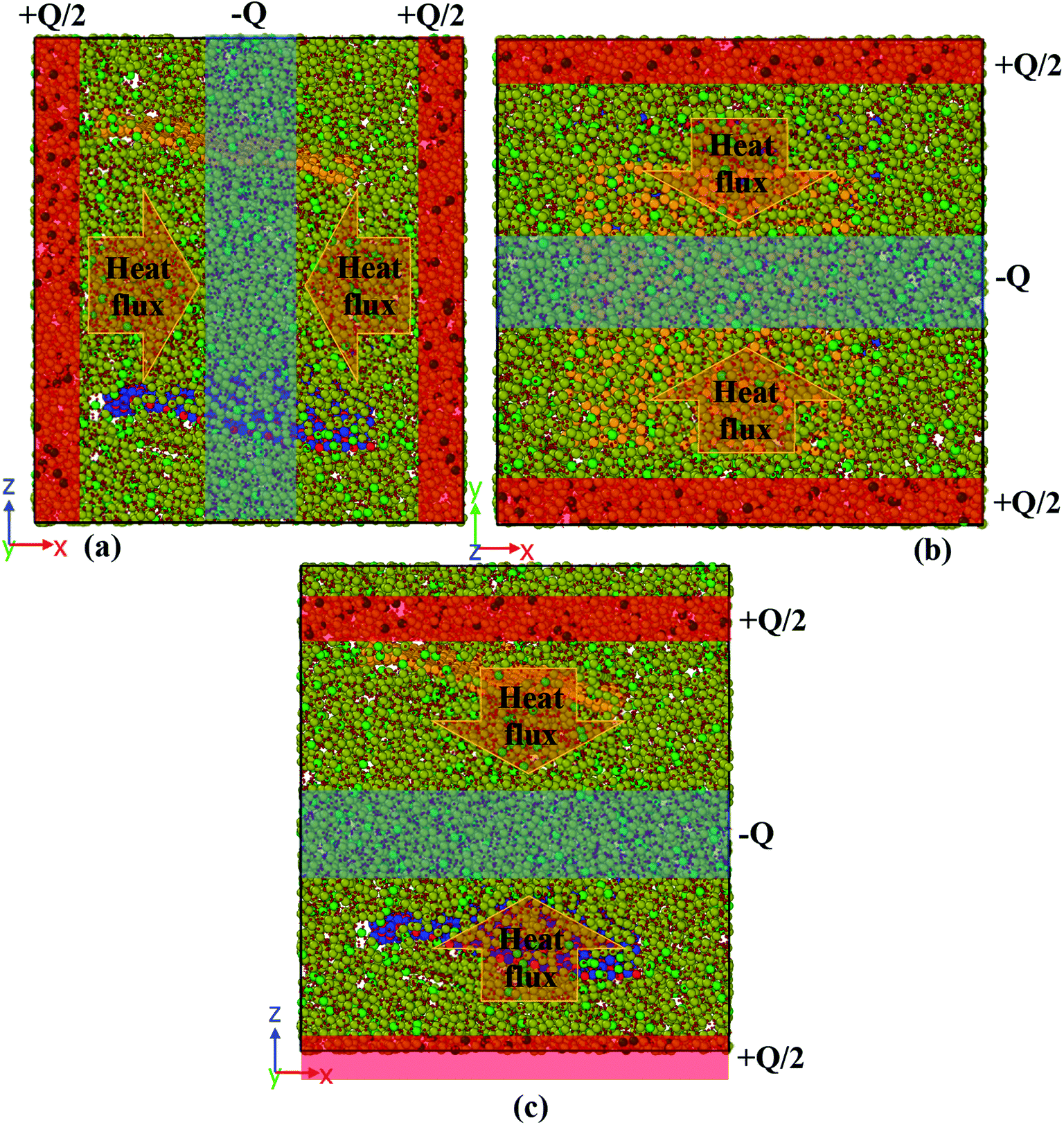 | ||
| Fig. 10 A schematic diagram of the simulation box for calculating the thermal conductivity in the (a) x-direction, (b) y-direction, and (c) z-direction. | ||
The heat flux Q (0.01 kcal mol−1 fs−1 for pure paraffin and 0.03 kcal mol−1 fs−1 for the nanocomposite) was applied between the heat sources and sinks under the microcanonical ensemble. As the kinetic energy of the atoms of the hot slab increased and the kinetic energy of the atoms of the cold slab decreased, this energy transferred from warmer atoms to colder atoms. Simulations of the thermal conductivity under the microcanonical ensemble for 3 ns (6 million time steps) were performed. Using the temperature output for the atoms of each part of the box along the box length, the temperature-position profile was plotted, and the thermal conductivity was calculated using Fourier's law as follows:
 | (6) |
In this equation,  is the rate of the heat addition to heat sources or the heat extraction from the heat sink. ‘A’ is the cross-sectional area of the simulation box perpendicular to the direction of the imposed heat flux, whereas
  and
and  are the temperature gradients on the linear section of the temperature-position curve for the left section and right section of the curve. This means that the temperature of the hot and cold sections was not included in calculating the temperature gradient. The heat sink was in the middle of the box with a thickness of 2 nm and the heat sources were in the two sides of the box, which were joined together as a union region, with 2 nm thickness. This means the thickness of each hot region was 1 nm.
Fig. S1† illustrates the temperature profiles of the pure octadecane in the x-, y-, and z-directions at 280 K (solid phase). Fig. S2 and S3† show the temperature-position profiles at 300 K (melting point) and 320 K (liquid phase), respectively, in different directions of pure octadecane paraffin. Thermal conductivities of paraffin at various temperatures in the x-, y-, and z-directions were calculated according to the corresponding graphs, and are presented in Table 3. The highest thermal conductivity of paraffin was obtained at the melting point.
| Temperature (K) | kx (W mK−1) | ky (W mK−1) | kz (W mK−1) | kmean (W mK−1) |
|---|---|---|---|---|
| 280 | 0.11242 | 0.11921 | 0.12659 | 0.1194 |
| 300 | 0.12277 | 0.12246 | 0.12294 | 0.1227 |
| 320 | 0.11652 | 0.11681 | 0.12052 | 0.1180 |
Investigating the effects of adding graphene and the boron nitride nanosheet to paraffin and understanding the variation of thermal transport in different temperatures is the purpose of this section. Fig. S4–S6† display the temperature profiles of the octadecane–graphene–BNNS nanocomposite in the x-, y-, and z-directions at different temperatures. The thermal conductivity of the nanocomposite at various temperatures and directions is calculated according to the corresponding graphs, and are presented in Table 4. The nano-additives improve paraffin's thermal conductivity. With increasing temperature, the enhancement of the thermal conductivity increased. This may be because of the higher peaks of the phonon density of state at high temperatures.
| Temperature (K) | kx (W mK−1) | ky (W mK−1) | kz (W mK−1) | kmean (W mK−1) | Mean kappa changes compared to pure paraffin |
|---|---|---|---|---|---|
| 280 | 0.16054 | 0.15231 | 0.12793 | 0.1469 | +23.0% |
| 300 | 0.16857 | 0.15731 | 0.13957 | 0.1552 | +26.5% |
| 320 | 0.16054 | 0.16124 | 0.13026 | 0.1507 | +27.7% |
According to the results, the maximum thermal conductivity was observed for the nanocomposite at 300 K. In both systems, the highest thermal conductivity occurred at 300 K.
4 Conclusion
In this paper, the effect of adding hybrid nanoparticles, graphene, and BNNS to octadecane and a consideration of its thermal conductivity were studied using molecular dynamics. The paraffin form studied was octadecane (C18H38), with a melting point of approximately 300 K. The effects of different temperatures on the density, melting point, diffusion coefficient, heat capacity, and thermal conductivity were investigated. The measurement of density showed that by adding nano-additives, the density increased. Furthermore, with increasing temperature, the density decreased. However, the density reduction for the nanocomposite was lower than that for pure paraffin. The mean square displacement of different structures at various temperatures indicated that graphene and the BNNS nano-additives improved the melting point of octadecane by about 10 K.It was observed that with increasing temperature, the diffusion coefficient also increased. However, the diffusion coefficient of the nanocomposite was lower than that for pure paraffin. Studying the thermal conductivity of different structures revealed that the addition of the nano-additives increased the thermal conductivity of paraffin by about 23.0%, 26.5% and 27.7% at 280 K, 300 K, and 320 K, respectively. By adding the nano-additives, the heat capacity of the phase change material was enhanced at all temperatures, except for at 300 K.
Conflicts of interest
There is no conflict of interest.Acknowledgements
The authors would like to thank Dr F. Yousefi and P. Khoshbakht Marvi for their useful comments on this work.References
- S. Kahwaji, M. B. Johnson, A. C. Kheirabadi, D. Groulx and M. A. White, Energy, 2018, 162, 1169–1182 CrossRef CAS
.
- R. Heydarian, M. B. Shafii, A. Rezaee Shirin-Abadi, R. Ghasempour and M. Alhuyi Nazari, J. Therm. Anal. Calorim., 2019, 137, 1603–1613 CrossRef CAS
- L. Qiu, Y. Ouyang, Y. Feng and X. Zhang, Renewable Energy, 2019, 140, 513–538 CrossRef CAS
- H. Zhan, Y. Nie, Y. Chen, J. M. Bell and Y. Gu, Adv. Funct. Mater., 2020, 30, 1903841 CrossRef CAS
- A. Nematpour Keshteli and M. Sheikholeslami, J. Mol. Liq., 2019, 274, 516–533 CrossRef CAS
- Y. Qu, S. Wang, D. Zhou and Y. Tian, Renewable Energy, 2020, 146, 2637–2645 CrossRef CAS
- X. Fang, L.-W. Fan, Q. Ding, X.-L. Yao, Y.-Y. Wu, J.-F. Hou, X. Wang, Z.-T. Yu, G.-H. Cheng and Y.-C. Hu, Energy Convers. Manage., 2014, 80, 103–109 CrossRef CAS
- X. Fang, L.-W. Fan, Q. Ding, X. Wang, X.-L. Yao, J.-F. Hou, Z.-T. Yu, G.-H. Cheng, Y.-C. Hu and K.-F. Cen, Energy Fuels, 2013, 27, 4041–4047 CrossRef CAS
- M. A. González, École thématique de la Société Française de la Neutronique, 2011, 12, 169–200 CrossRef
- H. Babaei, P. Keblinski and J. M. Khodadadi, Int. J. Heat Mass Transfer, 2013, 58, 209–216 CrossRef CAS
- C. Lin and Z. Rao, Appl. Therm. Eng., 2017, 110, 1411–1419 CrossRef CAS
- S. Plimpton, J. Comput. Phys., 1995, 117, 1–19 CrossRef CAS
- L. Verlet, Phys. Rev., 1967, 159, 98–103 CrossRef CAS
- A. Stukowski, Modell. Simul. Mater. Sci. Eng., 2009, 18, 015012 CrossRef
- J. R. Shewchuk, An Introduction to the Conjugate Gradient Method Without the Agonizing Pain, Carnegie Mellon University, 1994 Search PubMed
- H. Sun, J. Phys. Chem. B, 1998, 102, 7338–7364 CrossRef CAS
- H. Sun, Macromolecules, 1995, 28, 701–712 CrossRef CAS
- H. Sun, S. J. Mumby, J. R. Maple and A. T. Hagler, J. Am. Chem. Soc., 1994, 116, 2978–2987 CrossRef CAS
- H. Sun, P. Ren and J. R. Fried, Comput. Theor. Polym. Sci., 1998, 8, 229–246 CrossRef CAS
- S. J. Stuart, A. B. Tutein and J. A. Harrison, J. Chem. Phys., 2000, 112, 6472–6486 CrossRef CAS
- J. Tersoff, Phys. Rev. B: Condens. Matter Mater. Phys., 1988, 37, 6991 CrossRef PubMed
- J. Tersoff, Phys. Rev. B: Condens. Matter Mater. Phys., 1989, 39, 5566–5568 CrossRef PubMed
- C. Sevik, A. Kinaci, J. B. Haskins and T. Çağın, Phys. Rev. B: Condens. Matter Mater. Phys., 2011, 84, 085409 CrossRef
- C. Sevik, A. Kinaci, J. B. Haskins and T. Çağın, Phys. Rev. B: Condens. Matter Mater. Phys., 2012, 86, 075403 CrossRef
- A. K. Rappé, C. J. Casewit, K. S. Colwell, W. A. Goddard III and W. M. Skiff, J. Am. Chem. Soc., 1992, 114(25), 10024–10035 CrossRef
- M. P. Allen and D. J. Tildesley, Computer simulation of liquids, Oxford University Press, 2017 Search PubMed
- W. G. Hoover, Phys. Rev. A: At., Mol., Opt. Phys., 1985, 31, 1695–1697 CrossRef PubMed
- H. C. Andersen, J. Chem. Phys., 1980, 72, 2384–2393 CrossRef CAS
- X. Liu and Z. Rao, J. Energy Inst., 2019, 92(1), 161–176 CrossRef CAS
- İ. Gülseren and J. N. Coupland, Cryst. Growth Des., 2007, 7, 912–918 CrossRef
- R. W. Powell, A. R. Challoner and W. F. Seyer, Ind. Eng. Chem., 1961, 53, 581–582 CrossRef CAS
- D. W. Yarbrough and C.-N. Kuan, Therm. Conduct., 1981, 17, 265–274 Search PubMed
- Y. Xia, W. Cui, H. Zhang, F. Xu, L. Sun, Y. Zou, H. Chu and E. Yan, J. Mater. Chem. A, 2017, 5, 15191–15199 RSC
- C.-G. Tao, H.-J. Feng, J. Zhou, L.-H. Lv and X.-H. Lu, Acta Phys.-Chim. Sin., 2009, 25, 1373–1378 CAS
- Y. Wang, C. Yang, Y. Cheng and Y. Zhang, RSC Adv., 2015, 5, 82638–82644 RSC
- J.-P. Hansen and I. R. McDonald, Theory of simple liquids, Elsevier, 1990 Search PubMed
Footnotes |
| † Electronic supplementary information (ESI) available. See DOI: 10.1039/d0ra01847c |
| ‡ Polymer consistent force field. |
| This journal is © The Royal Society of Chemistry 2020 |