
 Open Access Article
 This Open Access Article is licensed under a Creative Commons Attribution-Non Commercial 3.0 Unported Licence
UiO-67 metal–organic gel material deposited on photonic crystal matrix for photoelectrocatalytic hydrogen production†
Shujian Sun ,
Peisen Liao,
Lihua Zeng,
Lanqi He and
Jianyong Zhang*
,
Peisen Liao,
Lihua Zeng,
Lanqi He and
Jianyong Zhang*
MOE Laboratory of Polymeric Composite and Functional Materials, School of Materials Science and Engineering, Sun Yat-Sen University, Guangzhou 510275, China. E-mail: zhjyong@mail.sysu.edu.cn
First published on 14th April 2020
Abstract
Robust UiO-67 metal–organic framework nanoparticles have been precisely and uniformly anchored on the surface of a photonic crystal via metal–organic gelation, resulting in a nanoscale UiO-67 composite. Mott–Schottky measurements indicate that UiO-67/B is an n-type semiconductor with electron conduction, and the band gap significantly decreases with the assistance of the photonic crystal matrix with a band gap of 0.75 eV. Benefiting from the abundant photoelectrons trapped from the photonic crystal, good hydrogen evolution reaction performance is achieved under light irradiation. The current density increases from 3.2 to 7.0 mA cm−2 at −0.6 V (vs. RHE) for UiO-67/B. The optimized carrier density obtained from UiO-67/B is apparently increased 2.15 times under light irradiation for 30 min. This work provides a rational strategy to address the photo-capture and energy transfer issues of metal–organic frameworks under visible light irradiation for H2 production in artificial photosynthesis.
Introduction
Solar energy, mainly used as thermal radiation energy, is attractive when solar fuels are strategies to address the energy crisis. In fact, the utilization of solar energy can be in two ways: photo-thermal conversion and photo-electric conversion.1 The process of artificial photosynthesis aims to build a solar energy conversion system which is consistent with the fundamental scientific principles derived from the natural process.2 Yet it is still a challenge to find excellent catalysts that play a key role in this process with good durability and catalytic efficiency.3,4 Metal–organic frameworks (MOFs), self-assembled through coordination bonds between metal ions/clusters nodes and organic linkers, have been researched and shown to have high electrocatalytic or photocatalytic activity toward the production of hydrogen, oxygen, and so on.5 As promising candidates zirconium-based MOFs exhibit unprecedented stability,6–8 mainly attributed to their stable Zr6O4(OH)4(CO2)12 nodes.7,9 A typical representative of the Zr-MOF series, UiO-67 has been shown to have ionic channels for effective solvation of lithium ions benefiting from its larger pore channels (1.2–2.3 nm).9–11 UiO-67 can maintain the physical integrity of electrode microstructures and mitigate the rate of anode degradation that presently limits the lifetime of anodes.12 Furthermore, some strategies for applying UiO-67 in photocatalysis are usually to load photoactive species comprising multicomponent molecular Re, Ru or Ir complexes into its structure, resulting in higher quantum efficiency or turnover number.13–18 However, MOFs with good light absorption performance are limited because of their inherent broad energy band. Some strategies have shown that decreasing the energy band can be achieved by increasing the conjugation in the linker through amino or nitro groups.19,20 Different from typical inorganic semiconductors or organic semiconductors that allow charge carrier mobility through their delocalized valence or orbitals, MOFs exhibit light absorption activity similar to that of a semiconductor due to charge transfer from ligand to metal or from ligand to ligand.21–24 However, it still remains a challenge to develop a MOF-based system with high catalytic efficiency that can efficiently utilize the full solar spectrum for photocatalysis.Photonic crystals have been discovered in butterfly wings with bright colour, where light interacts with the three-dimensional (3D) biological structure resulting in a correlation between refractive index and visible wavelengths.25 In particular, photonic structures can assist light collection and trapping of low-energy photons,26 which is an extremely important medium for photocatalysis and photovoltaics.27 In addition, the low reflectivity of black scales results in strong light absorption.28,29 The butterfly-based bio-templates are effective in photocatalysis for light harvesting because of the special microstructures.30 The light absorbed by a butterfly-based support can promote the transformation of semiconductor behaviours via energy transfer. Variation of electron density in the interface is influenced and the subsequent charge is conveyed through a MOF, to some extent decreasing the energy band.31 Herein we present a MOF film hybrid electrode with a butterfly wing scale microstructure prepared via a metal–organic gelation (MOG) route for catalytic hydrogen production, and illustrate how this thin-film structure can promote the transformation of MOF semiconductor behaviour.
Results and discussion
The procedure for the synthesis of butterfly wings covered by UiO-67 is illustrated in Fig. 1. Prior to growing UiO-67 on the surface of the butterfly wing, the butterfly wing was firstly subjected to surface amination by (3-aminopropyl)triethoxysilane (APTES) to anchor zirconium ions. Subsequently, UiO-67 nanoparticles were anchored to the designated sites of the photonic crystal matrix under mild conditions via MOG.32–35 Butterfly wing structure covered by UiO-67 (denoted as UiO-67/B) was implemented through MOG path by soaking the modified butterfly wing in a mixture of ZrOCl2·8H2O and H2bpdc in N,N′-dimethylformamide (DMF), 37 wt% HCl solution and glacial acetic acid at 100 °C.35 The solution mixture was observed to achieve gelation after 3 h.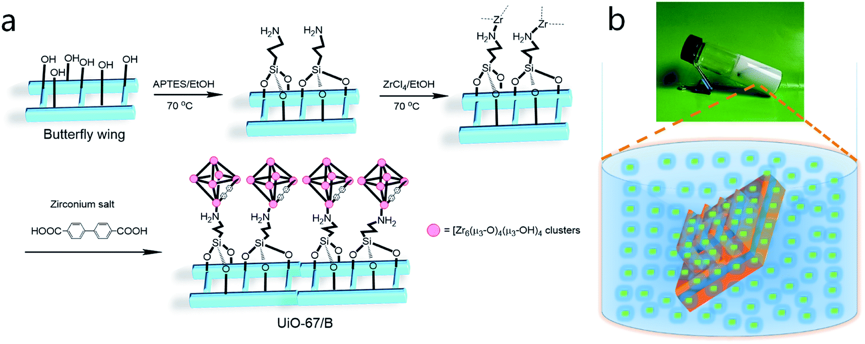 | ||
| Fig. 1 (a) Schematic illustration showing amination and subsequent growth of UiO-67 nanoparticles on the surface of a butterfly wing, and (b) photograph and diagram showing synthesis of UiO-67/B via metal–organic gelation. | ||
The morphologies of the original butterfly wings and the as-prepared composite UiO-67/B were investigated by field-emission scanning electron microscopy (SEM) (Fig. 2). The hierarchical structure of the original butterfly wing was typically of 3D periodicity that comprised parallel ridges and nanoscale ribs, which directly led to the schemochrome, with a space of approximately 600–700 nm between two adjacent main ridges (Fig. 2a and b). Through the gelation synthetic route, the hierarchical structure was topologically replicated by UiO-67 with especially good reproduction of the ridges and ribs (Fig. 2c and d). UiO-67 was anchored uniformly and compactly on the ridges and distributed along the chitin-based ridges. UiO-67/B exhibits a relatively narrow size distribution with an average UiO-67 nanoparticle size of ca. 120–170 nm (Fig. S1†). In comparison, the UiO-67 gel was prepared under the same conditions and SEM shows that the gel consists of smaller nanoparticles with an average diameter of about 50 nm (Fig. S2†). This indicates that the UiO-67 nanoparticles grew larger on the butterfly wing template. FT-IR analysis of UiO-67/B shows that the intense absorption bands at around 1600 and 1415 cm−1 are associated with the stretching modes of the carboxylate groups, and the absorption bands at around 768 and 654 cm−1 are assigned to Zr–O bonds as longitudinal and transverse modes, respectively (Fig. S3†).9,36,37 The powder X-ray diffraction (PXRD) pattern of UiO-67/B is highly consistent with the simulated one of UiO-67 (Fig. 2e), indicating good crystallinity. Lower angles of d111 (5.7°) and d200 (6.5°) reflections for UiO-67/B agreeing well with ones for UiO-67![[thin space (1/6-em)]](https://www.rsc.org/images/entities/char_2009.gif) 9 indicate that the employment of bio-template butterfly wing can lead to perfect crystallographic structure of UiO-67. The results show that UiO-67 nanoparticles were stacked along the specified Zr sites on the butterfly wing template to result in an ordered and regular arrangement 2D layered UiO-67 structure.38 Obviously, the MOG method restricts the sedimentation of UiO-67 nanoparticles, limiting and promoting the formation of uniform UiO-67 nanoparticles on the targeted sites of the butterfly wing template.
9 indicate that the employment of bio-template butterfly wing can lead to perfect crystallographic structure of UiO-67. The results show that UiO-67 nanoparticles were stacked along the specified Zr sites on the butterfly wing template to result in an ordered and regular arrangement 2D layered UiO-67 structure.38 Obviously, the MOG method restricts the sedimentation of UiO-67 nanoparticles, limiting and promoting the formation of uniform UiO-67 nanoparticles on the targeted sites of the butterfly wing template.
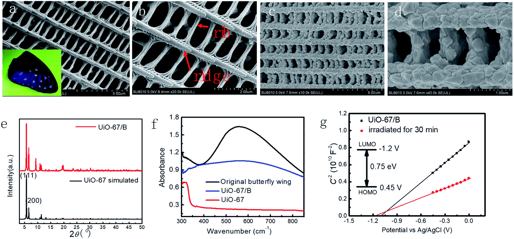 | ||
| Fig. 2 (a and b) SEM images of original butterfly wings (inset shows an optical photograph), and (c and d) SEM images of UiO-67/B (butterfly wing covered by UiO-67). (e) PXRD patterns and (f) UV-visible absorption spectra of UiO-67/B and UiO-67. (g) Mott–Schottky plot of UiO-67/B measured in 0.5 mol L−1 H2SO4 aqueous solution. | ||
Thermogravimetric analysis and differential scanning calorimetry show that there are two main weight loss events (Fig. S4†). The continuous weight loss below 450 °C is mainly attributed to the endothermic degradation of the original butterfly wings.39 The second weight loss from 520 to 550 °C is ascribed to the volatilization of the linker of UiO-67.40
The solid-state ultraviolet-visible diffuse reflectance spectrum of UiO-67/B is depicted in Fig. 2f. UiO-67 exhibits an intense absorption maximum at 340 nm, which is consistent with previous reports.41 While UiO-67/B shows a broad range of absorption across the whole visible region from 380 nm to 780 nm. This demonstrates that the 3D photonic crystal structure may enhance the absorption between wavelengths of 500 and 800 nm, because the original butterfly wing has a broad adsorption in this region. In addition, the calculated energy gap (Eg) of UiO-67/B (0.75 eV) obviously decreases compared with UiO-67 (3.63 eV) (Fig. S5†),42,43 which is more favourable for electron transfer in UiO-67/B. Therefore, Eg may be effectively lowered by using the photonic crystal template via the MOG method.
The Mott–Schottky plot of UiO-67/B was measured at a frequency of 5 kHz. As shown in Fig. 2g, the positive slope is consistent with that of typical n-type semiconductors. The flat band position (Vfb) determined from the Mott–Schottky plot is approximately −1.1 V vs. Ag/AgCl for UiO-67/B. The conduction band (LUMO) of UiO-67 was estimated to be −1.2 V vs. Ag/AgCl. More importantly, Vfb of UiO-67/B changed in the negative direction upon light irradiation which signified that the electrons in the conduction band were more active for promoting photoelectrocatalytic H2 production.44
The electrocatalytic activity of UiO-67/B was investigated towards the hydrogen evolution reaction (HER). The electrocatalysis reactions were all conducted in 0.5 mol L−1 H2SO4 solution with a scan rate of 50 mV s−1. The representative linear sweep voltammetry (LSV) curves in Fig. 3a indicated that bulk UiO-67 powder exhibited poor HER activity, while the current became much larger for UiO-67/B with the aid of the butterfly wing template. The HER onset potential of UiO-67/B was ∼449 mV versus the reversible hydrogen electrode (RHE), lower than that of UiO-67 (∼586 mV). An overpotential of 690 and 766 mV is required to achieve a current density of 10 mA cm−2 for UiO-67/B and UiO-67, respectively. In addition, the original butterfly wing also presented inferior activity (overpotential of 630 mV at 1 mA cm−2), suggesting a synergetic promotion effect between UiO-67 and the photonic crystal structure.
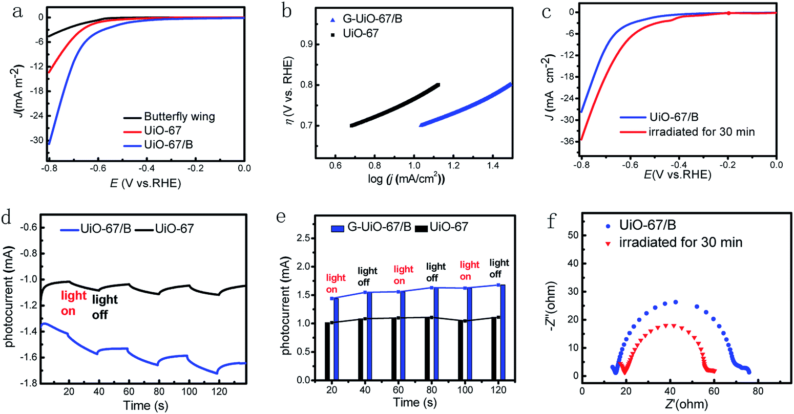 | ||
| Fig. 3 (a) Polarization curves of UiO-67/B, UiO-67 and original butterfly wing. (b) Tafel plots of UiO-67/B and UiO-67. (c) Polarization curves under light irradiation for UiO-67/B. (d) Enlarged photocurrent plots of the first 120 s. (e) Photocurrent variation tendency for UiO-67/B and UiO-67. (f) Transformation of the electrochemical impedance spectra of UiO-67/B under light irradiation for 30 min. | ||
The Tafel slope of UiO-67/B was calculated from polarization curves by the Tafel equation to be 220 mV dec−1, with a larger Tafel slope (∼228 mV dec−1) for UiO-67 (Fig. 3b, Table S1†), revealing higher electrocatalytic activity of UiO-67/B.45 The lower onset potential and the smaller Tafel slope of UiO-67/B than those of UiO-67 demonstrate that the presence of microstructure template in the UiO-67/B film favours proton adsorption kinetics.46
To study the effect produced by light irradiation, UiO-67/B was irradiated continuously by a simulated solar light source (Fig. 3c). UiO-67/B was responsive to light, and an obvious increase in current density was obtained with a certain time of light irradiation. The butterfly wing can capture photoelectrons because of its unique 3D photonic crystal structure which can refract and scatter light. The energy of incident light is greatly reduced so that the generated low-energy photoelectrons can be easily captured; meanwhile, the reflected light is greatly reduced via the 3D hierarchical structure. Thus the incident light can be efficiently absorbed.47,48 This may contribute to the material performance. Regarding UiO-67, the photo-response may benefit from conjugation of an organic linker, resulting in a bathochromic shift in the absorption maxima.49,50 In comparison, UiO-67/B showed an obvious increase in the photocurrent when irradiated for 30 min. The current density remarkably increased from 3.2 to 7.0 mA cm−2 (at −0.6 V vs. RHE) for UiO-67/B.
To unveil the charge-separation efficiency, photocurrent measurements were carried out. The photocurrent for UiO-67/B was enhanced as compared to the pristine UiO-67, revealing that the formation of butterfly wing-MOF Schottky junction helps separate the photogenerated electron–hole pairs (Fig. 3d and e). UiO-67/B exhibited a raised photocurrent of ∼130 μA within the first 20 s of simulated solar irradiation, while the raised photocurrent was ∼67 μA for UiO-67. It is worth noting that the photocurrent variation was almost constant with an increased time of 120 s for UiO-67, while interestingly the photocurrent variation for UiO-67/B gradually increased with light irradiation, and the tendency continued even after the light was removed. This indicates that the photogenerated carriers still existed after the light excitation, and this activation state had a certain lifetime, making an ocean of electrons. As shown in Fig. 3d, the increasing baseline of photocurrent derives from the enrichment of photogenerated electrons produced by the 3D photonic crystal structure. The photogenerated electrons can refract in the 3D photonic crystal structure, so it takes time for them to be quenched.51,52 In short, UiO-67/B displays a much stronger photocurrent response, suggesting a much higher efficiency of photogenerated charge transfer from butterfly wing to UiO-67 nanoparticles in UiO-67/B. According to Fig. 2g, more electrons were generated with an increase of illumination time. The optimized carrier density was increased 2.15 times after 30 min of light irradiation.
Electrochemical impedance spectroscopy (EIS) was used to provide further insight into the activity of UiO-67/B toward the HER, which is used to analyze the interfacial charge transfer process between electrode and electrolyte.50 From Fig. 3f, UiO-67/B exhibited a fitting resistance of ca. 55 Ω, indicative of efficient electron transport and favourable HER kinetics at the electrolyte interface. More interestingly the radius was largely reduced under photoirradiation for 30 min with a fitting resistance of ca. 19 Ω, meaning more efficient separation of photogenerated electron–hole pairs and an effective photoelectrocatalytic performance.53 Obviously, the internal resistance corresponding to the overall charge transfer process under illumination is significantly lower than that under dark conditions.54 The results are consistent with the LSV and photocurrent results. HER stability tests indicate that the activity of UiO-67/B was maintained for at least 12 h when using GCE as working electrode at 0.7 V vs. RHE in 0.5 mol L−1 H2SO4 (Fig. S6†). The stability was monitored by FT-IR showing the overall structure of UiO-67/B was retained over time (Fig. S7†).
On the basis of the above results, possible interface electron transfer behaviour and the corresponding photocatalytic mechanism for H2 production are proposed and illustrated in Fig. 4. Upon visible light irradiation, UiO-67/B not only acts as an effective visible light harvester to trap photogenerated charge, but also can inhibit the recombination of photoinduced electron–hole pairs and prolong the lifetime of photoinduced charge carriers. Since the band gap of UiO-67/B is lower (0.75 eV), the photoinduced electrons of UiO-67/B can transfer to the Zr6-oxo cluster faster through the LMCT process. UiO-67/B film covered with uniform UiO-67 nanoparticles (120–170 nm) is favourable for HER kinetics, which is consistent with the Tafel plot. The electrons at the Zr6-oxo cluster can reduce adsorbed H+ to evolve H2 in photocatalytic H2 production.39
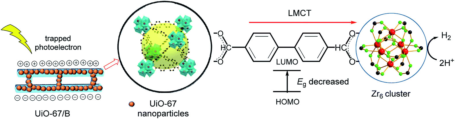 | ||
| Fig. 4 Proposed mechanism of photoelectrocatalytic H2 production over UiO-67/B under visible light. | ||
Conclusions
In summary, UiO-67 nanoparticles have been anchored on butterfly wings which are employed as an efficient bio-photonic crystal support to obtain activated catalysts of UiO-67/B for the HER. MOG is employed for delineating and reproducing the photonic crystal structure of the butterfly wing. UiO-67/B obtained via MOG possesses a lower band gap (0.75 eV). UiO-67/B promotes more photogenerated electron transfer through the LMCT process. In addition, UiO-67/B exhibits remarkable electrochemical HER activity with a Tafel slope of 220 mV dec−1 and a lower onset potential of nearly 449 mV than UiO-67 (Tafel slope, 228 mV dec−1; onset potential, 586 mV). The special photo-response of UiO-67/B is indicated by an increase of current density from 28 mA cm−2 to 36 mA cm−2 at −0.6 V (vs. RHE) with light irradiation within 30 min. The MOG route allows retention of the fine structure from the butterfly wing template, subsequently depositing MOF nanoparticles with narrow particle size distribution. As a result, the photoelectrocatalytic performance is improved which implies new opportunities for MOF-based composites in various applications.Experimental
Materials and methods
Fresh butterfly wings were pretreated by a softening process in steam and afterwards air-dried. To fabricate UiO-67/B, butterfly wings were first immersed in dilute 8 vol% nitric acid for 5 h, washed with deionized water and dried in air. Then APTES diluted with absolute ethanol (volume fraction 20%, purchased from Damao Chemical Reagent Factory, Tianjin, China, ≥99.0%) was used to activate the butterfly wings at 70 °C for 5 h, followed by washing with ethanol.52 The surface-aminated butterfly wing was then soaked in absolute ethyl alcohol saturated with ZrCl4 (from Aladdin Shanghai, China, ≥98%) for 5 h at 70 °C, rinsed in absolute ethanol, and air-dried. UiO-67 was generated on the surface of the Zr4+ coordinated chitin-based wing scale by means of hydrothermal synthesis and gelation.55 SEM was performed using an ultra-high-resolution SU8010 FE-SEM (Hitachi Instruments, working voltage 5 kV, working current 5 mA). Samples were treated via Au sputtering before observation. PXRD was conducted with a Rigaku Smart Lab X-ray diffractometer (Bragg–Brentano geometry, Cu-Kα1 radiation, λ = 1.54056 Å, working voltage 40 kV, working current 15 mA). Measurements were made over a range of 2° < 2θ < 50° in 0.05° step size at a scanning rate of 5 deg per min. Infrared spectra were recorded using a PerkinElmer Fourier transform infrared spectrometer, and the spectra were obtained in the range of 4000–500 cm−1 for 32 scans using attenuated total reflection accessories. UV-visible absorption spectra were obtained with a Shimadzu UV-2450 spectrometer with measurement range from 200 to 850 nm.UiO-67/B
The synthesis of UiO-67/B through a gel path was performed in a 45 mL bottle by dissolving 4.35 mmol (351 mg) 4,4-biphenyldicarboxylic acid and 3 mmol (332 mg) ZrOCl2·8H2O in 18 mL DMF, after which 450 μL of a 37 wt% HCl solution and 600 μL glacial acetic acid were added. The modified butterfly wing was carefully immersed into the mixture and the resulting mixture was placed at 100 °C for 3 h. After aging at 100 °C for 5 h, UiO-67/B was taken out for solvent exchange with DMF (30 mL × 2) and EtOH (20 mL × 2) in sequence.UiO-67
The gel was prepared by a modified literature method.35 4,4-Biphenyldicarboxylic acid (351 mg, 1.45 mmol) and ZrOCl2·8H2O (322 mg, 1.00 mmol) in 6 mL DMF were dissolved in a 15 mL capped bottle, and 150 μL of 37 wt% HCl solution and 200 μL glacial acetic acid were added. The resulting mixture was placed at 100 °C overnight. The resulting white opaque gel was cooled to room temperature for solvent exchange with DMF (10 mL × 2) and EtOH (10 mL × 2) in sequence.Electrochemical measurement
All the electrocatalytic properties were measured with a three-electrode system (CHI660E), which included an Ag/AgCl reference electrode, a carbon rod counter electrode, and fluorine-doped tin oxide (FTO) glass as a working electrode. The working electrode was prepared as follows: 1 mg of UiO-67 powder and 300 μL of 2:1 (v/v) ethanol–Nafion (0.5 wt%) were homogeneously mixed under sonication for 10 min. Then, 20 μL of the ink was drop-cast onto FTO (0.5 cm × 0.5 cm) to obtain a catalyst loading of 0.067 mg cm−2, followed by dropping 3 μL of 0.05 wt% Nafion for protection. UiO-67/B (0.2 mg, 0.5 cm × 0.5 cm) was clipped and attached to the surface of FTO with 0.5 wt% Nafion. LSV polarization curves were obtained in 0.5 mol L−1 H2SO4 at a scan rate of 50 mV s−1. EIS was conducted in the same configuration at an overpotential of −0.6 V vs. RHE within the frequency range of 105–0.1 Hz with a perturbation voltage amplitude of 5 mV. The Mott–Schottky plots for the samples were obtained at a frequency of 5.0 kHz. The photocurrent of the samples was measured under irradiation from a 350 W xenon lamp (PLS-SXE300D) (light on/off cycle, 20 s) with an average intensity of 100 mW cm−2. All the results were calibrated with respect to the RHE using E(RHE) = E(Ag/AgCl) + 0.197 V.
Conflicts of interest
There are no conflicts to declare.Acknowledgements
We gratefully acknowledge the NSFC (51573216) and the NSF of Guangdong Province (2019A1515010710) for financial support.Notes and references
- X. Zhang, W. Gao, X. Su, F. Wang, B. Liu, J.-J. Wang, H. Liu and Y. Sang, Nano Energy, 2018, 48, 481–488 CrossRef CAS.
- D. Gust, T. A. Moore and A. L. Moore, Acc. Chem. Res., 2009, 42, 1890–1898 CrossRef CAS PubMed.
- B. Zhang and L. Sun, Chem. Soc. Rev., 2019, 48, 2216–2264 RSC.
- J. Yang, D. Wang, H. Han and C. Li, Acc. Chem. Res., 2013, 46, 1900–1909 CrossRef CAS PubMed.
- S.-N. Zhao, X.-Z. Song, S.-Y. Song and H.-j. Zhang, Coord. Chem. Rev., 2017, 337, 80–96 CrossRef CAS.
- M. Kandiah, M. H. Nilsen, S. Usseglio, S. Jakobsen, U. Olsbye, M. Tilset, C. Larabi, E. A. Quadrelli, F. Bonino and K. P. Lillerud, Chem. Mater., 2010, 22, 6632–6640 CrossRef CAS.
- B. Wang, X.-L. Lv, D. Feng, L.-H. Xie, J. Zhang, M. Li, Y. Xie, J.-R. Li and H.-C. Zhou, J. Am. Chem. Soc., 2016, 138, 6204–6216 CrossRef CAS PubMed.
- H.-L. Jiang, D. Feng, K. Wang, Z.-Y. Gu, Z. Wei, Y.-P. Chen and H.-C. Zhou, J. Am. Chem. Soc., 2013, 135, 13934–13938 CrossRef CAS PubMed.
- J. H. Cavka, S. Jakobsen, U. Olsbye, N. Guillou, C. Lamberti, S. Bordiga and K. P. Lillerud, J. Am. Chem. Soc., 2008, 130, 13850–13851 CrossRef PubMed.
- L. Shen, H. B. Wu, F. Liu, J. L. Brosmer, G. Shen, X. Wang, J. I. Zink, Q. Xiao, M. Cai, G. Wang, Y. Lu and B. Dunn, Adv. Mater., 2018, 30, 1707476 CrossRef PubMed.
- G. Zhong, D. Liu and J. Zhang, ChemistrySelect, 2018, 3, 7066–7080 CrossRef CAS.
- R. Malik, M. J. Loveridge, L. J. Williams, Q. Huang, G. West, P. R. Shearing, R. Bhagat and R. I. Walton, Chem. Mater., 2019, 31, 4156–4165 CrossRef CAS.
- Z.-M. Zhang, T. Zhang, C. Wang, Z. Lin, L.-S. Long and W. Lin, J. Am. Chem. Soc., 2015, 137, 3197–3200 CrossRef CAS PubMed.
- M. B. Chambers, X. Wang, N. Elgrishi, C. H. Hendon, A. Walsh, J. Bonnefoy, J. Canivet, E. A. Quadrelli, D. Farrusseng, C. Mellot-Draznieks and M. Fontecave, ChemSusChem, 2015, 8, 603–608 CrossRef CAS PubMed.
- C. Wang, Z. Xie, K. E. deKrafft and W. Lin, J. Am. Chem. Soc., 2011, 133, 13445–13454 CrossRef CAS PubMed.
- W.-M. Liao, J.-H. Zhang, Z. Wang, S.-Y. Yin, M. Pan, H.-P. Wang and C.-Y. Su, J. Mater. Chem. A, 2018, 6, 11337–11345 RSC.
- K. M. Choi, D. Kim, B. Rungtaweevoranit, C. A. Trickett, J. T. D. Barmanbek, A. S. Alshammari, P. Yang and O. M. Yaghi, J. Am. Chem. Soc., 2017, 139, 356–362 CrossRef CAS PubMed.
- C.-C. Hou, T.-T. Li, S. Cao, Y. Chen and W.-F. Fu, J. Mater. Chem. A, 2015, 3, 10386–10394 RSC.
- M. Usman, S. Mendiratta and K.-L. Lu, Adv. Mater., 2017, 29, 1605071 CrossRef PubMed.
- Y. Chen, D. Wang, X. Deng and Z. Li, Catal. Sci. Technol., 2017, 7, 4893–4904 RSC.
- M. A. Nasalevich, M. van der Veen, F. Kapteijn and J. Gascon, CrystEngComm, 2014, 16, 4919–4926 RSC.
- T. Zhang and W. Lin, Chem. Soc. Rev., 2014, 43, 5982–5993 RSC.
- A. Dhakshinamoorthy, M. A. Abdullah and H. García, Angew. Chem., Int. Ed., 2016, 55, 5414–5445 CrossRef CAS PubMed.
- C. G. Silva, I. Luz, F. X. L. i. Xamena, A. Corma and H. García, Chem.–Eur. J., 2010, 16, 11133–11138 CrossRef CAS PubMed.
- V. Saranathan, C. O. Osuji, S. G. J. Mochrie, H. Noh, S. Narayanan, A. Sandy, E. R. Dufresne and R. O. Prum, Proc. Natl. Acad. Sci. U. S. A., 2010, 107, 11676–11681 CrossRef CAS PubMed.
- R. H. Siddique, Y. J. Donie, G. Gomard, S. Yalamanchili, T. Merdzhanova, U. Lemmer and H. Hölscher, Sci. Adv., 2017, 3, e1700232 CrossRef PubMed.
- J. Liu, H. Zhao, M. Wu, B. Van der Schueren, Y. Li, O. Deparis, J. Ye, G. A. Ozin, T. Hasan and B.-L. Su, Adv. Mater., 2017, 29, 1605349 CrossRef PubMed.
- S. Lou, X. Guo, T. Fan and D. Zhang, Energy Environ. Sci., 2012, 5, 9195–9216 RSC.
- Q. Zhao, T. Fan, J. Ding, D. Zhang, Q. Guo and M. Kamada, Carbon, 2011, 49, 877–883 CrossRef CAS.
- W. Zhang, D. Zhang, T. Fan, J. Gu, J. Ding, H. Wang, Q. Guo and H. Ogawa, Chem. Mater., 2009, 21, 33–40 CrossRef.
- X.-H. Li and M. Antonietti, Chem. Soc. Rev., 2013, 42, 6593–6604 RSC.
- L. Liu, J. Zhang, H. Fang, L. Chen and C.-Y. Su, Chem.–Asian J., 2016, 11, 2278–2283 CrossRef CAS PubMed.
- X. Feng, L. Zeng, D. Zou, Z. Zhang, G. Zhong, S. Peng, L. Liu, L. Chen and J. Zhang, RSC Adv., 2017, 7, 37194–37199 RSC.
- J. Santos-Lorenzo, R. S. José-Velado, J. Albo, G. Beobide, P. Castaño, O. Castillo, A. Luque and S. Pérez-Yáñez, Microporous Mesoporous Mater., 2019, 284, 128–132 CrossRef CAS.
- B. Bueken, N. V. Velthoven, T. Willhammar, T. Stassin, I. Stassen, D. A. Keen, G. V. Baron, J. F. M. Denayer, R. Ameloot, S. Bals, D. D. Vos and T. D. Bennett, Chem. Sci., 2017, 8, 3939–3948 RSC.
- H. Fei and S. M. Cohen, Chem. Commun., 2014, 50, 4810–4812 RSC.
- W. Peng, S. Zhu, W. Wang, W. Zhang, J. Gu, X. Hu, D. Zhang and Z. Chen, Adv. Funct. Mater., 2012, 22, 2072–2080 CrossRef CAS.
- J. Duan, S. Chen and C. Zhao, Nat. Commun., 2017, 8, 15341 CrossRef CAS PubMed.
- Y. Tan, J. Gu, X. Zang, W. Xu, K. Shi, L. Xu and D. Zhang, Angew. Chem., 2011, 123, 8457–8461 CrossRef.
- M. J. Katz, Z. J. Brown, Y. J. Colon, P. W. Siu, K. A. Scheidt, R. Q. Snurr, J. T. Hupp and O. K. Farha, Chem. Commun., 2013, 49, 9449–9451 RSC.
- S. Chavan, J. G. Vitillo, D. Gianolio, O. Zavorotynska, B. Civalleri, S. Jakobsen, M. H. Nilsen, L. Valenzano, C. Lamberti, K. P. Lillerud and S. Bordiga, Phys. Chem. Chem. Phys., 2012, 14, 1614–1626 RSC.
- W. A. Maza, A. J. Haring, S. R. Ahrenholtz, C. C. Epley, S. Y. Lin and A. J. Morris, Chem. Sci., 2016, 7, 719–727 RSC.
- L.-M. Yang, E. Ganz, S. Svelle and M. Tilset, J. Mater. Chem. C, 2014, 2, 7111–7125 RSC.
- J. He, J. Wang, Y. Chen, J. Zhang, D. Duan, Y. Wang and Z. Yan, Chem. Commun., 2014, 50, 7063–7066 RSC.
- L. F. Pan, Y. H. Li, S. Yang, P. F. Liu, M. Q. Yu and H. G. Yang, Chem. Commun., 2014, 50, 13135–13137 RSC.
- W. F. Chen, K. Sasaki, C. Ma, I. F. Anatoly, N. Marinkovic, T. M. James, Y. Zhu and R. A. Radoslav, Angew. Chem., Int. Ed., 2012, 51, 6131–6135 CrossRef CAS PubMed.
- W. Niu, L. T. Su, R. Chen, H. Chen, Y. Wang, A. Palaniappan, H. Sun and A. Y. Tok, Nanoscale, 2014, 6, 817–824 RSC.
- P. Mahato, A. Monguzzi, N. Yanai, T. Yamada and N. Kimizuka, Nat. Mater., 2015, 14, 924–930 CrossRef CAS PubMed.
- S. Chavan, J. G. Vitillo, M. J. Uddin, F. Bonino, C. Lamberti, E. Groppo, K.-P. Lillerud and S. Bordiga, Chem. Mater., 2010, 22, 4602–4611 CrossRef CAS.
- X. Zhao, T. Xu, W. Yao, C. Zhang and Y. Zhu, Appl. Catal., B, 2007, 72, 92–97 CrossRef CAS.
- C. Kang, S. Lee, S. Choe, Y. Lee, C.-L. Lee and B. Lee, Opt. Express, 2013, 21, 23391–23400 CrossRef CAS PubMed.
- P. N. Ciesielski, C. J. Faulkner, M. T. Irwin, J. M. Gregory, N. H. Tolk, D. E. Cliffel and G. K. Jennings, Adv. Funct. Mater., 2010, 20, 4048–4054 CrossRef CAS.
- H. Liu, S. Cheng, M. Wu, H. Wu, J. Zhang, W. Li and C. Cao, J. Phys. Chem. A, 2000, 104, 7016–7020 CrossRef CAS.
- T. Lopes, L. Andrade, H. A. Ribeiro and A. Mendes, Int. J. Hydrogen Energy, 2010, 35, 11601–11608 CrossRef CAS.
- X. Yang, A. Wolcott, G. Wang, A. Sobo, R. C. Fitzmorris, F. Qian, J. Z. Zhang and Y. Li, Nano Lett., 2009, 9, 2331–2336 CrossRef CAS PubMed.
Footnote |
| † Electronic supplementary information (ESI) available: Additional spectra and electrocatalytic data. See DOI: 10.1039/d0ra00868k |
| This journal is © The Royal Society of Chemistry 2020 |