
 Open Access Article
 This Open Access Article is licensed under a Creative Commons Attribution-Non Commercial 3.0 Unported Licence
Enhanced gas sensing performance of perovskite YFe1−xMnxO3 by doping manganese ions†
Aerzigu Xukeer a,
Zhaofeng Wu*a,
Qihua Suna,
Furu Zhongb,
Min Zhanga,
Mengqiu Long*c and
Haiming Duan*a
a,
Zhaofeng Wu*a,
Qihua Suna,
Furu Zhongb,
Min Zhanga,
Mengqiu Long*c and
Haiming Duan*a
aSchool of Physics Science and Technology, Xinjiang University, Urumqi, Xinjiang 830046, P. R. China. E-mail: wuzf@xju.edu.cn; dhm@xju.edu.cn
bSchool of Physics and Electronic Science, Zunyi Normal College, Zunyi, 563006, Guizhou, P. R. China
cInstitute of Super-microstructure and Ultrafast Process in Advanced Materials, School of Physics and Electronics, Central South University, Changsha 410083, P. R. China
First published on 17th August 2020
Abstract
Perovskite YFe1−xMnxO3 with a hierarchical structure were prepared by a simple hydrothermal method and used as gas sensing materials. The structure, morphology and composition of YFe1−xMnxO3 were investigated using X-ray diffraction, transmission electron microscopy, scanning electron microscopy and X-ray photoelectron spectroscopy. The gas sensing test showed that all YFe1−xMnxO3 perovskites with different Mn doping concentrations displayed fast response and recovery characteristics to multiple analytes as well as good stability and recoverability. With the increase of Mn doping concentration, the response of YFe1−xMnxO3 to four kinds of target atmospheres first increases, then decreases. The sensing performance of YFe1−xMnxO3 is best when x = 0.05. Compared with pure YFeO3, the responses of YFe0.95Mn0.05O3 to 1000 ppm of CH2O, C2H6O, H2O2 and 100% relative humidity were increased by 835%, 1462%, 812% and 801%, respectively. The theoretical detection limit of YFe0.95Mn0.05O3 for H2O2 and CH2O is 1.75 and 2.55 ppb, respectively. Furthermore, the possibility of buildings a sensor array based on YFe1−xMnxO3 with different doping concentrations was evaluated by principal component analysis and radar chart analysis. It is feasible to realize the visual and discriminative detection of the target analyte by constructing sensor arrays through radar chart analysis and database construction.
1. Introduction
Perovskites have a great effect in many domains, such as gas sensors.1–4 Recently, a variety of perovskite structures based on ABO3-type composites have been used as gas sensors due to their high stability and also their characteristics of sensitivity and selectivity.4–6 Perovskite BaSnO3 obtained from a simple wet chemical route was calcined at different temperatures and the gas sensing performance was studied in the presence of O2, CO and NO2 as a function of the temperature. The BaSnO3 sensor shows a maximum sensitivity to O2 and at 700 °C, to CO and NO2 at 600 °C, respectively.7 Traversa fabricated the thick films of LaFeO3 and SmFeO3 by screen-printing technology on alumina substrates with comb-type Au electrodes. The effect of temperature and humidity on the gas sensing performance of LaFeO3 and SmFeO3 to NO2 and CO were studied and the presence of humidity does not affect the detection of NO2 and CO.8 The sensing properties of SrTiO3 were regulated by the annealing temperature due to the change of the grain size of SrTiO3. The optimal relative resistance (Rnitrogen/R20% oxygen) value of 6.35 is obtained for the synthesized SrTiO3 sample annealed at 400 °C and operating at 40 °C, which is much lower than that for the conventional metal oxide semiconducting oxygen gas sensors (300–500 °C).9,10 Later, traditional metal oxide semiconductors or noble metal nanoparticles were used to form composites with perovskite materials to improve their gas sensing performance. Ruan synthesized porous core–shell PrFeO3/α-Fe2O3 composites, realized a high gas response, low optimum operating temperature and superior selectivity to ethyl acetate gas. The response (Rair/Rgas) of the sensor based on PrFeO3/α-Fe2O3 is 22.85 toward 100 ppm ethyl acetate at 206 °C, about 3 times higher than that of pristine α-Fe2O3 sensor. Besides, the sensor possesses a rapid response and recovery speed of 8 s and 9 s for detecting 100 ppm ethyl acetate.2 Perovskite LaCoO3 was synthesized by sol–gel method and functionalized by Ag nanoparticles. An improved sensitivity and selectivity to H2S was observed for Ag/LaCoO3 sensors, compared with pure LaCoO3 sensor. The role of Ag nanoparticles in the selective sensitivity of Ag/LaCoO3 composites to H2S gas were unveiled using in situ infrared spectroscopy.3 Mandayo prepared BaTiO3–CuO films and annealed at different temperatures in order to test their electrical behavior by means of impedance measurements under different CO2 concentrations (0–2000 ppm). Pt and Ag are tested as electrode materials and the influence of Ag as surface and multilayer additive for sensing response enhancement is also studied.11Compared with the composite method of improving the sensing performance of the perovskites, doping may be a simpler and more effective way to regulate the sensing properties of perovskites, which can be done synchronously in the process of synthesizing materials.12,13 The cubic ABO3 unit cell of perovskites contain a large 12-coordinated A cation centered between the corner-sharing BO6 octahedra. The ABO3 structure is favorable for cation substitution in either A, or B positions, which influences the electrophysical and chemical properties of the perovskite oxides. This means that the controlled doping of ABO3 structure can effectively control the gas sensing properties of perovskites. Rothschild explored the sensing performances of SrTi1−xFexO3−δ as oxygen sensors in lean burn engines and found that with the change of the molar ratio of Ti/Fe, the bandgap energy and gas sensing performance of the SrTi1−xFexO3−δ material changed synchronously.14 Among these perovskites, yttrium orthoferrite (YFeO3) has attracted the attention of researchers due to their excellent magnetic, magneto-optical, physical and chemical properties originated by their ionic and electronic defects as well as structure distortions.15–17 To the best of our knowledge, most previous studies on YFeO3 have been focused on its photoluminescence, catalysts and magnetic properties,18–22 but few have been reported on gas sensing. In terms of actual sensing requirements, controlling and monitoring the toxic, inflammable and explosive gases, such as formaldehyde (CH2O), ethanol (C2H6O) and hydrogen peroxide (H2O2), is important for industrial production, indoor life and public safety.13,23–25
Doping can change the composition, carrier density and surface states of sensing materials, which is an effective strategy to regulate the structure and the gas-sensitive properties, as well as an important means to study the gas-sensitive mechanism of semiconductor materials.26,27 In our work, the hierarchical YFe1−xMnxO3 was prepared by hydrothermal method and the substitution of Mn ions at Fe site was achieved, because of the close ionic radius of Mn3+ (0.580 Å), Mn2+ (0.670 Å) and Fe3+ (0.645 Å).28,29 The effect of Mn doping on the gas sensing performances of YFe1−xMnxO3 to CH2O, C2H6O and H2O2 has been studied. Furthermore, the possibility of building sensor array based on YFe1−xMnxO3 with different doping concentration was evaluated by principal component analysis (PCA) and radar chart analysis.
2. Experimental section
2.1 Material preparation
Yttrium nitrate hexahydrate [Y(NO3)3·6H2O], iron(III) nitrate nonahydrate [Fe(NO3)3·9H2O], manganese(II) chloride (MnCl2·4H2O), and potassium hydroxide (KOH) are analytical reagents, purchased from Sinopharm Chemical Reagent Co., Ltd. YFe1−xMnxO3 (x = 0, 0.025, 0.05, 0.075 and 0.1) nano-powders were prepared by hydro-thermal method. First, 0.01 mol of Y(NO3)3·6H2O and Fe(NO3)3·9H2O, and a certain amount of MnCl2·4H2O were weighed and dissolved in 30 ml of distilled water with stirring. Second, 0.75 mol of KOH as mineralizing agent was directly added into the above solution, the mixtures were then transferred to Teflon-lined stainless steel autoclave and heated at 230 °C for 72 h. Third, the dark products were filtered and washed several times with distilled water to obtain crystals that are then dried in air.2.2 Device fabrication and testing
The fabrication and testing of sensors are the same as the previous reports.13,25 Specifically, sensors based on YFe1−xMnxO3 (x = 0, 0.025, 0.05, 0.075 and 0.1) were fabricated by coating the paste of YFe1−xMnxO3 on a ceramic substrate by a thin brush to form a sensing film on which silver interdigitated electrodes with both finger-width and inter finger spacing of about 200 μm was previously printed. The sensors based on YFe1−xMnxO3 (x = 0, 0.025, 0.05, 0.075 and 0.1) were defined as S1, S2, S3, S4 and S5, respectively. The sensor were dried at 25 °C about 24 h and then aged at 3 V in air for about 48 h to ensure the good stability. Gas sensing performance was measured by an electrochemical workstation (CIMPS-2, ZAHER ENNIUM) in a 25 °C test room controlled by air conditioning system. For the target vapor of different concentrations is prepared according to formula (1):
 | (1) |
2.3 Characterization
X-ray powder diffraction (XRD) measurement was carried out using powder XRD (Bruker D8 Advance, with Cu-Kα radiation operating at 40 kV and 40 mA). Field emission scanning electron microscopy (FE-SEM, S-4800, Hitachi, Japan) was used to investigate the surface morphology of YFe1−xMnxO3 (x = 0.000, 0.025, 0.050, 0.075 and 0.100). Transmission Electron Microscopy (TEM, FEI Tecnai G2 F20 S-TWIN) was used to characterize the morphology of YFe1−xMnxO3 (x = 0.050) sample. The surface elements and chemical states of the samples were examined using X-ray photoelectron spectroscopy (XPS, PHI 5000Versa Probe). The content of each element in the materials was measured by energy dispersive X-ray spectroscopy (EDS) and inductively coupled plasma emission spectrometer (ICP).3. Results and discussion
3.1 Morphology and structural properties
The surface morphologies of YFe1−xMnxO3 (x = 0.000, 0.025, 0.050, 0.075 and 0.100) investigated by SEM are given in Fig. 1. On the macro level, all the micron particles of YFe1−xMnxO3 are basically composed of a square sheet and two sides of the square sheet symmetrically growing hierarchical structures (Fig. 1a, d, g, j, m). At the micro level, the hierarchical structure on both sides of the square sheet is like a maze of long building units (Fig. 1b, e, h, k, n), and their morphology does not change with the increase of Mn doping. More detailed observation shows that the basic unit is a quadrangular prism with width of several hundred nanometers, length of several microns or even more than ten microns. One-dimensional structure of YFe1−xMnxO3 facilitates the rapid transport and transfer of charges between one-dimensional quadrangle and target gas.30,31 Moreover, there are some nanoparticles growing on the surface of the prism (Fig. 1c, f, i, l, o). This may provide a large surface area and active sites for the adsorption of the target gas, which is conducive to improving the gas sensing performance of the material.32 In addition, it should be noted that when the doping amount of manganese ion reaches 10%, the hierarchical structure becomes less fine and the basic unit becomes wider, changing slightly the morphology of the YFe1−xMnxO3 materials. | ||
| Fig. 1 SEM images of five samples (a–c) YFeO3, (d–f) YFe0.975Mn0.025O3, (g–i) YFe0.95Mn0.05O3, (j–l) YFe0.925Mn0.075O3, and (m–o) YFe0.9Mn0.1O3. | ||
XRD patterns of five YFe1−xMnxO3 doped with different amount of Mn are shown in Fig. 2a. The XRD investigation suggests that all these samples give rise to well-established peaks of orthorhombic perovskite structure with lattice constant a = 5.5957 Å, b = 7.6046 Å and c = 5.2819 Å (JCPDS no. 89-2609).28,33,34 As shown in Fig. 2a, the typical diffraction peaks at 25.99, 31.98, 33.17, 33.94, 39.54, 47.31, 47.87, 48.91, 53.45, 57.73, 58.75, 60.24 and 76.017 can be ascribed to the (111), (200), (121), (002), (112), (202), (040), (212), (311), (321), (240) and (123) faces of orthorhombic YFeO3, which are comparable to those reported in literature.28,33,34 In the concentration range of 10%, with the increase of Mn doping concentration, the structure and crystal phase of YFe1−xMnxO3 materials have almost no change, and the pure YFeO3 structure is still maintained. It should be pointed out that the intensity of the diffraction peak gradually weakens with the increase of Mn ions in YFe1−xMnxO3, especially when the doping amount of Mn ions reaches 10% (S5). This is due to the structural disorder caused by the difference of radius between Mn and Fe ions. The lattice parameters according to the XRD are plotted against Mn concentration (x) as shown in Fig. S1.† The parameter a increases whereas b and c parameters decrease with the increase of Mn concentration, which is consistent with those reported in literatures.20,28 The increase in the parameter a with the increase of Mn concentration (x) indicates the presence of Jahn–Teller distortion associated with Mn3+ ions.
 | ||
| Fig. 2 (a) XRD patterns, (b) HRTEM images, (c) content of Mn element in YFe1−xMnxO3 according to EDS test, and (d) EDS mappings of the samples. | ||
To further explore the structure of YFe1−xMnxO3, HRTEM study was carried out, as presented in Fig. 2b. The (200), (022) and (221) planes of YFeO3 is observed, which show the indistinct lattice fringe of 0.264, 0.224 and 0.186 nm space, respectively. The content of Mn element in YFe1−xMnxO3 was determined by energy dispersive spectroscopy (EDS) and increased significantly with the increase of the ratio of Mn/Fe in the precursor, achieving 3.26%, 5.95%, 12.60% and 14.10% (Fig. 2c) for the S2, S3, S4 and S5, respectively. It is worth pointing out that the experimental values of Mn content are higher than the theoretical values, which may be caused by the tendency of Mn doping to migrate to the surface of the material. In addition, EDS mappings of the YFe1−xMnxO3 showed strong and uniform signals of Mn, Fe, Y and O, as seen in Fig. 2d, and the original SEM image selected for the EDS mapping was shown in Fig. S2.† This shows that Mn ions are evenly distributed on the surface of YFe1−xMnxO3.
Fig. S3a† shows the UV-vis spectra of the YFe1−xMnxO3 materials. It is interesting to observe that the UV reflection intensity of YFe1−xMnxO3 from 250 nm to 400 nm decreased gradually with the increase of Mn doping, which means that their absorption of ultraviolet region is gradually strengthened. The UV absorption band can be primarily ascribed to electrons promotion of YFe1−xMnxO3 from the valence band to the conduction band.35 In contrast to the pure YFeO3 powder, the absorption edge of the YFe1−xMnxO3 samples displays different shifts to the visible region. This has been confirmed by roughly estimating the band gap of samples according to the plot in Fig. 3b, which is obtained via the transformation based on the Kubelka–Munk function. The estimated band gap values of S1, S2, S3, S4 and S5 are approximately 2.40, 2.35, 2.30, 2.20 and 2.02 eV, respectively, clearly showing the narrowing band gaps as compared to the estimated 2.40 eV of the pure YFeO3. A smaller band gap means that electrons in the valence band can more easily transition to the conduction band, increasing the carrier concentration. The change of carrier concentration has an important effect on gas sensitive performance of the sensing material. Therefore, it can be concluded that Mn doping has an important effect on the gas sensitive performance of YFe1−xMnxO3.
 | ||
| Fig. 3 XPS peaks and the Gaussian fitting peaks of (a) Fe 2p, (b) Mn 2p, (c) O 1s for YFe0.95Mn0.05O3 (x = 0.05) powder. | ||
As shown in Fig. 3a, Fe element doped in YFe0.95Mn0.05O3 exists in mixed valence state, the Fe 2p3/2 peaks at 710.5 and 712.5 eV could be assigned to Fe2+ and Fe3+ ions, respectively.18,36 As shown in Fig. 3b, the Mn 2p region consists of a spin–orbit doublet of Mn 2p3/2 and Mn 2p1/2, and the Mn ions doped in YFe0.95Mn0.05O3 also exist in mixed valence state. The peaks of the Mn elements located at 640.7 and 642.5 eV correspond to Mn2+ and Mn3+ ions, respectively. These results are in good agreement with reports in the literature.12,37 Because of the presence of Fe3+ ions, a small amount of oxygen in the reactor and the high temperature and pressure generated during the reaction (230 °C for 72 h), the oxidation of Mn2+ ions will be promoted to a certain extent to produce Mn3+ ions. The O 1s peak data for YFe0.95Mn0.05O3 are presented in Fig. 3c, indicating an asymmetric peak that is usually fitted with three components. The fitted peaks located at 529.9, 531.5 and 532.7 eV were labeled as OL, OV and OC, respectively. OL, OV and OC was associated with lattice oxygen, oxygen vacancy, and adsorbed oxygen, respectively.38,39 For other samples, the XPS peaks of Mn, Fe with different valence states and three kinds of oxygen, and their fitting peaks are shown in Fig. S4, S5 and S6,† respectively.
The proportion of two kinds of Mn ions and oxygens is calculated according to their corresponding peak area and listed in the Table 1. It is worth noting that with the increase of doping amount of Mn ions in YFe1−xMnxO3, the proportion of Mn2+ ion decreases, and the proportion of Mn3+ ions increases. However, the increase of Mn ions in YFe1−xMnxO3 reached 3.45, 8.41, 10.37 and 11.29% for the S2, S3, S4 and S5 respectively according to XPS results, which is consistent with the ICP results (Table 1). It can be seen that the increase of Mn ions in YFe1−xMnxO3 is significantly faster than the decrease of Mn2+ ion. This means that although the proportion of Mn2+ ions decreases gradually, the net concentration of Mn2+ ions increases with the increase of total doping amount of Mn ions. It is well known that electronegativity is a relative scale of the ability of atoms or ions to attract electrons. The greater the electronegativity, the greater the tendency to attract electrons. The Mn2+ ions have lower electronegativity than the Mn3+ ions. In other words, Mn2+ ions are beneficial to the adsorption of oxygen ions on the surface of YFe1−xMnxO3, while Mn3+ ions are not conducive to the adsorption of oxygen ions. Thus, the competition between Mn2+ ions and Mn3+ ions may lead to the increase of oxygen ions on the surface of YFe1−xMnxO3 and then decrease (Table 1).
| Sample | Mn/Fea | Mn/Feb | Mn3+ | Mn2+ | OC | OV | OL |
|---|---|---|---|---|---|---|---|
| a Represents mass ratio of Mn to Fe calculated by XPS.b Represents mass ratio of Mn to Fe calculated by ICP. | |||||||
| S1 | 0.0% | 0.00% | 0.0% | 0.0% | 17.2% | 22.4% | 60.4% |
| S2 | 3.45% | 3.54% | 47.7% | 52.3% | 22.6% | 29.2% | 48.2% |
| S3 | 8.41% | 5.25% | 48.5% | 51.5% | 35.3% | 32.4% | 32.3% |
| S4 | 10.37% | 11.33% | 49.2% | 50.8% | 26.0% | 27.3% | 46.7% |
| S5 | 11.29% | 11.68% | 52.3% | 47.7% | 20.5% | 22.7% | 56.8% |
3.2 Fabrications and testing of sensor array
The effect of Mn doping on the gas sensing performance of YFe1−xMnxO3 is reflected by their sensing curves in Fig. 4. It can be seen from the sensing curves that YFe1−xMnxO3 with different doping concentrations has a relatively stable response to 1000 ppm of CH2O, C2H6O and H2O2 vapors as well as 100% RH at room temperature. With the increase of Mn doping concentration, the response of YFe1−xMnxO3 to four kinds of target atmospheres first increases, then decreases. In general, the gas sensing performance of YFe1−xMnxO3 is the best when x = 0.05 in the YFe1−xMnxO3. In addition, it can also be seen that the YFe1−xMnxO3 after doping has the highest sensitivity to H2O2 vapor, followed by CH2O vapor. When the sensor based on YFe1−xMnxO3 are exposed to CH2O and C2H6O vapors, surface adsorbed oxygen (O2−, <100 °C; O−, 100–300 °C; O2−, >300 °C) will react with CH2O and C2H6O as follows,| CH2O (g) + O2− (s) → CO2 + H2O + e− | (2) |
| C2H6O (g) + 3O2− (s) → 2CO2 + 3H2O + 3e− | (3) |
 | ||
| Fig. 4 Sensing curves of different sensors based on YFe1−xMnxO3 to 1000 ppm of CH2O, C2H6O, H2O2 and 100% RH at room temperature. | ||
In the above reactions, e− represents a conduction electron and O2− (s) represents a surface adsorbed oxygen ion. CH2O (g) and C2H6O (g) represents adsorbing CH2O and C2H6O molecules, respectively. It can be seen that the reduced gas molecules release electrons into YFe1−xMnxO3 during the reaction and the electric current of YFe1−xMnxO3 increases quickly, which shows the sensing characteristics of n-type semiconductor. However, the sensing signal to H2O2 is abnormal, which is in the same direction as the reductive gas. It is reported that H2O2 will react with the following two ways depending on the concentration of H2O2. At high H2O2 (of about 10 vol%) concentrations the mechanism is as follows:40,41
| 2H2O2 → 2H2O + O2 | (4) |
At lower concentrations (2.1 vol%) the net reaction is:
| 2H2O2 → 2H2O + 0.87O2 + 0.08O3 | (5) |
In our work, the H2O2 with a mass fraction of 30% was used. According to the eqn (4), the main product of H2O2 decomposition is H2O and O2. Therefore, the produced O2 and H2O2 vapor will capture electrons from the YFe1−xMnxO3, and H2O will release electrons into YFe1−xMnxO3. In this way, there is a competition between the oxidizing atmosphere and the reducing atmosphere in the sensing performance. Finally, the reductive atmosphere prevails, showing the sensing characteristics of reductive gas.
In order to better evaluate the effect of manganese doping on the sensing performance of YFe1−xMnxO3, the average responses, response time and recovery time of five sensors to four target analytes are shown in the histogram shown in Fig. S7.† From the histogram, it is clear that the response of YFe1−xMnxO3 to the target analyte increases first and then decreases with the increase of manganese doping. As shown in Fig. S7a,† the average response of S1 to 1000 ppm of CH2O, C2H6O, H2O2 and 100% RH is 36![[thin space (1/6-em)]](https://www.rsc.org/images/entities/char_2009.gif) 851%, 8750%, 51010% and 30441%, respectively. As for the S2, the average response to 1000 ppm of CH2O, C2H6O, H2O2 and 100% RH is increased to 52083%, 17858%, 83422% and 46409%, respectively. However, the average response of S3 to 1000 ppm of CH2O, C2H6O, H2O2 and 100% RH is up to 344441%, 136711%, 465226% and 274374%, respectively. Compared with the S1, the response of the S3 to 1000 ppm of CH2O, C2H6O, H2O2 and 100% RH is increased by 835%, 1462%, 812% and 801%, respectively. When the doping amount of Mn ions increases further, the sensitivity of the YFe1−xMnxO3 begins to decrease. As a result, the response of the S4 to 1000 ppm of CH2O, C2H6O, H2O2 and 100% RH is 92455%, 35380%, 237120% and 24864%, respectively, which is still better than that of S1. It can be seen that the effect of Mn doping on the gas sensing of YFe1−xMnxO3 is obvious. In terms of response and recovery rate, Mn doping has little effect on response time and recovery time of YFe1−xMnxO3 (Fig. S7b and c†). The response time of all sensors is less than 10 s, and the recovery time is less than 2 s, reflecting the sensing characteristics of fast response and fast recovery. This is because that good crystalline quality and one dimensional structure of YFe1−xMnxO3 is accounts for the higher electron mobility in gas sensors.
851%, 8750%, 51010% and 30441%, respectively. As for the S2, the average response to 1000 ppm of CH2O, C2H6O, H2O2 and 100% RH is increased to 52083%, 17858%, 83422% and 46409%, respectively. However, the average response of S3 to 1000 ppm of CH2O, C2H6O, H2O2 and 100% RH is up to 344441%, 136711%, 465226% and 274374%, respectively. Compared with the S1, the response of the S3 to 1000 ppm of CH2O, C2H6O, H2O2 and 100% RH is increased by 835%, 1462%, 812% and 801%, respectively. When the doping amount of Mn ions increases further, the sensitivity of the YFe1−xMnxO3 begins to decrease. As a result, the response of the S4 to 1000 ppm of CH2O, C2H6O, H2O2 and 100% RH is 92455%, 35380%, 237120% and 24864%, respectively, which is still better than that of S1. It can be seen that the effect of Mn doping on the gas sensing of YFe1−xMnxO3 is obvious. In terms of response and recovery rate, Mn doping has little effect on response time and recovery time of YFe1−xMnxO3 (Fig. S7b and c†). The response time of all sensors is less than 10 s, and the recovery time is less than 2 s, reflecting the sensing characteristics of fast response and fast recovery. This is because that good crystalline quality and one dimensional structure of YFe1−xMnxO3 is accounts for the higher electron mobility in gas sensors.
Although YFe1−xMnxO3 displayed good sensitivity to the above four atmospheres, it does not show good selectivity. An obvious advantage of sensor array compared with an individual sensor is that it can realize the discriminative detection to unknown analytes, based on certain mathematical analysis, and possibly, both kinetic and thermodynamic12,42 or PCA.43,44 Therefore, we prepare YFe1−xMnxO3 with different Mn doping amount into a sensor array to evaluate the feasibility of forming a sensor array. The responses of sensor array to four kinds of target atmosphere are used for principal component analysis (PCA) to evaluate the performance of sensor array. As shown in the Fig. 5a, on the two-dimensional PCA diagram, the data points corresponding to CH2O and C2H6O, are almost overlapped, indicating that the sensor array cannot distinguish CH2O and C2H6O well. Furthermore, three-dimensional PCA (Fig. 5b) is used to evaluate the recognition ability of sensor array. Compared with the two-dimensional PCA, the three-dimensional PCA has improved the discrimination and basically achieved the discriminative detection of four analytes, but the data points corresponding to CH2O and C2H6O are still relatively close. This may be because the performance of the sensors in the array is similar, so their discriminative ability is limited.
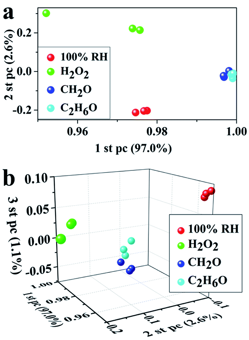 | ||
| Fig. 5 (a) Two-dimensional PCA chart, (b) three-dimensional PCA chart deduced from the average responses of the sensor array containing five sensors based on YFe1−xMnxO3. | ||
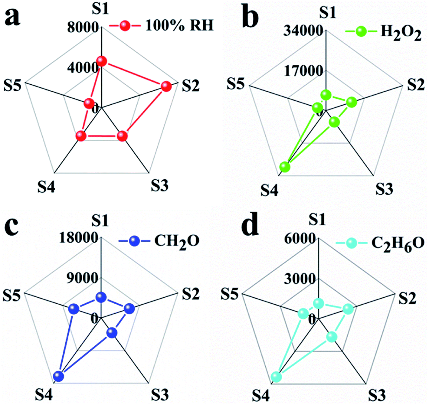
By combining the thermodynamic parameters and dynamic parameters, the digital signals can be transformed into graphic signals, and the visual detection of analytes can be realized by combining the image recognition technology. The response and response time are corresponding to the thermodynamic and kinetic parameters respectively. Therefore, five sensors have five response values and five response times for each analyte. For each analyte, the ratio of five responses to the corresponding five response times leads to five new parameters with thermodynamic and kinetic parameters. These five new parameters are used to build a visual pentagon and shown in Fig. 6. It can be seen from the Fig. 6 that because the S3 has the highest sensitivity, the pentagon looks like a triangle, which reduces the identification of the analyte. Therefore, we reduce the response of S3 to one tenth of the original response under the condition that other parameters remain unchanged, and build a visual pentagon again (Fig. 7). As a result, the visual recognition of four analytes is improved. Thus it can be seen if one wants to build a sensor array with high recognition ability, one need to select and optimize the sensors in the array.
 | ||
| Fig. 6 Characteristic fingerprints deduced by combining kinetic and thermodynamic parameters from sensing data of (a) 100% RH, (b) saturated vapors of H2O2 at room temperature, (c) CH2O, (d) C2H6O. | ||
 | ||
| Fig. 7 Characteristic fingerprints deduced by combining kinetic and thermodynamic parameters from sensing data of (a) 100% RH, (b) saturated vapors of H2O2 at room temperature, (c) CH2O, (d) C2H6O. | ||
Detection limit is an important parameter for estimating gas sensors. The relation between responses and vapour concentrations at RT were shown in Fig. 8. For H2O2 and CH2O vapors, a nearly linear dependency between the response and the concentration in the low concentration range was observed (Fig. 8b and d). At higher concentrations, the response increases more slowly as the concentration increases, which shows that the adsorption of target molecules on the surface of sensing materials gradually reaches saturation. The linear relationship shows that the adsorption of H2O2 and CH2O vapors on YFe0.95Mn0.05O3 has not yet reached saturation in the low concentration range. According to the fitting results in Fig. 8b and d, the estimated LOD (defined as LOD = 3SD/m, where m is the slope of the linear part of the calibration curve and SD is the standard deviation of noise in the response curve) for H2O2 and CH2O is determined to be 1.75 and 2.55 ppb, respectively. These results show the high sensitivity of the YFe0.95Mn0.05O3 to H2O2 and CH2O vapors. This shows that perovskite YFe1−xMnxO3 can be used to measure both high and low concentration atmospheres and it is a very promising gas sensing materials.
 | ||
| Fig. 8 Relation between responses of S3 and vapor concentrations at RT of (a) H2O2, (c) CH2O; the fitting plots of response vs. concentration of (b) H2O2, (d) CH2O. | ||
According to the results of XPS analysis, with the increase of doping amount of Mn ions in YFe1−xMnxO3, the proportion of Mn3+ ion increases and the proportion of Mn2+ decreases. It can be seen that the increase of Mn ions in YFe1−xMnxO3 is significantly faster than the decrease of Mn2+ ion (Table 1). This means that although the proportion of Mn2+ ions decreases gradually, the net Mn2+ concentration increases with the increase of total doping amount of Mn ions. Electronegativity is a relative scale of the ability of atoms or ions to attract electrons. The Mn2+ ions have lower electronegativity than the Mn3+ ions. It means that Mn2+ ions are beneficial to the adsorption of oxygen ions on the surface of YFe1−xMnxO3, while Mn3+ ions are not conducive to the adsorption of oxygen ions. Thus, the competition between Mn2+ ions and Mn3+ ions may lead to an increase and then a decrease in the adsorbed oxygen on the surface of YFe1−xMnxO3 (Fig. 9a).
 | ||
| Fig. 9 (a) The variation of net Mn2+ and Mn3+ concentrations with the increase of Mn doping, and the influence on oxygen adsorption capacity and the charge depletion layer, (b) structural and band models showing the role of Mn doping of the charge depletion layer of YFe1−xMnxO3. | ||
It is known that the depth of charge depletion layer (w) decide the sensing properties of chemiresistive sensors. The classical expressions for the w formed in the semiconductor upon gas adsorption:45,46
| w = LD(2βVS)1/2 | (6) |
 | (7) |
4. Conclusion
Perovskite YFe1−xMnxO3 with hierarchical structure was prepared by simple hydrothermal method and used as gas sensing materials. The gas sensing test showed that YFe1−xMnxO3 with different Mn doping amount displayed fast response and recovery characteristics to multiple target analytes as well as the good stability and recoverability. With the increase of Mn doping concentration, the response of YFe1−xMnxO3 to four kinds of target atmospheres first increases, then decreases. The gas sensing performance of YFe1−xMnxO3 is the best when x = 0.05. Compared with the S1, the response of the S3 to 1000 ppm of CH2O, C2H6O, H2O2 and 100% RH is increased by 835%, 1462%, 812% and 801%, respectively. According to the PCA and radar chart analysis, the sensor array based on YFe1−xMnxO3 can basically identify four kinds of target analytes, and shows higher recognition ability after further data processing. It is feasible to realize the visual and discriminative detection of the target analyte by constructing sensor array through radar chart analysis and database construction.Conflicts of interest
The authors declare no conflict of interest.Acknowledgements
The authors thank the financial support from Natural Science Foundation of Xinjiang Uygur Autonomous Region (2019D01C019), China Postdoctoral Science Foundation (2017M613255) and National Natural Science Foundation of China (21964016, 51602273, 61864011, 11664038).References
- L. Malavasi, C. Tealdi, G. Flor, G. Chiodelli, V. Cervetto, A. Montenero and M. Borella, Sens. Actuators, B, 2005, 105, 407–411 CrossRef CAS.
- Y. Yin, N. Zhang, J. Han, C. Liu, S. Adimi, S. Wen, X. Li and S. Ruan, Sens. Actuators, B, 2019, 297, 126738 CrossRef CAS.
- V. Chumakova, A. V. Marikutsa, M. N. Rumyantseva, D. Fasquelle and A. M. Gaskov, Sens. Actuators, B, 2019, 296, 126661 CrossRef CAS.
- J. W. Fergus, Sens. Actuators, B, 2007, 123, 1169–1179 CrossRef CAS.
- H. Saoudi, A. Benali, M. Bejar, E. Dhahri, T. Fiorido, K. Aguir and R. Hayn, J. Alloys Compd., 2018, 731, 655–661 CrossRef CAS.
- S. Smiy, H. Saoudi, A. Benali, M. Bejar, E. Dhahri, T. Fiorido and K. Aguir, Chem. Phys. Lett., 2019, 735, 136765 CrossRef CAS.
- J. Cerdà, J. Arbiol, G. Dezanneau, R. Díaz and J. R. Morante, Sens. Actuators, B, 2002, 84, 21–25 CrossRef.
- G. Martinelli, M. C. Carotta, M. Ferroni, Y. Sadaoka and E. Traversa, Sens. Actuators, B, 1999, 55, 99–110 CrossRef CAS.
- Y. Hu, O. K. Tan, J. S. Pan, H. Huang and W. Cao, Sens. Actuators, B, 2005, 108, 244–249 CrossRef CAS.
- H. Ying, T. Ooi Kiang, C. Wenqing and Z. Weiguang, IEEE Sens. J., 2005, 5, 825–832 Search PubMed.
- G. G. Mandayo, F. González, I. Rivas, I. Ayerdi and J. Herrán, Sens. Actuators, B, 2006, 118, 305–310 CrossRef CAS.
- Z. Wu, C. Zhou, B. Zu, Y. Li and X. Dou, Adv. Funct. Mater., 2016, 26, 4578–4586 CrossRef CAS.
- L. Shao, Z. Wu, H. Duan and T. Shaymurat, Sens. Actuators, B, 2018, 258, 937–946 CrossRef CAS.
- A. Rothschild, S. J. Litzelman, H. L. Tuller, W. Menesklou, T. Schneider and E. Ivers-Tiffée, Sens. Actuators, B, 2005, 108, 223–230 CrossRef CAS.
- V. I. Popkov, O. V. Almjasheva, A. S. Semenova, D. G. Kellerman, V. N. Nevedomskiy and V. V. Gusarov, J. Mater. Sci.: Mater. Electron., 2017, 28, 7163–7170 CrossRef CAS.
- A. V. Racu, D. Ursu, O. V. Kuliukova, C. Logofatu, A. Leca and M. Miclau, Mater. Lett., 2015, 140, 107–110 CrossRef CAS.
- Z. Lazarevic, C. Jovalekic, M. Gilic, V. N. Ivanovski, A. Umicevic, D. L. Sekulic and Z. N. Romcevic, Sci. Sintering, 2017, 49, 277–284 CrossRef.
- S. Jabbarzare, M. Abdellahi, H. Ghayour, A. Chami and S. Hejazian, J. Alloys Compd., 2016, 688, 1125–1130 CrossRef CAS.
- M. P. F. Graca, L. C. Costa, F. Amaral, M. A. Valente, W. M. Barcellos, F. N. A. Freire, K. D. A. Saboia and A. S. B. Sombra, Spectrosc. Lett., 2017, 50, 206–213 CrossRef CAS.
- P. Mandal, C. Serrao, E. Suard, V. Caignaert, B. Raveau, A. Sundaresan and C. N. R. Rao, J. Solid State Chem., 2013, 197, 408–413 CrossRef CAS.
- C. Zhang, H. Yan, X. Wang, Z. Wang, H. Li and L. Li, Ceram. Int., 2017, 43, 17216–17219 CrossRef CAS.
- S. C. Haw, C. Y. Kuo, Z. Hu, J. W. Lin, J. M. Lee, K. Lu, C. Lee, H. J. Lin, J. F. Lee and C. W. Pao, J. Alloys Compd., 2019, 780, 79–84 CrossRef CAS.
- Z. Yang, Y. Huang, G. Chen, Z. Guo, S. Cheng and S. Huang, Sens. Actuators, B, 2009, 140, 549–556 CrossRef CAS.
- D. Zhang, C. Jiang and J. Wu, Sens. Actuators, B, 2018, 273, 176–184 CrossRef CAS.
- Q. Sun, Z. Wu, H. Duan and D. Jia, Sensors, 2019, 19, 1281 CrossRef CAS PubMed.
- D. J. Norris, A. L. Efros and S. C. Erwin, Science, 2008, 319, 1776 CrossRef CAS PubMed.
- G. Korotcenkov, Sens. Actuators, B, 2005, 107, 209–232 CrossRef CAS.
- B. Deka, S. Ravi, A. Perumal and D. Pamu, Ceram. Int., 2017, 43, 1323–1334 CrossRef CAS.
- A. T. Nguyen, V. N. T. Pham, T. T. L. Nguyen, V. O. Mittova, Q. M. Vo, M. V. Berezhnaya, I. Y. Mittova, T. H. Do and H. D. Chau, Solid State Sci., 2019, 96, 105922 CrossRef CAS.
- Z. Yang and X. Dou, Adv. Funct. Mater., 2016, 26, 2406–2425 CrossRef CAS.
- T. Shaymurat, Q. Tang, Y. Tong, L. Dong and Y. Liu, Adv. Mater., 2013, 25, 2269–2273 CrossRef CAS PubMed.
- Z. M. Xiao, L. B. Kong, S. Ruan, X. Li, S. Yu, X. Li, Y. Jiang, Z. Yao, S. Ye and C. Wang, Sens. Actuators, B, 2018, 274, 235–267 CrossRef CAS.
- M. Shang, C. Zhang, T. Zhang, L. Yuan, L. Ge, H. Yuan and S. Feng, Appl. Phys. Lett., 2013, 102, 062903 CrossRef.
- O. Rosalesgonzalez, F. S. Jesus, C. A. Cortesescobedo and A. M. Bolarinmiro, Ceram. Int., 2018, 44, 15298–15303 CrossRef CAS.
- N. Zhang, S. Liu, X. Fu and Y. Xu, J. Phys. Chem. C, 2011, 115, 9136–9145 CrossRef CAS.
- Y. Tang, L. Liu, H. Zhao, Y. Zhang, L. B. Kong, S. Gao, X. Li, L. Wang and D. Jia, ACS Appl. Mater. Interfaces, 2018, 10, 20225–20230 CrossRef CAS PubMed.
- Z. Zeng, H. Zhou, X. Long, E. Guo and X. Wang, J. Alloys Compd., 2015, 632, 376–385 CrossRef CAS.
- M. Dai, L. Zhao, H. Gao, P. Sun, F. Liu, S. Zhang, K. Shimanoe, N. Yamazoe and G. Lu, ACS Appl. Mater. Interfaces, 2017, 9, 8919–8928 CrossRef CAS PubMed.
- S. YıLmaz, S. Garry, E. McGlynn and E. Bacaksiz, Ceram. Int., 2014, 40, 7753–7759 CrossRef.
- N. Näther, H. Henkel, A. Schneider and M. J. Schöning, Phys. Status Solidi A, 2009, 206, 449–454 CrossRef.
- E. Capua, R. Cao, C. N. Sukenik and R. Naaman, Sens. Actuators, B, 2009, 140, 122–127 CrossRef CAS.
- A. Lichtenstein, E. Havivi, R. Shacham, E. Hahamy, R. Leibovich, A. Pevzner, V. Krivitsky, G. Davivi, I. Presman and R. Elnathan, Nat. Commun., 2014, 5, 4195 CrossRef CAS PubMed.
- Q. Sun, Z. Wu, Y. Cao, J. Guo, M. Long, H. Duan and D. Jia, Sens. Actuators, B, 2019, 297, 126689 CrossRef CAS.
- Z. Chen, Y. Yang, Y. Xie, B. Guo and Z. Hu, Sens. Actuators, A, 2013, 201, 66–72 CrossRef CAS.
- N. Yamazoe and K. Shimanoe, Sens. Actuators, B, 2008, 128, 566–573 CrossRef CAS.
- M. Epifani, J. D. Prades, E. Comini, E. Pellicer, M. Avella, P. Siciliano, G. Faglia, A. Cirera, R. Scotti and F. Morazzoni, J. Phys. Chem. C, 2008, 112, 19540–19546 CrossRef CAS.
- G. Zhang and M. Liu, Sens. Actuators, B, 2000, 69, 144–152 CrossRef CAS.
Footnote |
| † Electronic supplementary information (ESI) available. See DOI: 10.1039/d0ra01375g |
| This journal is © The Royal Society of Chemistry 2020 |