
 Open Access Article
 This Open Access Article is licensed under a Creative Commons Attribution-Non Commercial 3.0 Unported Licence
Functionalizing triptycene to create 3D high-performance non-fullerene acceptors†
Yezi Yanga,
Chuang Yao *a,
Lei Lia,
Maolin Boa,
Jianfeng Zhang*b,
Cheng Penga and
Jinshan Wang*c
*a,
Lei Lia,
Maolin Boa,
Jianfeng Zhang*b,
Cheng Penga and
Jinshan Wang*c
aKey Laboratory of Extraordinary Bond Engineering and Advance Materials Technology (EBEAM) of Chongqing, School of Materials Science and Engineering, Yangtze Normal University, Chongqing 408100, P. R. China. E-mail: yaochuang@yznu.cn
bCollege of Physics and Optoelectronic Engineering, Shenzhen University, Shenzhen 518060, P. R. China. E-mail: wangjinshan@ycit.cn
cSchool of Materials Science and Engineering, Yancheng Institute of Technology, Yancheng 224051, P. R. China. E-mail: zjfgood@live.com
First published on 24th March 2020
Abstract
Non-fullerene acceptors have been widely investigated for organic solar cells (OSCs). In particular, fused-ring electron acceptors (FREAs), composed of two strongly electron-withdrawing end groups connected by a planar fused-ring core, have been successfully applied to develop high-performance OSCs (>16%). In this work, we proposed two novel 3D FREAs named BFT-3D and BFTT-3D, which can reduce the formation of crystalline domains and increase the interface with donors to promote exciton separation. These 3D FREAs consist of three strongly electron-withdrawing end groups linked by a central triptycene hub to form a three-bladed propeller nanostructure. In comparison with high-performance FREA (ITOIC-2F), these FREAs have stronger absorption intensity and smaller exciton binding energy. These findings demonstrated that these three-bladed propeller-shaped FREAs can absorb abundant energy from sunlight to generate excitons, easily separate excitons to free electrons and holes, and reduce the recombination of excitons. In addition, the electron mobility of BFT-3D (8.4 × 10⁻⁴ cm2 V−1 s−1) is higher than that of BFTT-3D (1.0 × 10⁻⁴ cm2 V−1 s−1), which indicated that the appropriate 3D core structure was conducive to the electron mobility of the three-bladed propeller-shaped FREAs. It can effectively improve the current density to enhance the performance of OSCs. These findings will provide new perspectives for experimental scientists to synthesize high-performance FREAs.
Introduction
Organic solar cells (OSCs) have attracted considerable attention because of their promising performance in the low-cost conversion of solar energy. OSCs are also lightweight, flexible, and semi-transparent devices that can be used for large-area devices.1–4 The most common OSCs typically consist of an electron donor and an electron acceptor to form a bulk heterojunction (BHJ), which can effectively increase the exciton separate interface to promote the generation of free holes and electrons. Therefore, the optoelectronic properties of donors and acceptors play a key role in the efficiency of OSCs. Non-fullerene acceptors (NFAs) have gained considerable attention because of their easy and flexible synthesis, variable energy levels and electron affinities, and increased visible and near-infrared absorptivity.5–10 The power conversion efficiencies (PCE) of OSCs based on NFAs have already exceeded 15%.11,12NFAs have been used for a long history, and in fact that the first reported bilayer OSCs were based on perylene NFAs.13 However, in recent decades, fullerene and its derivatives, benefitting from their strong electron affinity and high electron mobility, are the most widely used acceptors.14–16 Until recently, NFAs have been widely explored because of the bottlenecks in developing fullerene-based OSCs. This drawback is due to the narrow and weak absorption of sunlight and the poor adjustability of the energy levels17,18 of fullerene and its derivatives, resulting in their limited PCE of 12%.19–23 Thus far, two classes of NFAs have been developed: rylene diimides24–26 and fused-ring electron acceptors (FREAs).27–31 Many rylene diimides form 1D stacks in the BHJ, thereby limiting the percolation pathways for charges and leading to a lack of electron-transport pathways from active layer to electrodes, resulting in a limitation in the PCE of OSCs.32 Recently, FREAs, composed of two strongly electron-withdrawing end groups connected by a planar fused-ring core, have been investigated by considerable efforts. The frontier molecular orbital energy levels, ionization energy and electron affinity, absorption wavelength, and solubility can be tuned by varying the fused-ring cores,33,34 electron-withdrawing groups,35,36 and side chains.29,37
Typical FREAs, such as ITIC38 and IT-4F,39 feature an acceptor–donor–acceptor (A–D–A) planar architecture, which can facilitate local π–π stacking between intermolecular terminal moieties to provide the main charge transfer channels.40 Therefore, end groups play a critical role in the performance of FREAs. The most common end groups are 1,1-dicyanomethylene-3-indanone and its derivatives (methylation or fluorination).29,41 Fluorination can lead to red-shifted absorptions, increased electron affinity,42 and production of intermolecular F–π interactions, thereby increasing electron mobilities.43 For example, ITOIC-2F utilizing di-fluorinated 1,1-dicyanomethylene-3-indanone as end groups exhibit a high PCE of 12.17% combined with a polymer donor PBDB-T.41 All these benefits result in PCE of 15%12 and 16%11 of currently reported OSCs.
Furthermore, fused-ring cores also significantly affect the performance of FREAs. Dialkylcyclopentadiene and diarylcyclopentadiene rings are typically fused with thiophene, selenophene, and benzene as fused-ring cores.27,28,38,44 These fused-ring cores are usually combined with end groups to form linear FREAs, such as ITIC,38 IT-4F,39 and ITOIC-2F.41 Recently, benzotri(cyclopentadithiophene) is used as an electron-rich core for star-shaped FREAs, and a high PCE yield of 8.11% is achieved.45 In our previous work, we proposed a novel 2D fused-ring core to design quad-rotor-shaped FREAs.10 In comparison with widely used non-fullerene acceptor ITICs, these FREAs have lower frontier molecular orbital energy levels, greater electron affinity, stronger absorption coefficients, smaller exciton binding energy, and higher electron mobility. For these reasons, FREAs have been actively explored as potential alternatives to fullerenes in OSCs.
On the downside, linear-shaped, star-shaped, or 2D FREAs show planar structures, which are much more challenging to achieve both small domain sizes and sufficient electron mobilities. The problem is that large planar structures tend to form excessively large crystalline domains,46 which can improve electron transport but reduce the donor and acceptor interfaces and impair the exciton separation. Furthermore, most FREAs cannot form a 3D charge-transporting network as readily as fullerenes do. Therefore, breaking the inherent planar structural characteristics of existing FREAs and designing FREAs with new structural features have important research significance.
In this work, we proposed two novel 3D FREAs named BFT-3D and BFTT-3D. These 3D FREAs consist of three di-fluorinated 1,1-dicyanomethylene-3-indanone electron-withdrawing end groups linked by a central triptycene hub to form a three-bladed propeller nanostructure. ITOIC-2F, which has the same end groups with these 3D FREAs, is used as a reference in this work. In comparing with ITOIC-2F, BFT-3D and BFTT-3D shown stronger absorption intensity and smaller exciton binding energy, which suggested that these three-bladed propeller-shaped FREAs can absorb abundant energy from sunlight and generate numerous excitons. The excitons can separate to free electrons and holes easily and the recombination of excitons can be reduced. In addition, the electron mobilities of BFT-3D and BFTT-3D are on the same order of magnitude as the electron mobility of ITOIC-2F. These results implied that three-bladed propeller-shaped FREAs are potentially important candidates for next-generation FREAs for high-performance OSCs, thereby providing new ideas for experimental scientists to synthesize high-performance FREAs.
Computational method
Quantum chemical calculations
The ground state geometry optimization and vibration frequency of ITOIC-2F, BFT-3D and BFTT-3D were calculated at the BLYP/def2-SVP level with the geometrical counterpoise correction to remove artificial overbinding effects from the basis set superposition error.47 No imaginary frequency was detected on the same calculation, indicating that the minimum energy states were found. The highest occupied molecular orbital (HOMO) and LUMO energy levels, vertical electron affinities, electron reorganization energies (λ−), spatial distribution of the frontier molecular orbitals are calculated at B3LYP/def2-TZVP level. The PBE0 hybrid functional can estimate a reasonable colour for most organic materials by time-dependent density functional theory.48 Therefore, PBE0/def2-SVPD is used to investigate the absorption spectra of these materials in chloroform, in which the atom-pairwise dispersion correction (D3ZERO) is used to account for the major parts of dispersion forces contribution to the energy.49 The excited states analysis and natural transition orbitals analysis are obtained using the Multiwfn 3.6 package.50 All quantum chemical calculations are carried out based on ORCA Revision 4.1.0 program.51Multiscale simulations
The electron mobilities of ITOIC-2F, BFT-3D, and BFTT-3D amorphous thin films were evaluated by a multiscale simulation based on quantum chemical calculations, molecular dynamics (MD) simulations, and Monte Carlo (MC) calculations, as detailed simulation processes were described in our previous works.43,52,53The geometry of ITOIC-2F, BFT-3D, and BFTT-3D are optimized using the quantum chemical calculations as mentioned above. Gromacs 5.1.4 molecular dynamic (MD) simulation package54 is used to accomplish the MD simulations for all systems. Universal Force Field55 model is used as the atomistic force field for all simulated systems. The amorphous systems for ITOIC-2F, BFT-3D, and BFTT-3D are constructed and imitated using the same procedure as described in our early work.53 First, 200 molecules were randomly added in a large box (10 × 10 × 10 nm3) to generate the initial amorphous system. Second, 50![[thin space (1/6-em)]](https://www.rsc.org/images/entities/char_2009.gif) 000 steps of the steepest descent were carried out on the systems to remove the undesired forces and structure distortion. Third, 5 ns simulation at 600 K and 100 bar were used to quickly make the molecules close enough. Fourth, the systems were annealed between 300 and 420 K for six times in 10 ns. Finally, the systems were maintained at 300 K for 20 ns to achieve completely converged systems, which were used as the model of amorphous films to evaluate the electron mobilities.
000 steps of the steepest descent were carried out on the systems to remove the undesired forces and structure distortion. Third, 5 ns simulation at 600 K and 100 bar were used to quickly make the molecules close enough. Fourth, the systems were annealed between 300 and 420 K for six times in 10 ns. Finally, the systems were maintained at 300 K for 20 ns to achieve completely converged systems, which were used as the model of amorphous films to evaluate the electron mobilities.
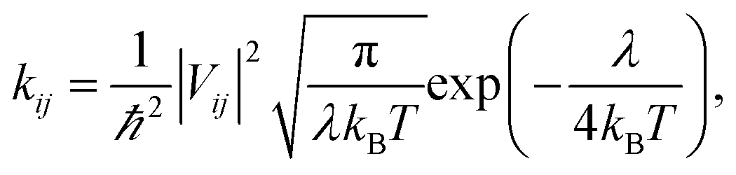
Hopping model were used to calculate the electron mobilities of the amorphous films of ITOIC-2F, BFT-3D, and BFTT-3D. The hopping rate from one molecule to the adjacent molecules can be described by the Marcus formula,56 as follows:
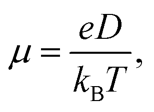
In hopping model, the charge-transport can be described as a diffusion process. In the low-field limit, the carrier mobility can be well-described by the Einstein formula
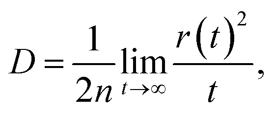
where r(t)2 is the square displacement. Therefore, the key point to calculate the electron mobility is simulating the charge-diffusion coefficient, which is proportional to the slope of r(t)2 and t. To estimate the charge-diffusion coefficient, we used a Monte Carlo calculation to simulate the diffusion process,53 wherein the charge-carrier hops between adjacent molecules according to the hopping rate (kij).
We constructed the adjacent molecular pairs (the shortest interatomic distance is less than 0.5 nm) for each molecule under periodic conditions based on the model of amorphous films obtained from the MD simulations. The center-of-mass (COM) of each molecular were utilized as the hopping point in the MC simulations. During the hopping process, we first randomly selected one molecule (i) as the initial charge center. Then, the charge hops between the center molecule (i) and its adjacent molecule (j) with a probability of Pij = kij/∑kij. The hopping time was defined as 1/kij, and the hopping distance was taken to be the molecular COM(i)–COM(j) distance. Finally, we used the hopping coordinate and time to build the relationship between square displacement and the diffusion time to estimate the diffusion coefficient.
Results and discussion
Molecular design and geometry
In our previous work, we demonstrated that fluorination can effectively inverse the electrostatic potential and produce intermolecular F–π interactions to improve electron mobilities in the ITOIC-2F amorphous film.43 Therefore, we utilized di-fluorinated 1,1-dicyanomethylene-3-indanone as the electron-withdrawing end groups to construct new FREAs. To break the inherent planar structural characteristics of most existing FREAs, which may reduce the degree of phase separation, we used a central triptycene hub as a core structure to design three-bladed propeller-shaped FREAs. The chemical structure of ITOIC-2F, BFT-3D, and BFTT-3D and their optimized spatial structure at the top and side views are shown in Fig. 1. ITOIC-2F was used as a reference in this work because it has the same end groups. In comparing with ITOIC-2F, BFT-3D and BFTT-3D exhibit a 3D structure similar to that of three-bladed propeller. Each blade consists of a di-fluorinated 1,1-dicyanomethylene-3-indanone end group, and the blades form an angle of 120° with each other. This 3D structure can reduce the requirement for its orientation with respect to the donor, in principle which can affect the energetics and dynamics of charge separation.58 Therefore, this distinct structure may impart different optoelectronic properties to BFT-3D and BFTT-3D.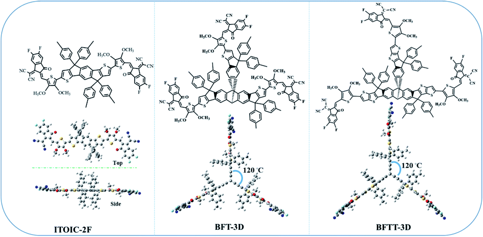 | ||
| Fig. 1 Chemical structure of ITOIC-2F, BFT-3D, and BFTT-3D and the optimized spatial structure in top and side view. | ||
Electronic properties
The energy levels of frontier molecular orbitals, such as HOMO and LUMO, can affect exciton separation, charge transportation, and open-circuit voltage in OSCs.58 Thus, the HOMO and LUMO energy levels of BFT-3D and BFTT-3D compared with the reference ITOIC-2F are shown in Fig. 2.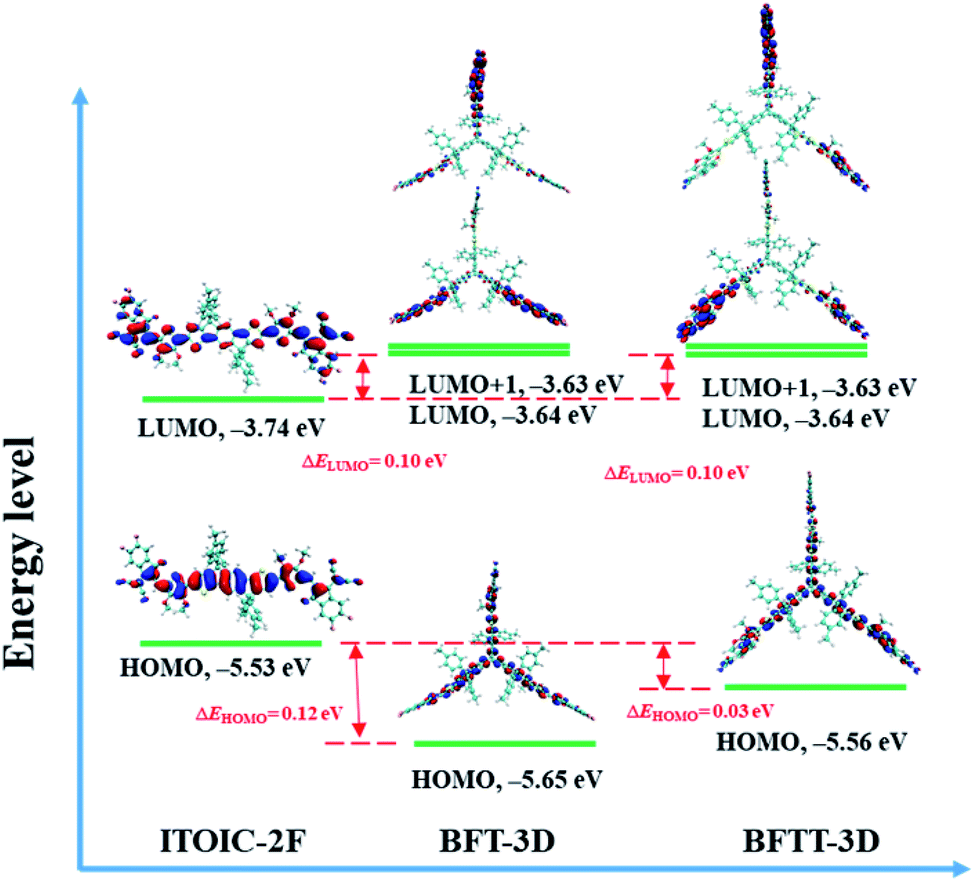 | ||
| Fig. 2 Energy levels and the spatial distributions of the frontier molecular orbitals of ITOIC-2F, BFT-3D and BFTT-3D. | ||
The HOMO and LUMO energy levels of ITOIC-2F are −5.53 and −3.74 eV, respectively, which are in good agreement with the experimental results (−5.57 and −3.87 eV).41 These results demonstrate the accuracy of the calculation method. Both BFT-3D and BFTT-3D have a LUMO energy level of −3.64 eV, which is slightly higher (0.1 eV) than that of ITOIC-2F. Compared with ITOIC-2F, BFT-3D and BFTT-3D exhibit a similar electron acceptability. The vertical electron affinity of ITOIC-2F, BFT-3D and BFTT-3D are 3.12, 3.10 and 3.12 eV, respectively. The difference between LUMO and LUMO+1 energy level of BFT-3D and BFTT-3D are evidently only 0.01 eV, which implies the degeneracy of LUMO and LUMO+1. The HOMO energy levels of BFT-3D and BFTT-3D are 0.12 and 0.03 eV lower than that of ITOIC-2F. The HOMO energy level difference between the donor and these 3D FREAs can be increased, thereby increasing the rate of exciton separation at donor and 3D FREAs interfaces.
The distribution of LUMO significantly affects electronic transportation.52 Therefore, the spatial distribution of the frontier molecular orbitals of ITOIC-2F, BFT-3D, and BFTT-3D are inserted in Fig. 2. The LUMO of ITOIC-2F is delocalized from the fused-ring core to the end groups to form a linear distribution indicating that the electron transport within the molecule is in a line and may result in an anisotropic electron transport phenomenon. However, for BFT-3D and BFTT-3D, their degenerated LUMO and LUMO+1 orbitals are distributed on the end groups of the three blades. To further investigate the electron distribution when the acceptor materials accept an electron, we calculated the distribution of the obtained electrons for ITOIC-2F, BFT-3D and BFTT-3D as shown in Fig. 3. The obtained electron is delocalized on the whole backbone of ITOIC-2F, which is in agreement with the LUMO distribution. In the three-bladed propeller-shaped acceptor BFT-3D and BFTT-3D, the obtained electron is mainly localized on the end groups and has a slight distribution on the triptycene hub. Therefore, electrons can be transported in three directions within these molecules, facilitating the non-directional electron transport to reduce its dependence on the crystallographic direction. Thus, electrons can be transported in three directions within molecules and are advantageous for increasing the percolation pathways for electron transport in amorphous films.
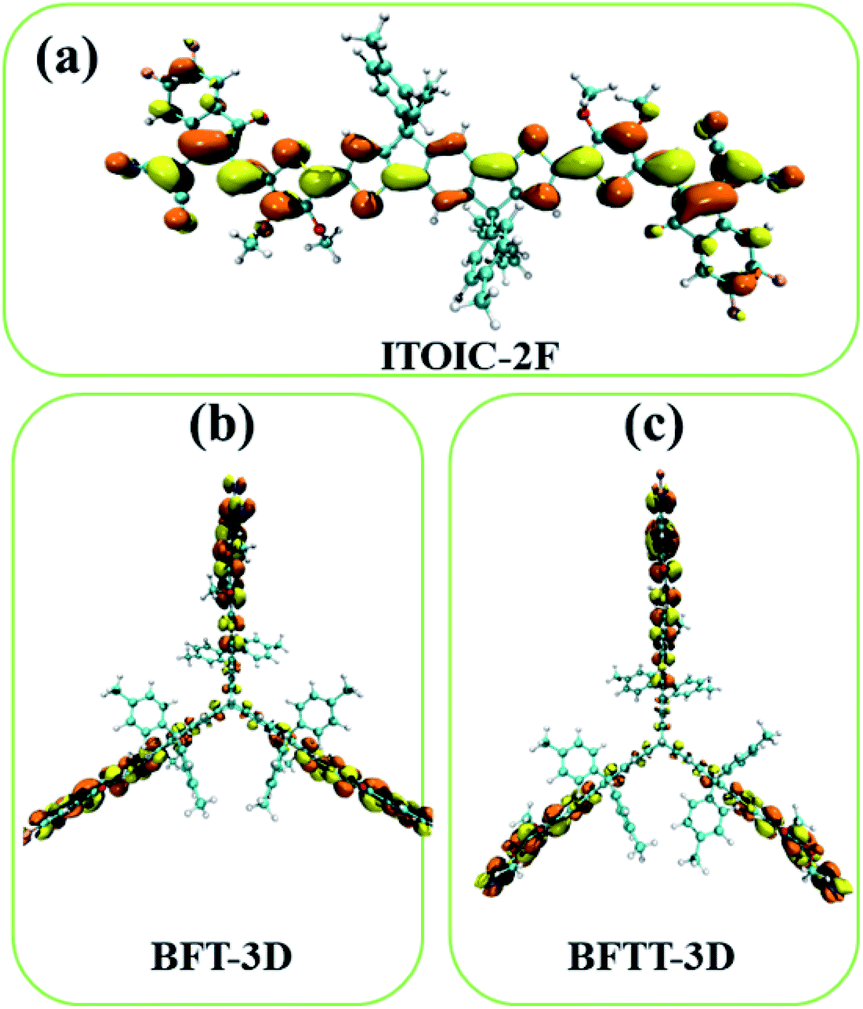 | ||
| Fig. 3 Electron distribution of ITOIC-2F (a), BFT-3D (b) and BFTT-3D (c) when they obtained an electron. Isovalue = 0.015 a.u. | ||
As described by Marcus formula,59 electron reorganization energy (λ−) influences electron transport. λ− of ITOIC-2F, BFT-3D, and BFTT-3D are 0.120, 0.065, and 0.062 eV, respectively. The detailed results are summarized in Table 1. λ− of the three-bladed propeller-shaped acceptors are remarkably lower than that of ITOIC-2F and can facilitate the electron transport in these materials.
| HOMO (eV) | LUMO (eV) | LUMO+1 (eV) | ΔEg | VEA (eV) | λ− (eV) | |
|---|---|---|---|---|---|---|
| ITOIC-2F | −5.53 | −3.74 | −3.51 | 1.79 | 3.12 | 0.120 |
| BFT-3D | −5.65 | −3.64 | −3.63 | 2.01 | 3.10 | 0.065 |
| BFTT-3D | −5.56 | −3.64 | −3.63 | 1.92 | 3.12 | 0.062 |
Absorption spectra
Excellent FREAs should exhibit strong absorption in areas of the solar spectrum with high irradiance to generate more excitons and improve the PCE of OSCs. Therefore, investigating the absorption spectra of these three-bladed propeller-shaped FREAs has important significance. Here, we utilized time-dependent density functional theory to estimate the electronic excitation of ITOIC-2F, BFT-3D, and BFTT-3D in chloroform. The absorption spectra shown in Fig. 4(a) were generated by using Multiwfn 3.6 in combination with Gaussian broadening function and a fixed full width at half maximum (0.2 eV). The absorption peak and absorption coefficient of ITOIC-2F are 763 nm and 4.7 × 10⁵ L mol−1 cm−1, respectively. These values are in agreement with the experimental data of 737 nm and 1.69 × 10⁵ L mol−1 cm−1.41 They also demonstrate the reliability of the calculation method. The calculated absorption spectra of BFT-3D and BFTT-3D show two strong absorption peaks at 592/716 and 647/769 nm, respectively. This phenomenon broadens the absorption spectrum in the visible range, and their FWHM values are 160 and 195 nm, respectively. They are considerably wider than that of ITOIC-2F (94 nm). A good match between FREAs's absorption spectrum with the solar spectrum can increase the absorption of solar energy. The solar spectrum of air mass zero (AM0) in Fig. S1† indicates that the main irradiation region where the irradiance is larger than half of the highest intensity is 383–799 nm. The main absorption region where the absorption coefficient is larger than half of the highest absorption of ITOIC-2F is 719–813 nm, which overlaps with the main irradiation region of solar spectrum by 80 nm. The main absorption regions of BFT-3D and BFTT-3D overlap with the main irradiation region of the solar spectrum by 160 and 173 nm, respectively. The integrated intensity of the absorption spectra was descripted in Fig. 4(b). The integrated intensity of BFT-3D and BFTT-3D were 1.2 and 1.5 times that of ITOIC-2F, respectively. These findings demonstrated that BFT-3D and BFTT-3D can absorb more sunlight to generate additional excitons and improve the performance of corresponding OSCs.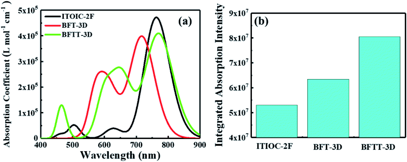 | ||
| Fig. 4 The molar absorption coefficient (a) and integrated absorption intensity (b) of ITOIC-2F, BFT-3D and BFTT-3D in chloroform. | ||
To get deeper inside of the absorption spectra, the contribution of each electron excited states to the absorption spectra of ITOIC-2F, BFT-3D, and BFTT-3D was shown in Fig. 5. The charge density difference for each excited state with oscillator strength larger than 1.00 is inserted in the related location. These results were calculated by Multiwfn 3.6 package.50 The absorption spectrum of ITOIC-2F is mainly dominated by S0 → S1 transition (764 nm) with f of 3.46. The charge density difference of this electron excited state indicated the electron transfer from the center to the end groups, which was mainly dominated by the transition from HOMO to LUMO (96%). The absorption spectra of BFT-3D and BFTT-3D consist of three major transition processes with f larger than 1.00, namely, S0 → S1 (716 nm), S0 → S2 (732 nm), and S0 → S4 (614 nm) for BFT-3D, and S0 → S1 (755 nm), S0 → S2 (781 nm), and S0 → S7 (659 nm) for BFTT-3D. The molecular orbital (MO) contribution to each excited state was summarized in Table 2. The charge density difference of these excited states shows the electron transport from the 3D center to the three end groups during excitation, thereby increasing the interface between end groups and donors and the probability of exciton separation.
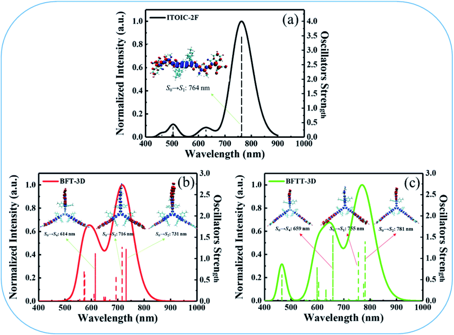 | ||
| Fig. 5 Detailed electron excited states contribute to the absorption spectra of ITOIC-2F (a), BFT-3D (b), and BFTT-3D (c), the charge density difference (blue: positive; red: negative) for each excited state with oscillator strength larger than 1.00 is inserted in the related location. | ||
| Excited states | λ (nm) | f | MOa contribution | Ec (eV) |
|---|---|---|---|---|
| a H = HOMO, H−1 = HOMO−1, H−2 = HOMO−2, L = LUMO, L+1 = LUMO+1, L+2 = LUMO+2. | ||||
| ITOIC-2F | ||||
| S0 → S1 | 764 | 3.46 | H → L (97%) | 1.86 |
|
||||
| BFT-3D | ||||
| S0 → S1 | 716 | 1.29 | H → L (96%) | 1.19 |
| S0 → S2 | 731 | 1.23 | H → L+1 (96%) | 1.14 |
| S0 → S4 | 614 | 1.12 | H−2 → L+2 (79%) | 1.16 |
|
||||
| BFTT-3D | ||||
| S0 → S1 | 755 | 1.19 | H → L (96%) | 1.09 |
| S0 → S2 | 781 | 1.41 | H → L+1 (94%) | 1.05 |
| S0 → S4 | 659 | 1.55 | H−1 → L+1 (52%) | 1.04 |
| H−2 → L (52%) | ||||
When the acceptors absorb solar energy, they generate numerous excited states, which dissociate into separate (non-coulombically bound) holes and electrons to form free charges at the acceptor and donor interface. Therefore, the strength of exciton binding energy (Ec) also affects the efficiency of OSCs. Here, we utilized electron–hole theory by using Multiwfn 3.6 package50 to calculate Ec of each excited state. Ec is defined as the Coulomb attraction between a hole and an electron and produced during electron transition. It is calculated via a simple Coulomb formula:
Amorphous films
As the active layer of OSCs is usually spin-coated by a solution method and thermally annealed for ∼10 min to form an amorphous film. To discuss the aggregation properties, we investigated the center-of-mass radial distribution functions of BFT-3D and BFTT-3D amorphous films on the basis of molecular dynamic simulation systems as shown in Fig. 6(a). No distinct peaks formed in all these materials; the radial distribution function approaches to 1.0 when the center-of-mass distance of the electron-withdrawing end group is larger than 1.5 nm, confirming an amorphous arrangement in these films.60 The first peaks of both BFT-3D and BFTT-3D appear around 0.4 nm, respectively. As such, these novel three-bladed propeller-shaped FREAs can form a close accumulation, which beneficial to the electron transport. These amorphous films were used to construct the molecular dimer for electron transport networks as described in our early studies.43,52,53 To investigate the transfer integral of the whole dimers in these amorphous films, we showed the normalized distribution of the transfer integral (V) of whole system of BFT-3D and BFTT-3D in Fig. 6(b). The V of BFT-3D and BFTT-3D are distributed in 0–0.15 and 0–0.12 eV regions, respectively. Compared with BFTT-3D, BFT-3D exhibited a slight distribution in the region of 0.12–0.15 eV, which plays a major role in the actual electron transport, indicating BFT-3D may exhibit higher electron mobility than that of BFTT-3D.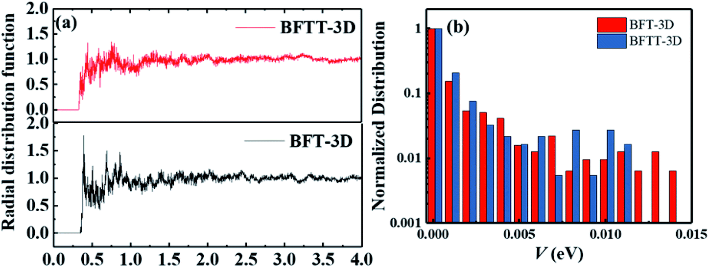 | ||
| Fig. 6 (a) Center-of-mass radial distribution functions of the electron-withdrawing end group of BFT-3D and BFTT-3D. (b) Normalized distribution of the transfer integral of the of BFT-3D and BFTT-3D. | ||
Electron mobilities
In addition to absorbing solar energy and separating excitons, the electron mobility of FREAs plays a decisive role in the performance of OSCs because a high electron mobility can facilitate electron transport and collection. Here, we used a multiscale simulation method as described in our early works43,52,53 to identify the electron mobilities of BFT-3D and BFTT-3D amorphous films.Further, utilizing the results of the Monte Carlo simulations, the squared displacement of five typical simulations and average over 2000 times versus the simulation time for the hole and electron diffusion of BFT-3D and BFTT-3D are shown in Fig. 7. Although the data for each Monte Carlo simulation do not have linear characteristics, the average of over 2000 times exhibits a good linear relationship. The electron diffusion constant can be estimated from the slope of the linear data. To demonstrate the reliability of this calculation method, the electron mobility of ITOIC-2F was estimated to be 4.2 × 10⁻⁴ cm2 V−1 s−1 as shown in Fig. S2,† which is agreement with the experimental result (6.0 × 10⁻⁴ cm2 V−1 s−1)41 and demonstrates the reliability of this simulation method. The electron mobilities are estimated to be 1.0 × 10⁻⁴ and 8.4 × 10⁻⁴ cm2 V−1 s−1 for BFT-3D and BFTT-3D, respectively. These results are on the same order of magnitude as the electron mobility of ITOIC-2F. Thus, although the 3D structure has interrupted the original planar structure of the linear-shaped FREAs, these three-bladed propeller-shaped FREAs can maintain the original electron transport ability. BFT-3D exhibit much higher electron transport properties than that of BFTT-3D, which is in good agreement with the results of the distribution of V discussed above. Thus, the increase in the size of the 3D core structure was not conducive to the electronic transportation of three-bladed propeller-shaped FREAs while maintaining the electron-withdrawing end group unchanged. This finding will provide a new perspective for experimental scientists to synthesize 3D FREAs with high electron mobility.
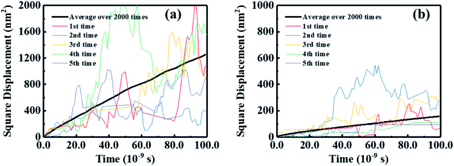 | ||
| Fig. 7 Squared displacement of five typical simulations and average over 2000 times versus the simulation time for electron diffusion of BFT-3D (a), and BFTT-3D (b). | ||
Conclusions
In summary, we proposed two novel 3D FREAs, namely, BFT-3D and BFTT-3D. These 3D FREAs consist of three di-fluorinated 1,1-dicyanomethylene-3-indanone electron-withdrawing end groups linked by a central triptycene hub to form a three-bladed propeller nanostructure. BFT-3D and BFTT-3D exhibit two strong absorption peaks at 592/716 and 647/769 nm, respectively. This phenomenon broadens the absorption spectrum in the visible range, and their FWHM values are 160 and 195 nm. The absorption integrated intensity of BFT-3D and BFTT-3D were 1.2 and 1.5 times that of ITOIC-2F. These results demonstrated that three-bladed propeller-shaped FREAs can absorb more energy from sunlight and generate more excitons. In addition, the exciton binding energies for each excitation state (with oscillator strength > 1.0) of BFT-3D (S0–S1: 1.19 eV; S0–S2: 1.14 eV; S0–S4: 1.16 eV) and BFTT-3D (S0–S1: 1.09 eV; S0–S2: 1.05 eV; S0–S8: 1.04 eV) are smaller than that of ITOIC-2F (S0–S1: 1.86 eV). These findings suggested that they can easily separate excitons to free electrons and holes, and reduce the recombination of excitons. Furthermore, the electron mobility of BFT-3D is 8.4 × 10⁻⁴ cm2 V−1 s−1, which is higher than that of BFTT-3D (1.0 × 10⁻⁴ cm2 V−1 s−1) and ITOIC-2F (4.2 × 10⁻⁴ cm2 V−1 s−1). All these properties imply that three-bladed propeller-shaped FREAs with a proper 3D core structure are efficient acceptors for high-performance OSCs. These findings will provide new perspectives for experimental scientists to synthesize high-performance FREAs.Conflicts of interest
There are no conflicts to declare.Acknowledgements
The authors acknowledge financial support from the National Natural Science Foundation of China (11804033, 11904033), the Advanced Research Projects of Chongqing Municipal Science and Technology Commission (cstc2017jcyjA1630, cstc2019jcyj-msxmX0674), the Science and Technology Research Program of Chongqing Municipal Education Commission (KJ1712297) and the Scientific Research Grants of Yangtze Normal University (2017XJQN04).Notes and references
- F. C. Krebs, N. Espinosa, M. Hösel, R. R. Søndergaard and M. Jørgensen, Adv. Mater., 2014, 26, 29–39 CrossRef CAS PubMed.
- L. Dou, Y. Liu, Z. Hong, G. Li and Y. Yang, Chem. Rev., 2015, 115, 12633–12665 CrossRef CAS PubMed.
- C. B. Nielsen, S. Holliday, H.-Y. Chen, S. J. Cryer and I. McCulloch, Acc. Chem. Res., 2015, 48, 2803–2812 CrossRef CAS.
- Y. Liu, C. Mu, K. Jiang, J. Zhao, Y. Li, L. Zhang, Z. Li, J. Y. L. Lai, H. Hu, T. Ma, R. Hu, D. Yu, X. Huang, B. Z. Tang and H. Yan, Adv. Mater., 2015, 27, 1015–1020 CrossRef CAS.
- N. Schmid, A. P. Eichenberger, A. Choutko, S. Riniker, M. Winger, A. E. Mark and W. F. van Gunsteren, Eur. Biophys. J., 2011, 40, 843 CrossRef CAS PubMed.
- Z. Zhang, M. Li, Y. Liu, J. Zhang, S. Feng, X. Xu, J. Song and Z. Bo, J. Mater. Chem. A, 2017, 5, 7776–7783 RSC.
- P. Cheng, G. Li, X. Zhan and Y. Yang, Nat. Photonics, 2018, 12, 131–142 CrossRef CAS.
- G. Han, Y. Guo, L. Ning and Y. Yi, Sol. RRL, 2018, 0, 1800251 Search PubMed.
- J. Hou, O. Inganäs, R. H. Friend and F. Gao, Nat. Mater., 2018, 17, 119 CrossRef CAS.
- C. Yao, Y. Yang, L. Li, M. Bo, C. Peng and J. Wang, J. Mater. Chem. A, 2019, 7, 18150–18157 RSC.
- B. Fan, D. Zhang, M. Li, W. Zhong, Z. Zeng, L. Ying, F. Huang and Y. Cao, Sci. China: Chem., 2019, 62, 746–752 CrossRef CAS.
- J. Yuan, Y. Zhang, L. Zhou, G. Zhang, H.-L. Yip, T.-K. Lau, X. Lu, C. Zhu, H. Peng, P. A. Johnson, M. Leclerc, Y. Cao, J. Ulanski, Y. Li and Y. Zou, Joule, 2019, 3, 1140–1151 CrossRef CAS.
- C. W. Tang, Appl. Phys. Lett., 1986, 48, 183–185 CrossRef CAS.
- C. Yao, X. Xu, J. Wang, L. Shi and L. Li, ACS Appl. Mater. Interfaces, 2013, 5, 1100–1107 CrossRef CAS PubMed.
- Q. Wan, X. Guo, Z. Wang, W. Li, B. Guo, W. Ma, M. Zhang and Y. Li, Adv. Funct. Mater., 2016, 26, 6635–6640 CrossRef CAS.
- J. Fang, D. Deng, J. Zhang, Y. Zhang, K. Lu and Z. Wei, Mater. Chem. Front., 2017, 1, 1223–1228 RSC.
- Y. He and Y. Li, Phys. Chem. Chem. Phys., 2011, 13, 1970–1983 RSC.
- L. J. A. Koster, V. D. Mihailetchi and P. W. M. Blom, Appl. Phys. Lett., 2006, 88, 093511 CrossRef.
- J.-D. Chen, C. Cui, Y.-Q. Li, L. Zhou, Q.-D. Ou, C. Li, Y. Li and J.-X. Tang, Adv. Mater., 2015, 27, 1035–1041 CrossRef CAS PubMed.
- Y. Jin, Z. Chen, S. Dong, N. Zheng, L. Ying, X.-F. Jiang, F. Liu, F. Huang and Y. Cao, Adv. Mater., 2016, 28, 9811–9818 CrossRef CAS PubMed.
- T. Liu, X. Pan, X. Meng, Y. Liu, D. Wei, W. Ma, L. Huo, X. Sun, T. H. Lee, M. Huang, H. Choi, J. Y. Kim, W. C. H. Choy and Y. Sun, Adv. Mater., 2017, 29, 1604251 CrossRef PubMed.
- G. Long, R. Shi, Y. Zhou, A. Li, B. Kan, W.-R. Wu, U. S. Jeng, T. Xu, T. Yan, M. Zhang, X. Yang, X. Ke, L. Sun, A. Gray-Weale, X. Wan, H. Zhang, C. Li, Y. Wang and Y. Chen, J. Phys. Chem. C, 2017, 121, 5864–5870 CrossRef CAS.
- G. Long, A. Li, R. Shi, Y.-C. Zhou, X. Yang, Y. Zuo, W.-R. Wu, U. S. Jeng, Y. Wang, X. Wan, P. Shen, H.-L. Zhang, T. Yan and Y. Chen, Adv. Electron. Mater., 2015, 1, 1500217 CrossRef.
- P. E. Hartnett, A. Timalsina, H. S. S. R. Matte, N. Zhou, X. Guo, W. Zhao, A. Facchetti, R. P. H. Chang, M. C. Hersam, M. R. Wasielewski and T. J. Marks, J. Am. Chem. Soc., 2014, 136, 16345–16356 CrossRef CAS PubMed.
- N. Liang, K. Sun, Z. Zheng, H. Yao, G. Gao, X. Meng, Z. Wang, W. Ma and J. Hou, Adv. Energy Mater., 2016, 6, 1600060 CrossRef.
- J. Liu, S. Chen, D. Qian, B. Gautam, G. Yang, J. Zhao, J. Bergqvist, F. Zhang, W. Ma, H. Ade, O. Inganäs, K. Gundogdu, F. Gao and H. Yan, Nat. Energy, 2016, 1, 16089 CrossRef CAS.
- Y. Lin, T. Li, F. Zhao, L. Han, Z. Wang, Y. Wu, Q. He, J. Wang, L. Huo, Y. Sun, C. Wang, W. Ma and X. Zhan, Adv. Energy Mater., 2016, 6, 1600854 CrossRef.
- W. Wang, C. Yan, T.-K. Lau, J. Wang, K. Liu, Y. Fan, X. Lu and X. Zhan, Adv. Mater., 2017, 29, 1701308 CrossRef PubMed.
- H. Bin, L. Gao, Z.-G. Zhang, Y. Yang, Y. Zhang, C. Zhang, S. Chen, L. Xue, C. Yang, M. Xiao and Y. Li, Nat. Commun., 2016, 7, 13651 CrossRef CAS PubMed.
- H. Bin, Z.-G. Zhang, L. Gao, S. Chen, L. Zhong, L. Xue, C. Yang and Y. Li, J. Am. Chem. Soc., 2016, 138, 4657–4664 CrossRef CAS PubMed.
- C. Li, Y. Xie, B. Fan, G. Han, Y. Yi and Y. Sun, J. Mater. Chem. C, 2018, 6, 4873–4877 RSC.
- S. Shoaee, T. M. Clarke, C. Huang, S. Barlow, S. R. Marder, M. Heeney, I. McCulloch and J. R. Durrant, J. Am. Chem. Soc., 2010, 132, 12919–12926 CrossRef CAS PubMed.
- K. Wang, Y. Firdaus, M. Babics, F. Cruciani, Q. Saleem, A. El Labban, M. A. Alamoudi, T. Marszalek, W. Pisula, F. Laquai and P. M. Beaujuge, Chem. Mater., 2016, 28, 2200–2208 CrossRef CAS.
- G. Zhang, G. Yang, H. Yan, J.-H. Kim, H. Ade, W. Wu, X. Xu, Y. Duan and Q. Peng, Adv. Mater., 2017, 29, 1606054 CrossRef PubMed.
- N. M. Kronenberg, M. Deppisch, F. Würthner, H. W. A. Lademann, K. Deing and K. Meerholz, Chem. Commun., 2008, 6489–6491 RSC.
- Y. Lin, J. Wang, S. Dai, Y. Li, D. Zhu and X. Zhan, Adv. Energy Mater., 2014, 4, 1400420 CrossRef.
- Y. Yang, Z.-G. Zhang, H. Bin, S. Chen, L. Gao, L. Xue, C. Yang and Y. Li, J. Am. Chem. Soc., 2016, 138, 15011–15018 CrossRef CAS PubMed.
- Y. Lin, J. Wang, Z.-G. Zhang, H. Bai, Y. Li, D. Zhu and X. Zhan, Adv. Mater., 2015, 27, 1170–1174 CrossRef CAS PubMed.
- Q. Fan, Q. Zhu, Z. Xu, W. Su, J. Chen, J. Wu, X. Guo, W. Ma, M. Zhang and Y. Li, Nano Energy, 2018, 48, 413–420 CrossRef CAS.
- G. Han, Y. Guo, X. Song, Y. Wang and Y. Yi, J. Mater. Chem. C, 2017, 5, 4852–4857 RSC.
- Y. Liu, C. e. Zhang, D. Hao, Z. Zhang, L. Wu, M. Li, S. Feng, X. Xu, F. Liu, X. Chen and Z. Bo, Chem. Mater., 2018, 30, 4307–4312 CrossRef CAS.
- S. Dai, F. Zhao, Q. Zhang, T.-K. Lau, T. Li, K. Liu, Q. Ling, C. Wang, X. Lu, W. You and X. Zhan, J. Am. Chem. Soc., 2017, 139, 1336–1343 CrossRef CAS PubMed.
- C. Yao, C. Peng, Y. Yang, L. Li, M. Bo and J. Wang, J. Mater. Chem. C, 2018, 6, 4912–4918 RSC.
- Y. Li, D. Qian, L. Zhong, J.-D. Lin, Z.-Q. Jiang, Z.-G. Zhang, Z. Zhang, Y. Li, L.-S. Liao and F. Zhang, Nano Energy, 2016, 27, 430–438 CrossRef CAS.
- X. Wu, W. Wang, H. Hang, H. Li, Y. Chen, Q. Xu, H. Tong and L. Wang, ACS Appl. Mater. Interfaces, 2019, 11, 28115–28124 CrossRef CAS PubMed.
- Q. Yan, Y. Zhou, Y.-Q. Zheng, J. Pei and D. Zhao, Chem. Sci., 2013, 4, 4389–4394 RSC.
- H. Kruse and S. Grimme, J. Chem. Phys., 2012, 136, 154101 CrossRef PubMed.
- D. Jacquemin, E. A. Perpète, G. E. Scuseria, I. Ciofini and C. Adamo, J. Chem. Theory Comput., 2008, 4, 123–135 CrossRef CAS PubMed.
- D. Aravena, M. Atanasov and F. Neese, Inorg. Chem., 2016, 55, 4457–4469 CrossRef CAS PubMed.
- T. Lu and F. Chen, J. Comput. Chem., 2012, 33, 580–592 CrossRef CAS.
- F. Neese, Wiley Interdiscip. Rev.: Comput. Mol. Sci., 2012, 2, 73–78 CAS.
- C. Yao, C. Peng, Y. Yang, L. Li, M. Bo and J. Wang, J. Phys. Chem. C, 2018, 122, 22273–22279 CrossRef CAS.
- C. Yao, Y. Yang, L. Li, M. Bo, C. Peng and J. Wang, J. Mater. Chem. C, 2018, 6, 6146–6152 RSC.
- M. J. Abraham, T. Murtola, R. Schulz, S. Páll, J. C. Smith, B. Hess and E. Lindahl, SoftwareX, 2015, 1–2, 19–25 CrossRef.
- A. K. Rappe, C. J. Casewit, K. S. Colwell, W. A. Goddard and W. M. Skiff, J. Am. Chem. Soc., 1992, 114, 10024–10035 CrossRef CAS.
- R. A. Marcus, Rev. Mod. Phys., 1993, 65, 599–610 CrossRef CAS.
- J. Ridley and M. Zerner, Theor. Chim. Acta, 1973, 32, 111–134 CrossRef CAS.
- C. Yan, S. Barlow, Z. Wang, H. Yan, A. K. Y. Jen, S. R. Marder and X. Zhan, Nat. Rev. Mater., 2018, 3, 18003 CrossRef CAS.
- L. Tan, L. Zhang, X. Jiang, X. Yang, L. Wang, Z. Wang, L. Li, W. Hu, Z. Shuai, L. Li and D. Zhu, Adv. Funct. Mater., 2009, 19, 272–276 CrossRef CAS.
- C. Yao, J. Li, J. Wang, X. Xu, R. Liu and L. Li, J. Mater. Chem. C, 2015, 3, 8675–8683 RSC.
Footnote |
| † Electronic supplementary information (ESI) available. See DOI: 10.1039/d0ra00921k |
| This journal is © The Royal Society of Chemistry 2020 |