 Open Access Article
Computational simulation of anion binding association mechanisms contributing toward rotation of pyrrole rings in dipyrrolyldiketone BF2 complexes†
Osamu Kobayashia,
Tomoki Katoa,
Takako Mashikoa,
Yohei Haketab,
Hiromitsu Maeda b and
Masanori Tachikawa
 *a
*a
aGraduate School of Nanobioscience, Yokohama City University, 22-2 Seto, Kanazawa-ku, Yokohama, Kanagawa 236-0027, Japan. E-mail: tachi@yokohama-cu.ac.jp
bDepartment of Applied Chemistry, College of Life Sciences, Ritsumeikan University, 1-1-1 Nojihigashi, Kusatsu, Shiga 525-8577, Japan
First published on 24th March 2020
Abstract
Dipyrrolyldiketone BF2 complexes have a characteristic association mechanism with anions; an anion is tightly captured by the NH bonding of the two rotated pyrrole rings and the CH bonding of the backbone in dipyrrolyldiketone BF2 complexes. In order to elucidate this anion association mechanism in dipyrrolyldiketone BF2 complexes, the relative stability of several conformers of the dipyrrolyldiketone BF2 complex and anion complexes are initially calculated by quantum mechanical density functional theory (DFT). Second, molecular dynamics (MD) simulations were performed for systems comprising a dipyrrolyldiketone BF2 complex and Cl− with several types of countercations in CH2Cl2. From our DFT calculations, it was observed that isomerization could be classified by whether Cl− changes its position relative to the dipyrrolyldiketone BF2 complex or not. From the MD simulations, we found the size effect of countercations: a large cation is released from dipyrrolyldiketone BF2 complexes more frequently than smaller cations. Meanwhile, when Na+ is employed as the cation, the formation of a seven-membered ring-like cluster suppresses both the isomerizations. Furthermore, MD simulations suggest that the presence of an anion is critical to stabilize the two rotated pyrrole rings. Hence, from our MD simulations, we have clearly found that the size of the cation affects the isomerization processes.
1 Introduction
Anion-responsive π-electronic molecules (anion receptors) have been widely investigated for the development of functional molecules that can be used in sensors, molecular machines, organocatalysts, etc. by utilizing fascinating anion-binding behaviours.1 Understanding the mechanism of interactions between π-electronic molecules and anions is important for the design and synthesis of efficient anion receptors. In general, receptors with preorganized structures for the target anions have shown efficient anion-binding behaviors with high binding constants (Ka). A considerable amount of effort has been devoted toward the synthesis of rigid preorganized structures for high anion-binding affinity. Meanwhile, appropriately designed flexible receptors can assume several conformations upon anion binding. π-electronic heterocycles, such as pyrroles, indoles, triazoles, etc., have been intensively used as the building blocks of anion receptors because they possess planar structures with a polarized NH unit that can interact with anions. Appropriately linked constituent π-electronic heterocycles are required to rotate around the bonding axis for interactions with anions.2 For example, flexible acyclic indole-based π-electronic molecules show anion-binding behavior with the rotation of indole rings, resulting in the formation of anion-driven helical structures.2a Such conformational changes in π-electronic molecules are important for the development of functional molecules that show chiroptical switching abilities.3Pyrrole-based anion receptors have also been extensively studied due to the effective hydrogen-bonding donor property of the NH site.4 Hydrogen-bonding donor ability of pyrrole NH can be controlled by the modification of peripheral substituents. Until now, various oligopyrrole-based anion receptors have been synthesized and their anion-binding behaviors have been investigated. Among them, dipyrrolyldiketone BF2 complexes (e.g., 1 as a parent structure (Fig. 1)) are unique pyrrole-based anion receptors, which show efficient anion-binding behavior via the hydrogen bonding of pyrrole NH and bridging CH.5–8 The two pyrrole rings, which are not located in preorganized positions for anion binding, are inverted by the interaction with anions in the solution state. In the solid-state structures of anion complexes, the pyrrole rings' inversion depends on the packing structures, which are related to the substituents along with the geometries of the countercations. The 1H NMR signals of anion receptors and their 1![[thin space (1/6-em)]](https://www.rsc.org/images/entities/char_2009.gif) :
:![[thin space (1/6-em)]](https://www.rsc.org/images/entities/char_2009.gif) 1 complexes in solution were independently observed because of the slow anion-binding processes that can be attributed to pyrrole inversion. Various modifications at the periphery of dipyrrolyldiketone boron complexes enabled control over the electronic states, anion-binding behaviors, and assembling modes: recent progresses have been summarized in other review articles.6 Dipyrrolyldiketone BF2 complexes have shown fascinating properties based on characteristic pyrrole inversion by anion binding. For example, the anion complexes of dipyrrolyldiketone BF2 complexes formed planar structures (pseudo-π-electronic anions), which were used as a component in various ion-pairing assemblies (crystals, supramolecular gels, liquid crystals, etc.).7 Furthermore, the covalently linked oligomers of dipyrrolyldiketone BF2 complexes exhibited high anion-binding affinity due to the presence of efficient multiple hydrogen-bonding interactions.8 The dimer showed anion-driven helical structures based on pyrrole inversions. The chirality of the helical anion complex of the dimer was induced by the chiral countercation, exhibiting circularly polarized luminescence (CPL).8b
1 complexes in solution were independently observed because of the slow anion-binding processes that can be attributed to pyrrole inversion. Various modifications at the periphery of dipyrrolyldiketone boron complexes enabled control over the electronic states, anion-binding behaviors, and assembling modes: recent progresses have been summarized in other review articles.6 Dipyrrolyldiketone BF2 complexes have shown fascinating properties based on characteristic pyrrole inversion by anion binding. For example, the anion complexes of dipyrrolyldiketone BF2 complexes formed planar structures (pseudo-π-electronic anions), which were used as a component in various ion-pairing assemblies (crystals, supramolecular gels, liquid crystals, etc.).7 Furthermore, the covalently linked oligomers of dipyrrolyldiketone BF2 complexes exhibited high anion-binding affinity due to the presence of efficient multiple hydrogen-bonding interactions.8 The dimer showed anion-driven helical structures based on pyrrole inversions. The chirality of the helical anion complex of the dimer was induced by the chiral countercation, exhibiting circularly polarized luminescence (CPL).8b
 | ||
| Fig. 1 Schematic of anion binding by dipyrrolyldiketone BF2 complex (1). Two pyrrole rings of 1 are inverted by anion binding. | ||
Anion receptor 1 has three possible conformations from the viewpoint of the direction of two NH units in the pyrrole rings: (A) a structure with the two NH units in two pyrrole rings oriented to the BF2 side (s-cis and s-cis) (Structure A), (B) a structure with a singly inverted NH unit from Structure A (s-cis and s-trans) (Structure B), and (C) a structure with doubly inverted NH units from Structure A (s-trans and s-trans) (Structure C), as shown in Fig. 2. Theoretical studies using density functional theory (DFT) revealed that Structure A is more stable than the conformations with pyrrole rings' inversion (Structures B and C).5 Structure A is stabilized by an appropriate arrangement of the dipoles of pyrrole rings and carbonyl units. As mentioned above, the characteristic slow anion-binding processes as observed in the case of dipyrrolyldiketone BF2 complexes in solution have been rarely observed in other anion-binding systems. Although the inversion of pyrrole rings of 1 is an energetically unfavorable process, anion complex 1-X− is stabilized by multiple hydrogen bondings. The detailed anion-binding process during the formation of the 1![[thin space (1/6-em)]](https://www.rsc.org/images/entities/char_2009.gif) :
:![[thin space (1/6-em)]](https://www.rsc.org/images/entities/char_2009.gif) 1 complex has not been clearly understood because of the difficulties encountered in identifying multiple patterns upon pyrrole inversion including those of anion complexes. For example, although an anion is bound at the “central pocket” of 1 (site II in Fig. 2(c)) as the final 1
1 complex has not been clearly understood because of the difficulties encountered in identifying multiple patterns upon pyrrole inversion including those of anion complexes. For example, although an anion is bound at the “central pocket” of 1 (site II in Fig. 2(c)) as the final 1![[thin space (1/6-em)]](https://www.rsc.org/images/entities/char_2009.gif) :
:![[thin space (1/6-em)]](https://www.rsc.org/images/entities/char_2009.gif) 1 complex structure, the anion could be bound at the other sites of 1 with or without pyrrole inversions (e.g., site I in Fig. 2). Based on the three conformers, namely, Structures A–C, the possible conformers of complex 1-X− can be categorized by a combination of the position of the anion and conformation of 1-X−, that is, A-I, A-II, B-I, B-II, C-I, and C-II, as shown in Fig. 2. In this paper, we investigate the mechanism for the static property and dynamic anion-binding process of 1 elucidated by theoretical studies (DFT and molecular dynamics (MD) simulations). DFT-based relative stability for the conformers of 1 and anion complexes 1-X− and the MD simulations for the system composed of 1 and chloride anion (Cl−) with several types of countercations are discussed in detail.
1 complex structure, the anion could be bound at the other sites of 1 with or without pyrrole inversions (e.g., site I in Fig. 2). Based on the three conformers, namely, Structures A–C, the possible conformers of complex 1-X− can be categorized by a combination of the position of the anion and conformation of 1-X−, that is, A-I, A-II, B-I, B-II, C-I, and C-II, as shown in Fig. 2. In this paper, we investigate the mechanism for the static property and dynamic anion-binding process of 1 elucidated by theoretical studies (DFT and molecular dynamics (MD) simulations). DFT-based relative stability for the conformers of 1 and anion complexes 1-X− and the MD simulations for the system composed of 1 and chloride anion (Cl−) with several types of countercations are discussed in detail.
 | ||
| Fig. 2 Three different conformers of 1 (Structures (a) A, (b) B, and (c) C). Circles indicate the possible anion-binding sites and orange arrows on NH show the polarization of pyrrole rings. | ||
2 Computational method
2.1 DFT calculations
We performed DFT calculations for 1 and 1-X− (X− = F−, Cl−, and Br−), as shown in Fig. 1 and 2. First, geometry optimization and harmonic frequency analysis for these species were carried out at the DFT level with Chai's improvement from Becke's functional B97,9 including the long-range hybrid correction (ωB97X)10 and 6-31+G(d,p) basis set.11 The equipotential surface for 1 was obtained by the same method as that used for the gas phase. The solvent effect of CH2Cl2 (dielectric constant (ε) = 8.9) was included using the polarizable continuum model (PCM).12 The activation energy was also calculated using free energy at the standard state. All the calculations were performed using the Gaussian 09 (revision D.01) program package.132.2 MD simulations
MD simulations were performed for the system comprising 1 and Cl− with several types of countercations in CH2Cl2 by using the AMBER16 program package.14 In particular, we randomly set Cl− in our simulation, where the distances between Cl− and the bridging carbon of molecule 1 were in the range from 6 to 25 Å. To elucidate the size effect of countercations, we employed tetrabutylammonium (TBA) cation, which is experimentally used.5 Further, we employed tetraethylammonium (TEA) and tetrahexylammonium (THA) cations as the analogs of TBA and sodium (Na+) cation as the small cation. A system without any salts was employed for comparison (this system is hereafter denoted as “None”). General AMBER force field (GAFF)15 and restrained electrostatic potential (RESP) charge16 based on the electrostatic potentials calculated with the HF/6-31G(d) method for Structure A of molecule 1 were employed for the solute, tetraalkylammonium cations, and solvent. For Cl− and Na+, ff14SB vdW parameters17 for Cl and Na were directly used to describe Cl− and Na+, respectively. Spoel and coworkers tested the different solvent parameters including GAFF;18 the trend of the properties with our force field seemed to be reasonable as compared to the corresponding experimental data. For a boron atom in 1, the parameters of the force field were taken from an earlier work19 and the bonded interaction was taken from the force field parameters of the carbon atom of GAFF. (A comparison between the molecular mechanics, DFT, and X-ray structures is shown in Fig. S7–S12 in the ESI.†) The simulation temperature was maintained at the room temperature of 300 K by means of a Langevin thermostat.20 Long-range electrostatic interactions under periodic boundary conditions were evaluated using the particle mesh Ewald summation method.21To determine the simulation box sizes, long NPT simulations of the systems were performed for thermal equilibrium. The resultant box sizes were 36.2 × 36.2 × 36.2, 36.4 × 36.4 × 36.4, 38.5 × 38.5 × 38.5, 36.6 × 36.6 × 36.6, and 38.4 × 38.4 × 38.4 Å for None, Na+, TEA, TBA, and THA, respectively. The numbers of solvent CH2Cl2 molecules were 420, 419, 490, 420, and 490 for the None, Na+, TEA, TBA, and THA systems, respectively. The resultant solution densities for None, Na+, TEA, TBA, and THA were 1.22, 1.23, 1.22, 1.17, and 1.22 g cm−3, respectively. After the NPT simulations, the production runs of these systems were executed for 90.0 ns (450![[thin space (1/6-em)]](https://www.rsc.org/images/entities/char_2009.gif) 000
000![[thin space (1/6-em)]](https://www.rsc.org/images/entities/char_2009.gif) 000 steps) in the NVT ensemble. The number of trajectories was 30 for each system.
000 steps) in the NVT ensemble. The number of trajectories was 30 for each system.
3 Results and discussion regarding DFT calculations
3.1 Stable structure of anion receptor 1
Structures A, B, and C approximately belong to the C2v, Cs, and C2v point groups, respectively. (The optimized geometries of the three possible structures (A, B, and C) for 1 and the corresponding molecular orbitals (MOs) of HOMO and LUMO are shown in Fig. S1.†) Strictly speaking, the molecular plane is not a symmetric element, because the boron atom of 1 is slightly far from the molecular plane. Hereafter, such an out-of-plane shift of the boron atom will be ignored, and the front and back sides of the molecular plane are not distinguished in the subsequent discussion.The relative free energies of Structures B and C from Structure A were calculated to be 2.3 and 4.4 kcal mol−1, respectively. The free energy is nearly proportional to the number of s-trans backbone-pyrrole bonding; s-trans bonding is about 2.2 kcal mol−1 less stable than the s-cis conformation per bonding. The total dipole moments of each structure in the gas phase are 5.0, 7.8, and 10.4 debye, respectively, while those in CH2Cl2 are 6.6, 10.5, and 13.2 debye, respectively. Structure A has the lowest total dipole moment in both gas phase and solution. The total dipole moments of Structures A, B, and C have the relation to the numbers of the s-trans bonding between the backbone and pyrrole rings. The relation is found between the dipole moment and relative potential energy of each conformer. The facts that the relative stability of Structure A was the most stable and the dipole moments of Structures B and C are larger than that of Structure A are consistent to the anion-binding mechanism shown in Fig. 1, because the negatively charged guest anion interacts with the dipole moment of molecule 1 and Structures B and C are more stabilized by the guest anion. The charge–dipole interaction between 1 and anion X−, therefore, should be the main driving force for anion binding.
Then, we focused on the divided electronic structure for the anion-binding mechanism (namely, those properties of the pyrrole molecule and 1,3-propanedial BF2 complex). The pyrrole ring is polarized from the center toward the nitrogen atom, and the backbone is polarized from the boron atom to bridging carbon between the two carbonyl groups (see the schematic representation of the divided dipole moment shown in Fig. S2†). On the basis of Structure A shown in Fig. S2(a),† the direction of the divided dipole moments of two pyrrole rings can be regarded as the antiparallel direction to the local dipole moment of the backbone of 1. The set of the dipole moments is destructive and the resultant total dipole moment is the smallest among the three conformers. In the case of Structure C, on the other hand, the direction of the local dipole moments of the pyrrole ring as well as the backbone are head-to-head, where the set of dipole moments is constructive and the resultant total dipole moment becomes the largest. Meanwhile, the total dipole moment of Structure B can be set between the total dipole moments of Structures A and C. The intramolecular dipole–dipole interaction between the antiparallel dipole moments should stabilize Structure A and the parallel dipole–dipole interaction should make Structure C unstable. Therefore, Structure A should be the main conformer of 1. The existence of two anion-binding sites (e.g., site I and site II), therefore, can be predicted by the divided dipole moment. While site II is located on the extension of the dipole moment of the backbone, site I is on the extension of the dipole moment of the pyrrole rings in Structure A. This estimation should indicate that Structure C cannot have site I.
Fig. 3 shows the charge equipotential surfaces of Structures A, B, and C for 1. The electrostatic potential around BF2 is negative; however, on the other side, the central pocket of 1 is found to be positive. The border of the electrostatically positive and negative regions is indicated by the broad red line in Fig. 3. Evidently, the halide anion can be associated with the positive region of the lower side from the border line. Fig. 3 shows that the electrostatically negative region decreases with the order of Structures A, B, and C in accordance with the rotation of the pyrrole ring; the divided dipole moment of the pyrrole ring should make site II stable, as discussed above.
 | ||
| Fig. 3 Equipotential surfaces of Structures (a) A, (b) B, and (c) C. Red and yellow lines show the negative and positive regions, respectively. | ||
3.2 Stable structures of anion complexes 1-X−
Table 1 lists the relative free energies for each site (I and II) of Structures A, B, and C for complexes 1-X− (X− = F−, Cl−, and Br−), where the optimized structures with site II are obtained in all the conformers, while those with site I are not present in Structure C. Here, we mention that Structure C-II is energetically the most stable in all the anion complexes 1-X− (X− = F−, Cl−, and Br−) (see Fig. S3† to refer to the corresponding structures), while Structure A is the most stable in the case of 1, as shown in the previous subsection. These results clearly indicate that the anion plays an important role in the stabilization of Structure C with inverted pyrrole rings. This stabilization is induced by the direction of the dipole moment of the pyrrole ring. As shown in Fig. S2,† more stabilized pockets for the guest anion are produced in Structures B and C, because they are singly and doubly stabilized, respectively, by the dipole moments of the pyrrole rings. The structure of complexes 1-X− should be dominated by the charge–dipole interaction between 1 and X−, which is more advantageous for Structures B and C than that for Structure A. From these results, the pyrrole ring of 1 should rotate after capturing the anion, since the halide anion is necessary to stabilize Structure C. For F− and Cl−, Structure A-I is more stable than Structure A-II; for Br−, Structure A-I is less stable than Structure A-II. This result implies that Br− cannot approach site I due to the large ionic radius of Br−.| X− | Site | Structure A | Structure B | Structure C |
|---|---|---|---|---|
| F− | I | 4.8 | 6.7 | (Unstable) |
| II | 12.2 | 1.6 | 0.0 | |
| Cl− | I | 4.5 | 7.0 | (Unstable) |
| II | 5.6 | 1.7 | 0.0 | |
| Br− | I | 6.3 | 8.3 | (Unstable) |
| II | 6.0 | 2.3 | 0.0 |
While Structure C-II is the most stable in all the complexes in Table 1, Structure C-I is not a possible conformer. As discussed in the previous subsection, both the pyrrole rings that are polarized to site II and site I are not stabilized by any dipole moment in Structure C. The absence of Structure C-I is consistent with the fact that pyrrole has only one anion-capturing site on the extension of NH bonding. Since Structure C-I is unstable, anion transfer from Structure C-I to C-II is energetically difficult and Structure C-II must be generated from Structure B-I or B-II. Furthermore, Structure C is not stable unless an anion is captured. From these results, 1 should capture the anion before isomerization into Structure C, and the isomerization channel of complexes 1-X− should be expected.
Table 2 shows the heat of the formation of anion binding and distances between the NH and halide anions in Structure C-II. As evident from Table 2, the heat of formation increases as the distance between the halide anion and hydrogen atom of NH bonding of the pyrrolyl group decreases. In particular, the distance between F− and NH is remarkably short and the heat of formation is much larger than those for other halide anions. Since the basicity of F− is generally strong, the interaction between F− and NH should be strong, too. The NH unit in 1 interacts with F−, and complex 1-F− is specifically stabilized. The CH bonding of the diketone backbone is out of the molecular plane in the case of 1-F− (see the structure shown in Fig. S3†). Such out-of-plane deformation of the hydrogen atom can be explained as the steric hindrance between CH and F−, because the distance between F− is strongly attracted by the NH bonding of the two pyrrole rings.
| Halide anion (X−) | Free energy [kcal mol−1] | NH⋯X− distance [Å] | CH⋯X− distance [Å] | N–H⋯X− angle [°] | C–H⋯X− angle [°] |
|---|---|---|---|---|---|
| F− | −13.2 | 1.671 | 2.006 | 174.46 | 143.09 |
| Cl− | −3.5 | 2.317 | 2.462 | 177.53 | 162.22 |
| Br− | −8.8 | 2.424 | 2.567 | 178.14 | 167.34 |
3.3 Transition states of 1 and 1-X−
The potential energy diagram along the minimum energy path from Structures A to C of 1 with two transition states (referred to as TS) is shown in Fig. 4. The activation energies, ΔG1 and ΔG2, are defined as the relative potential energies at TS1 and TS2 from Structures A and B, respectively. From the potential diagram shown in Fig. 4, it is evident that the difference between ΔG1 (11.5 kcal mol−1) and ΔG2 (11.7 kcal mol−1) is fairly small; the activation energy of the rotation of a pyrrole ring can be independently estimated from the orientation of the other pyrrole ring. Since 1 can be considered to be composed by three units (as discussed in subsection 3.1), it should be reasonable to assume that the rotation of the pyrrole ring is not directly affected by the other pyrrole ring.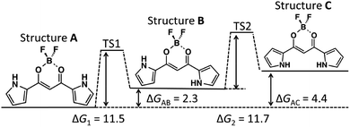 | ||
| Fig. 4 Potential diagram of 1 in CH2Cl2 (kcal mol−1). Values in the figure correspond to free energy. | ||
In the isomerization of complexes 1-X−, it should be important to discuss whether X− is captured with or without the rotation of the pyrrole ring. In the following part of this report, therefore, the rotations with or without the halide anion are denoted as “mechanism 1 with Cl−” or “mechanism 2 without Cl−,” respectively (see the graphical explanation in Fig. 5).
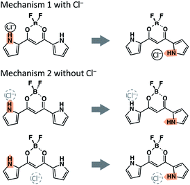 | ||
| Fig. 5 Two rotational mechanisms of the pyrrole ring. In mechanism 2, the position of the halide anion is not considered; Cl− may be located at site I, site II, or far from 1. | ||
The potential energy at each local minimum and TS of complex 1-Cl− is shown in Fig. 6. Here, we would like to focus on the mechanism from Structure A-I to C-II. The activation energy of the isomerization from Structure A-I to B-II is about 10.0 kcal mol−1, whereas that from A-II to B-II is about 11.9 kcal mol−1. As compared to the potential diagram of 1, the barrier of TS1 is lowered in mechanism 1 with Cl−. Cl−, therefore, leads to the rotation of the pyrrole ring to Structure B-II. On the other hand, the barrier height of TS2 shown in Fig. 6 is comparable to that of 1 shown in Fig. 4. Mechanism 2 without Cl−, therefore, has the same efficiency as that of 1.
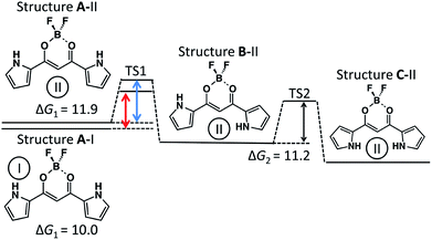 | ||
| Fig. 6 Potential diagram of 1-Cl− in CH2Cl2 (kcal mol−1). Values in the figure correspond to free energy. | ||
To analyze the isomerization mechanism from Structure A-I to C-II, Fig. 7 shows the interpolated two-dimensional potential energy surface (PES) of complex 1-Cl− in implicit CH2Cl2. In Fig. 7, the concerted rotation, where the two pyrrole rings rotate simultaneously, corresponds to the diagonal line from the left-bottom corner to top-right one. Since there is a fairly high barrier (about 24 kcal mol−1) in the central position in the PES, the directly concerted isomerization from Structure A-I to C-II should be fairly difficult. The stepwise isomerization mechanism from Structure A-I to C-II, therefore, is possible; Cl− moves from site I to site II with the first rotation of the pyrrole ring (i.e., isomerization via B-II); then, the second rotation occurs (i.e., isomerization via B-I). Mechanism 1 with Cl− has a higher potential barrier than mechanism 2 without Cl− for both the rotations, i.e., from A to B and from B to C. The barrier heights from A-I to C-II via B-I are 16 and 17 kcal mol−1 and the barrier heights from A-I to C-II via B-II are 15 and 13 kcal mol−1 from the potential energy of Structure C-II, respectively. Although the latter mechanism is slightly advantageous from the viewpoint of static DFT results, the competing reaction is expected because the bottlenecks in both the channels are comparable. Explicit solvent and countercation effect, therefore, should play an important role toward the elucidation of isomerization mechanism from Structure A-I to C-II.
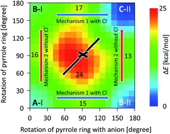 | ||
| Fig. 7 Interpolated two-dimensional PES of 1. The potential energies were calculated for 30° for each direction. The blue and red arrows show mechanism 1 with Cl− and mechanism 2 without Cl−, respectively. Numbers in the graph correspond to the potential energies at (0° and 90°), (90° and 0°), (180° and 90°), (90° and 180°), and (90° and 90°). Diagonal black arrow shows the concerted pyrrole ring rotation from Structure A-I to C-II. (The scatter plot without interpolation is shown in Fig. S13 in the ESI.†) | ||
4 Results and discussion regarding MD simulations
To elucidate the dynamical feature of the anion association mechanism from Structure A to C, MD simulations were performed for the systems composed of 1 and Cl− with several types of countercations in CH2Cl2.4.1 TBA cations
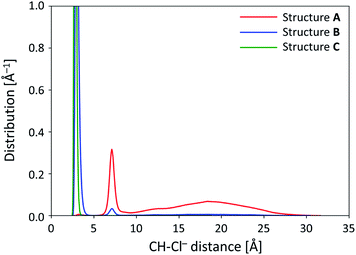
Fig. 8 shows the one-dimensional distributions of CH⋯Cl− distances for Structures A, B, and C, in order to specify the site where Cl− is captured. The peaks shown in Fig. 8 can be roughly categorized into 3 groups: sharp peak at around 4.0 Å, sharp peak at around 7.0 Å, and broad peak from 10 to 25 Å. The two sharp peaks (at around 4.0 and 7.0 Å) correspond to Cl− bound at site II and site I of 1, respectively. Since the peak from 10 to 25 Å is broad and the CH⋯Cl− distance is longer than those observed for the other 2 sharp peaks, this broad peak should be attributed to the Cl− free from 1. In Fig. 8, it is evident that the heights of the peaks are fairly different among Structures A, B, and C.Structure A (red line in Fig. 8) has a low peak at around 4.0 Å, sharp peak at around 7.0 Å, and broad peak from 10 to 25 Å. These peaks show that Cl− is bound at site I or free from 1, i.e., the dominant structure is A-I when 1 assumes Structure A. Unlike Structure A, Structure B (blue line in Fig. 8) has a major peak at around 4.0 Å and minor peak at around 7.0 Å. This suggests that both Structures B-I and B-II can exist; therefore, both the channels of isomerization from Structure A-I to both B-I and B-II can also exist. Furthermore, the height of distribution corresponding to Structure B-II is greater than that for Structure B-I, which supports that Cl− captured at site II can stabilize Structure B. The broad peak from 10 to 25 Å disappears in Structure B, which clearly shows that Cl− must be bound at site I or II when 1 assumes Structure B. This is consistent with the results obtained from our DFT calculations according to which Structure B-I was less stable than Structure B-II for 1, while more stable for complexes 1-X−. In Structure C (green line in Fig. 8), the peak at around 7.0 Å completely disappears, while both Structures B-I and B-II exist in Structure B. Therefore, Fig. 8 shows that Structure C-I and the isomerization channel from Structure C-I to C-II does not exist; this is consistent with our DFT calculation results.
Further, we note that the broad peak from 10 to 25 Å, corresponding to Cl− away from 1, disappears in both Structures B and C. From our DFT calculations, as shown in the earlier section, Structures B and C are less stable than Structure A for 1 and more stable for complexes 1-X−. The quenching of the broad peak in Fig. 8 indicates that Cl− should be bound at site I or site II when 1 assumes Structures B and C. Considering the existence of a major peak in Structure A at around 7.0 Å as well as the quenching of the broad peak, the anion-capturing mechanism can be considered to occur as follows. First, the anion is trapped at the shoulder (site I) of 1, and Structure A-I is generated. Then, the pyrrole ring rotates to yield Structure B-II; finally, another pyrrole ring inverts and the anion capture is completed. This can be described as mechanism 1 with Cl−, as shown in Fig. 5.
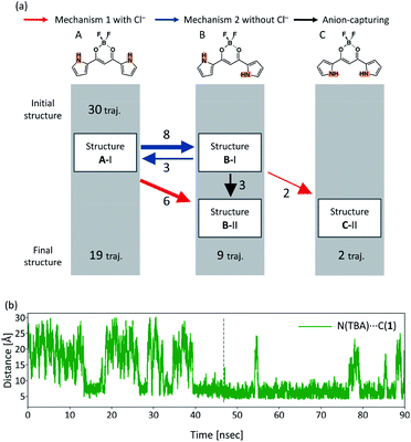
In order to see all the isomerization events that occur in all the 30 independent MD runs, Fig. 9(a) shows a summary of these isomerization events. In all the 30 independent MD runs, we set Structure A-I as the initial structure of 1. After executing the MD simulations for 90 ns, Structures A, B, and C were obtained within 19, 9, and 2 trajectories, respectively. The red and blue arrows in Fig. 9(a) indicate the isomerization events via mechanism 1 with Cl− and mechanism 2 without Cl−, respectively, as shown in Fig. 5, and the black arrow indicates the anion-capturing events without any rotation of the pyrrole rings. The overall events along the trajectories, therefore, can be classified into five patterns: (a) no reaction, (b) isomerization to B-I and back to A-I, (c) isomerization to C-II via B-I, (d) isomerization to B-I with Cl−, and (e) isomerization to B-II.
The isomerization events from Structure A-I to B-I and from Structure A-I to B-II occur 8 and 6 times, respectively. Reverse isomerization from Structure B-I to A-I, anion capture from Structure B-I to B-II, and second isomerization from Structure B-I to C-II occur 3, 3, and 2 times, respectively. While Structure B-I isomerizes into other structures, no isomerization occurs from Structure B-II. This result exhibits the relative stability of Structures B-I and B-II; Structure B-II is more stable than Structure B-I. It should be noted that the isomerization from Structure B-II to C-II, predicted by the DFT calculations, did not occur in the current MD simulations. This can be considered due to the size effect of the countercations, as discussed in the subsequent subsection.
To elucidate the relationship between the rotation of pyrrole rings and Cl− distances in the capturing process, Fig. S4† shows the time profile of the sum of the absolute value of two dihedral angles (ϕ1 and ϕ2) and the distance between CH and Cl− along the typical trajectories by means of red and blue curves, respectively. For Structures A, B, and C, the ϕ1 + ϕ2 values are smaller than 90°, between 90° and 270°, and more than 270°, respectively. Fig. S4† shows the typical trajectories to the five classes of the overall reactions discussed above. When 1 assumes Structure A (ϕ1 + ϕ2 < 90°), Cl− frequently approaches to and gets released from 1, where a change in the distance between CH and Cl− is independent of ϕ1 + ϕ2; this shows that these approaches are not caused by the change in the rotations of the pyrrole ring in Structure A. Structures B-I and B-II are shown in Fig. S4(b and e),† respectively. Structure B-I returns to Structure A-I within several nanoseconds, while Structure B-II does not isomerize into any other structure. Structure B-I, therefore, is less stable than Structure B-II. In Fig. S4(c),† the trajectory from Structure B-I to C-II is evident.
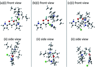
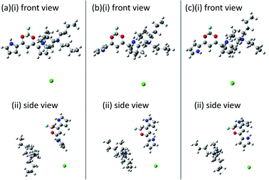
To visualize the position of TBA countercation, the snapshots of isomerization via mechanisms 1 and 2 in Fig. S4(b and e)† are shown in Fig. 10 and 11, respectively. In mechanism 1 with Cl−, as shown in Fig. 10, both the pyrrole ring and TBA rotate together. On the other hand, as shown in Fig. 11, only the pyrrole ring rotates in mechanism 2 without Cl−.
In order to discuss the reason why the isomerization from A-I to B-I occurs via mechanism 2 without Cl− while isomerization from B-II to C-II does not occur, Fig. 9(b) shows the time profile of the distance between the bridging carbon of the diketone of 1 and the nitrogen atom of TBA (Fig. S4(e)†), which can yield Structure B-II by mechanism 1 with Cl−. When 1 assumes Structure A-I, the distance between CH and Cl− frequently varies, as shown in Fig. S4.† On the other hand, the distance is almost constant after isomerization to Structure B-II. These results can be interpreted as the fact that complex 1-Cl− in Structure A-I can easily release the TBA and complex 1-Cl− in Structure B-II strongly attracts the TBA to formulate ion pairs of complex 1-Cl− and the cation. The facts that Structure A-I isomerizes into Structure B-I and Structure B-II does not isomerize into Structure C-II can be explained as follows. When complex 1-Cl− assumes Structure A-I, TBA is relatively free from the complex and therefore can isomerize into Structure B-I. Meanwhile, when complex 1-Cl− assumes Structure B-II, TBA is bound by the complex and therefore cannot isomerize into other structures.
4.2 TEA cations
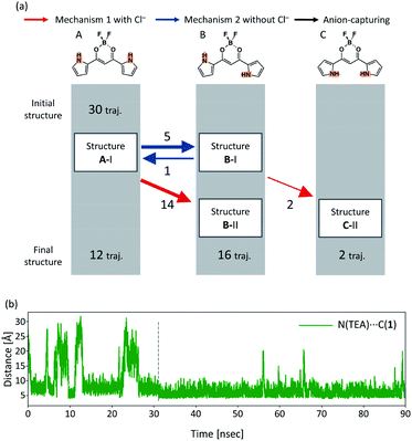
To discuss the size effect of the countercations, the MD simulation results with the TEA cation should be considered. Fig. 12(a) shows a summary of the total numbers of reactions in all the 30 independent MD runs with the TEA cation. After the MD simulations for 90 ns, Structures A, B, and C were obtained within 12, 16, and 2 trajectories, respectively. In Fig. 12(a), no anion-capturing events occur without any rotation of the pyrrole rings. The overall events along the trajectories in the TEA cation, therefore, can be classified into four patterns: (a) no reaction, (b) isomerization to B-I and back to A-I, (c) isomerization to C-II via B-I, and (d) isomerization to B-II. Similar to the case with the TBA cation, only Structure B-I can isomerize into Structure C-II; Structure B-II does not isomerize into any other structure. From the comparison of the number of events of isomerization, mechanism 1 with Cl− in the case of TEA is more advantageous than that in the case of TBA. In mechanism 1 with Cl−, the cation also moves with the rotation of the pyrrole ring of 1; therefore, the efficiency of mechanism 1 with Cl− should be affected by the countercation, as discussed in subsection 4.1.In order to elucidate how TEA interacts with 1 as well as the difference between the TEA and TBA countercations, Fig. 12(b) shows the distance between the bridging carbon of the diketone of 1 and the nitrogen atom of TEA. From the comparison of the data in Fig. 9(b) and 12(b), the distance of TEA in Fig. 12(b) is often found to be smaller than that of the TBA. In other words, the roaming of TEA in Structure B is more suppressed than that in the case of TBA. We focus on the difference between TEA and TBA on the efficiencies of the two isomerization mechanisms. In Fig. 12(a), isomerization from Structure A-I to B-II and isomerization from Structure B-I to C-II can be classified under mechanism 1 with Cl−. As compared to the case with TBA, the number of events of isomerization from Structure A-I to B-II increases. Although the number of isomerization events from Structure B-I to C-II is the same as that in the case of TBA, the number of isomerization events increases substantially because the isomerization from Structure A-I to B-I decreases and the chance to isomerize into Structure C-II is less than that in the case of TBA.
The isomerization from Structure A-I to B-I and reverse isomerization from Structure B-I to A-I were classified under mechanism 1 with Cl−. The number of these isomerizations is less than that observed in the TBA cation. Since the molecular size of TEA is smaller than that of TBA, the cation can approach to and can make strong interactions with 1. The strong interaction between 1 and the countercation blocks the rotation of the pyrrole ring, because the countercation needs to be away from 1 so that isomerization can occur via mechanism 2 without Cl−. The tight binding between 1 and TEA should decrease the chance of TEA dissociation from 1. Therefore, the size of TBA should be the reason for the suppression of mechanism 2 with Cl−.
The similarity of the final yield of Structure C-II between the TBA and TEA cases can be explained as follows. The first step that yields Structure B-I is less advantageous than the case of TBA. The second step that yields Structure C-II, however, is more advantageous than the case with TBA. Such a balance of the two reactions should afford comparable yields of C-II in this simulation.
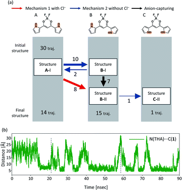
4.3 THA cations
A summary of all the 30 independent MD runs is shown in Fig. 13(a). After the MD simulations of 30 independent MD runs for 90 ns, Structures A, B, and C were obtained in 14, 15, and 1 trajectories, respectively. It should be noted that there is a direct channel from Structure B-II to C-II and no isomerization from Structure B-I to C-II only in the case of THA. The overall events along the trajectories, therefore, can be classified into four patterns: (a) no reaction, (b) isomerization to B-I and back to A-I, (c) isomerization to C-II via B-II, and (d) isomerization to B-II.The distance between the bridging carbon of the diketone of 1 and the nitrogen atom of the THA cation along a typical trajectory is shown in Fig. 13(b), revealing the relation between the rotation of the pyrrole ring and the location of the countercation. When Structure A isomerizes into Structure B-II, which is indicated by the first dashed line, the distance between the bridging carbon of the diketone of 1 and the THA cation is almost 20 Å. Fig. 13(b) shows that the cation is located away from 1 and the pyrrole ring does not rotate with the cation in the case of THA. This characteristic is unique to THA. Fig. 13(b) shows that the cation can be frequently released from 1; the interaction between THA and 1 is looser than those in the cases of TBA and TEA. From Fig. 13(b), it is evident that the distance between 1 and the cation is almost 20 Å at the moment when Structure B-II isomerizes into C-II (indicated by the second vertical dashed line), indicating that isolated 1 can isomerize into Structure C-II. The new isomerization channel from Structure B-II to C-II should be attributed to the difference in the character of the cation.
4.4 Na+ cations
A summary for the case of NaCl is shown in Fig. 14. In this figure, the blue arrows indicate the isomerization events via mechanism 2 without Cl−. Although the isomerization from Structure A-I to B-I is found, the entire portion of 1 in Structure B-I returns to Structure A-I at the end of the MD simulations. Fig. 14 shows that the isomerization via mechanism 1 with Cl− was not found in the case of Na+.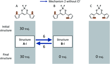 | ||
| Fig. 14 Events found in all the 30 independent MD runs in the case of Na+. The blue arrows correspond to isomerization by mechanism 2 without Cl−. | ||
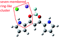
Fig. 15 shows a representative snapshot of the MD simulations for the system composed of 1 and NaCl. Cl− (indicated with a green sphere) is located near Na+ (indicated with a purple sphere), which is close to the oxygen atom (indicated with red spheres). Cl− is also located near the NH bonding of the pyrrole ring. It is important that a seven-membered ring cluster is formed among the Na+, Cl−, carbonyl group, and pyrrole ring, as shown in Fig. 15. Since the pyrrole ring near Cl− needs to be in the s-cis conformation in order to form such a seven-membered ring cluster, the structure in which the pyrrole ring is closer to Cl− than another pyrrole ring assumes the s-cis conformation, which is more stable than the structure with s-trans conformation. In fact, the pyrrole ring that is away from Cl− can rotate, while the pyrrole ring close to Cl− cannot rotate in all the isomerization events from Structure A-I to B-I. Since the isomerization from Structure B-I to C-I or C-II includes the rotation of the pyrrole ring, which is close to Cl− from s-cis conformer to s-trans conformer, the rotations from B-I to both C-I and C-II cannot be observed.
4.5 Absence of salts
A summary for the system without cations and Cl− is shown in Fig. 16. In this figure, the blue arrows indicate the isomerization events via mechanism 2 without Cl−. The overall events along the trajectories can be classified into four patterns: (a) no reaction, (b) isomerization to B and back to A, (c) isomerization to C and back to A via B, and (d) isomerization to B. After MD simulations of 30 independent MD runs for 90 ns, 1 assumes Structure B in only one trajectory and assumes Structure A in the remaining 29 trajectories.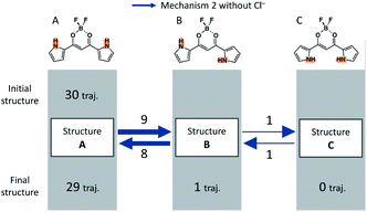 | ||
| Fig. 16 Events found in all the 30 independent MD runs in the absence of any salts. The blue arrows correspond to isomerization by mechanism 2 without Cl−. | ||
In the absence of salts, all the isomerization mechanisms can be classified into mechanism 2 without Cl− because there is no Cl−. Reverse isomerization channels from Structure B to A and Structure C to B exist, and stepwise reverse isomerization from Structure C to A occurs. We note that the reverse isomerization from Structure C to A can be found in the absence of any anions. This result suggests that Cl− plays a key role in the rotation of the pyrrole ring by stabilizing Structures B and C.
4.6 Effect of countercations
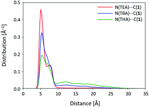
From the DFT calculations involving 1 (see Fig. 4 and 6), Structure A is observed to be the most stable in the case of no salt and Structure C is the most stable when the systems include salt. In the MD simulation results with no salt (subsection 4.5), it should be noted that many reverse isomerization processes occur from Structure B to A and reverse isomerization occurs from Structure C to B. This shows that Structures B and C are thermally less stable than Structures A and B, respectively, which is consistent with our DFT data. The calculated final ratio of each structure is in good agreement with the experimental data, wherein Structure A was found in the absence of anions. When Cl− is included in the system, Structures A, B, and C are classified into A-I and A-II, B-I and B-II, and C-I and C-II, respectively, as shown in Fig. 2. While Structure C of 1 is less stable than Structures A and B, Structure C-II of complex 1-Cl− is more stable than Structures A-I, A-II, and B-II (see Table 1 and Fig. 6). With respect to complex 1-Cl− as the anion moiety of the systems described earlier (subsections 4.1–4.4), Structure C-II is found to be the most stable structure for the corresponding systems.Focusing on the system with Cl−, the isomerization mechanism is classified into mechanism 1 with Cl− (red diagonal arrows) and mechanism 2 without Cl− (blue horizontal arrows) in Fig. 9(a), 12(a), 13(a), 14, and 15. From these figures, the number of isomerization events from Structure A-I to B-I via mechanism 2 without Cl− increases with the size of the cation, while isomerization from B-II to C-II is found to occur only in the largest countercation of THA. In order to elucidate how the cations are different from each other, we would like to focus on the distance between complex 1-Cl− and the cation. Fig. 17 shows the distribution of the distance between the bridging carbon of 1 and the nitrogen atom of the cations after isomerization to B-II. The distributions exhibit a peak at around 5 Å and a long tail from 10 to 30 Å. The height of the first peak decreases as the cation size increases, while the height of the tail increases with the cation size. Fig. 17 shows that a larger cation can be easily released from 1. Evidently, the salt comprising complex 1-Cl− with THA is more “soluble” than those with TBA or TEA. Furthermore, the time profile of the distance between 1 and the nitrogen atom of THA shown in Fig. 13(b) has more peaks than those in TBA (Fig. 9(b)) and TEA (Fig. 12(b)). This difference indicates that the release of the cation plays a key role in isomerization, i.e., isomerization occurs when the countercation is released from complex 1-Cl−. The reason why a large cation tends to get released from complex 1-Cl− is that the large cation cannot effectively approach the anions. Therefore, the electrostatic interaction between the large cation and anion is expected to become smaller than the interaction between the small cation and anion. In this simulation, therefore, the isomerization from B-II to C-II was found only in the system with THA, which is released from complex 1-Cl−. On the other hand, the systems with TBA or TEA also have the chance to isomerize into Structure C-II via mechanism 2 without Cl−. This should require a fairly long time for systems with TBA and TEA because the release of cations occurs less frequently than that in the case of THA.
From these results, the differences in the mechanism that affords Structure C-II can be explained as follows (schematically illustrated in Fig. S5†). From a strong peak (Fig. 17), both TBA and TEA cations get tightly bound to complex 1-Cl−. The cation is located near the central pocket of complex 1-Cl−. Because the interaction between complex 1-Cl− and THA is weaker than those with TBA and TEA, THA can be released from complex 1-Cl−, and it can give a chance for complex 1-Cl− to rotate into Structure C-II. As shown in Fig. 17, the binding of the cation becomes loose as the cation size becomes large; therefore, a large cation is advantageous for mechanism 2 without Cl−. The peaks shown in Fig. 9(b) and 12(b) indicate that both TBA and TEA should also have a chance to isomerize into Structure C-II via mechanism 2 without Cl−. In fact, Maeda and coworkers have experimentally reported that Structure C-II is the major conformation as the anion complex.5
Unlike TBA, TEA, and THA cations, Na+ can approach complex 1-Cl− quite closely, forming a cluster of complex 1-Cl− and Na+, since Na+ comprises a single atom. In order to reveal how Na+ interacts with complex 1-Cl−, the typical structure of the cluster composed of complex 1-Cl− and Na+ is shown in Fig. 15, which indicates that a seven-membered ring-like cluster is formed among Cl−, Na+, carbonyl group, and pyrrole ring at the left shoulder of 1. Since this cluster is rigid, the pyrrole ring bridged by Na+ cannot rotate. In fact, the pyrrole ring included in the cluster cannot rotate, while another pyrrole ring rotates in all the isomerization events. In addition, the isomerization from B-I to C-I or C-II is impossible because the direction of the pyrrole ring in the cluster is fixed by the ring-like cluster.
5 Conclusions
C-II of complex 1-Cl− shows that the barrier height of concerted rotation, where the two pyrrole rings rotate simultaneously, is about 24 kcal mol−1, while that of the stepwise isomerization via Structures B-I or B-II is about 16 kcal mol−1. The results of static DFT calculations clearly support that the latter stepwise mechanism via Structures B-I or B-II is advantageous for the isomerization of complex 1-Cl− from Structure A-I to C-II.Moreover, our MD results support stepwise isomerization. While Cl− stabilizes the system, a detailed mechanism of the isomerization of 1 depends on the type of countercations. When TBA or TEA are used as the countercations, Structure A-I isomerizes into Structure C-II via Structure B-II. On the other hand, when THA is used, isomerization occurs via Structure B-I rather than that via Structure B-II. From these MD trajectories, we can conclude that a large cation (such as THA) gets released from 1 more frequently than those in the cases with the smaller cations of TBA or TEA. Because THA can be released from 1, the isomerization from Structure B-II to Structure C-II occurs. Meanwhile, NaCl forms a seven-membered ring-like cluster with 1, and isomerizations from Structure B-I to both C-I or C-II get suppressed. Hence, from our MD simulations, it is evident that the size of the cation influences the isomerization process. From the experimental viewpoint, the solubility of salts controls the isomerization mechanism.
Conflicts of interest
There are no conflicts to declare.Acknowledgements
This work is partly supported by Grants-in-Aid for Scientific Research (KAKENHI) of the Ministry of Education, Culture, Sports, Science and Technology (MEXT), Grant Numbers JP18H01945, JP19H05063, JP19H05155 for MT, and JP26288042, JP18H01968 for HM. The computations were partly performed using Research Center for Computational Science (RCCS), Okazaki, Japan.Notes and references
- (a) Anion Sensing, Topics in Current Chemistry, ed. I. Stibor, Springer, Berlin, 2005, vol. 255 Search PubMed; (b) J. L. Sessler, P. A. Gale and W.-S. Cho, Anion Receptor Chemistry, RSC, Cambridge, 2006 Search PubMed; (c) Anion Recognition in Supramolecular Chemistry, Topics in Heterocyclic Chemistry, ed. P. A. Gale and W. Dehaen, Springer, Berlin, 2010, vol. 24 Search PubMed.
- (a) K.-J. Chang, B.-N. Kang, M.-H. Lee and K.-S. Jeong, J. Am. Chem. Soc., 2005, 127, 12214–12215 CrossRef CAS PubMed; (b) H. Juwarker, J. M. Lenhardt, D. M. Pham and S. L. Craig, Angew. Chem., Int. Ed., 2008, 47, 3740–3743 CrossRef CAS PubMed; (c) R. M. Meudtner and S. Hecht, Angew. Chem., Int. Ed., 2008, 47, 4926–4930 CrossRef CAS PubMed; (d) Y. Hua and A. H. Flood, J. Am. Chem. Soc., 2010, 132, 12838–12840 CrossRef CAS PubMed; (e) J.-m. Suk, V. R. Naidu, X. Liu, M. S. Lah and K.-S. Jeong, J. Am. Chem. Soc., 2011, 133, 13938–13941 CrossRef CAS PubMed; (f) W. Zhao, Y. Wang, J. Shang, Y. Che and H. Jiang, Chem.–Eur. J., 2015, 21, 7731–7735 CrossRef CAS PubMed; (g) F. C. Parks, Y. Liu, S. Debnath, S. R. Stutsman, K. Raghavachari and A. H. Flood, J. Am. Chem. Soc., 2018, 140, 17711–17723 CrossRef CAS PubMed.
- H. Juwarker, J.-m. Suk and K.-S. Jeong, Chem. Soc. Rev., 2009, 38, 3316–3325 RSC.
- G. I. Vargas-Zúñiga and J. L. Sessler, Coord. Chem. Rev., 2017, 345, 281–296 CrossRef PubMed.
- H. Maeda and Y. Kusunose, Chem.–Eur. J., 2005, 11, 5661–5666 CrossRef CAS PubMed.
- Selected reviews on anion-responsive acyclic π-electronic molecules: (a) H. Maeda, Bull. Chem. Soc. Jpn., 2013, 86, 1359–1399 CrossRef CAS; (b) Y. Haketa and H. Maeda, Chem. Commun., 2017, 53, 2894–2909 RSC; (c) Y. Haketa and H. Maeda, Bull. Chem. Soc. Jpn., 2018, 91, 420–436 CrossRef CAS.
- (a) Y. Haketa, S. Sasaki, N. Ohta, H. Masunaga, H. Ogawa, N. Mizuno, F. Araoka, H. Takezoe and H. Maeda, Angew. Chem., Int. Ed., 2010, 49, 10079–10083 CrossRef CAS PubMed; (b) H. Maeda, K. Naritani, Y. Honsho and S. Seki, J. Am. Chem. Soc., 2011, 133, 8896–8899 CrossRef CAS PubMed; (c) B. Dong, T. Sakurai, Y. Honsho, S. Seki and H. Maeda, J. Am. Chem. Soc., 2013, 135, 1284–1287 CrossRef CAS PubMed; (d) B. Dong, T. Sakurai, Y. Bando, S. Seki, K. Takaishi, M. Uchiyama, A. Muranaka and H. Maeda, J. Am. Chem. Soc., 2013, 135, 14797–14805 CrossRef CAS PubMed; (e) R. Sekiya, Y. Tsutsui, W. Choi, T. Sakurai, S. Seki, Y. Bando and H. Maeda, Chem. Commun., 2014, 50, 10615–10618 RSC; (f) V. Lakshmi, Y. Haketa, R. Yamakado, N. Yasuda and H. Maeda, Chem. Commun., 2017, 53, 3834–3837 RSC.
- (a) Y. Haketa and H. Maeda, Chem.–Eur. J., 2011, 17, 1485–1492 CrossRef CAS PubMed; (b) Y. Haketa, Y. Bando, K. Takaishi, M. Uchiyama, A. Muranaka, M. Naito, H. Shibaguchi, T. Kawai and H. Maeda, Angew. Chem., Int. Ed., 2012, 51, 7967–7971 CrossRef CAS PubMed.
- A. D. Becke, J. Chem. Phys., 1997, 107, 8554–8560 CrossRef CAS.
- J.-D. Chai and M. Head-Gordon, J. Chem. Phys., 2008, 128, 84106 CrossRef PubMed.
- (a) G. A. Petersson, A. Bennett, T. G. Tensfeldt, M. A. Al-Laham, W. A. Shirley and J. Mantzaris, J. Chem. Phys., 1988, 89, 2193–2218 CrossRef CAS; (b) G. A. Petersson and M. A. Al-Laham, J. Chem. Phys., 1991, 94, 6081–6090 CrossRef CAS.
- S. Miertus, E. Scrocco and J. Tomasi, Chem. Phys., 1981, 55, 117–129 CrossRef CAS.
- M. J. Frisch, G. W. Trucks, H. B. Schlegel, G. E. Scuseria, M. A. Robb, J. R. Cheeseman, G. Scalmani, V. Barone, B. Mennucci, G. A. Petersson, H. Nakatsuji, M. Caricato, X. Li, H. P. Hratchian, A. F. Izmaylov, J. Bloino, G. Zheng, J. L. Sonnenberg, M. Hada, M. Ehara, K. Toyota, R. Fukuda, J. Hasegawa, M. Ishida, T. Nakajima, Y. Honda, O. Kitao, H. Nakai, T. Vreven, J. A. Montgomery, Jr, J. E. Peralta, F. Ogliaro, M. Bearpark, J. J. Heyd, E. Brothers, K. N. Kudin, V. N. Staroverov, T. Keith, R. Kobayashi, J. Normand, K. Raghavachari, A. Rendell, J. C. Burant, S. S. Iyengar, J. Tomasi, M. Cossi, N. Rega, J. M. Millam, M. Klene, J. E. Knox, J. B. Cross, V. Bakken, C. Adamo, J. Jaramillo, R. Gomperts, R. E. Stratmann, O. Yazyev, A. J. Austin, R. Cammi, C. Pomelli, J. W. Ochterski, R. L. Martin, K. Morokuma, V. G. Zakrzewski, G. A. Voth, P. Salvador, J. J. Dannenberg, S. Dapprich, A. D. Daniels, O. Farkas, J. B. Foresman, J. V. Ortiz, J. Cioslowski and D. J. Fox, Gaussian 09 (Revision D.01), Gaussian, Inc., Wallingford CT, 2013 Search PubMed.
- D. A. Case, R. M. Betz, D. S. Cerutti, T. E. Cheatham, III, T. A. Darden, R. E. Duke, T. J. Giese, H. Gohlke, A. W. Goetz, N. Homeyer, S. Izadi, P. Janowski, J. Kaus, A. Kovalenko, T. S. Lee, S. LeGrand, P. Li, C. Lin, T. Luchko, R. Luo, B. Madej, D. Mermelstein, K. M. Merz, G. Monard, H. Nguyen, H. T. Nguyen, I. Omelyan, A. Onufriev, D. R. Roe, A. Roitberg, C. Sagui, C. L. Simmerling, W. M. Botello-Smith, J. Swails, R. C. Walker, J. Wang, R. M. Wolf, X. Wu, L. Xiao and P. A. Kollman, AMBER 2016, University of California, San Francisco, 2016 Search PubMed.
- J. Wang, R. M. Wolf, J. W. Caldwell, P. A. Kollman and D. A. Case, J. Comput. Chem., 2004, 25, 1157–1174 CrossRef CAS PubMed.
- C. I. Bayly, P. Cieplak, W. Cornell and P. A. Kollman, J. Phys. Chem. B, 1993, 97, 10269–10280 CrossRef CAS.
- J. A. Maier, C. Martinez, K. Kasavajhala, L. Wickstrom, K. E. Hauser and C. Simmerling, J. Chem. Theory Comput., 2015, 11, 3696–3713 CrossRef CAS PubMed.
- C. Caleman, P. J. van Maaren, M. Hong, J. S. Hub, L. T. Costa and D. van der Spoel, J. Chem. Theory Comput., 2012, 8, 61–74 CrossRef CAS PubMed.
- J. de Andrade, E. S. Boes and H. Stassen, J. Phys. Chem. B, 2002, 106, 13344–13351 CrossRef CAS.
- R. J. Loncharich, B. R. Brooks and R. W. Pastor, Biopolymers, 1992, 32, 523–535 CrossRef CAS PubMed.
- T. Darden, D. York and L. Pedersen, J. Chem. Phys., 1993, 98, 10089–10092 CrossRef CAS.
Footnote |
| † Electronic supplementary information (ESI) available. See DOI: 10.1039/c9ra09285d |
| This journal is © The Royal Society of Chemistry 2020 |

