 Open Access Article
Preparation of high-strength and lightweight microcellular polysulfone foam with a segregated CNT network for excellent electromagnetic shielding†
Yeping Xiea,
Fan Yea,
Wenhua Chenbc,
Jiahong Tanga and
Pengju Liu *ad
*ad
aState Key Laboratory of Polymer Materials Engineering, Polymer Research Institute of Sichuan University, Chengdu, 610065, China. E-mail: sculpj@163.com
bCollege of Architecture and Environment, Sichuan University, Chengdu, 610065, China
cNational Engineering Research Centre for Flue Gas Desulfurization, Chengdu, 610065, China
dJieshou Tianhong New Material Co., Ltd, Jieshou, 236500, China
First published on 24th March 2020
Abstract
Fabrication of microcellular polymer composite foam based on high-performance plastic is a promising strategy for preparing the lightweight, high-strength and multifunctional materials. Herein, we proposed a facile and green method to prepare microcellular polysulfone/carbon nanotube (PSU/CNTs) composite foams with segregated structure by combining solid-phase milling and supercritical carbon dioxide (scCO2) foaming. The segregated PSU/CNTs foam with as low as 5.0 wt% CNT was provided with a good electrical conductivity of 5.2 S m−1 and an acceptable electromagnetic interference shielding effectiveness (EMI SE) of 23.7 dB, respectively. Moreover, the segregated PSU/CNT foam exhibited an ultralow percolation threshold of 0.06 vol%. An absorption-dominant shielding feature was observed for segregated PSU/CNT foam, which could be attributed to the synergistic effect of the perfect CNT networks and the microcellular structure in PSU domains. In addition, benefitting from the inherent properties of the PSU matrix, foam density dropped to 0.69 g cm−3, and the material still possessed a high specific compression strength of 38.8 MPa cm3 g−1. Therefore, our work provided an insight into the preparation of lightweight, high-strength and multifunctional materials that might have great potential applications in aerospace and military areas.
1. Introduction
Over the past 10 years, the rapid rise of the information technology, especially the explosive advance of portable devices has brought convenience to our lives. However, it also causes serious electromagnetic (EM) pollution invisibly, which not only obstructs the normal use of electronic equipment but also does great harm to human health as well as national defense security.1–4In contrast to the traditional metallic shielding materials, conductive polymer composites (CPCs) show significant advantages for electromagnetic interference (EMI) shielding, due to their unique characteristics, including lightweight, tunable electrical conductivity, resistance to corrosion, and good processability.5–13 As is known to all, the value of electromagnetic interference shielding effectiveness (EMI SE) over 20 dB is a general requirement for CPCs materials to meet the commercial application.14–16 In order to achieve this target, a high content of conductive fillers have to be incorporated into the electrically insulated polymer matrix. However, this in turn results in higher cost, deteriorated processability and degraded mechanical performance.17–19 Recently, constructing a segregated structure, differing from the traditional melt blending and solution mixing, has been widely recognized as an efficient strategy to enhance the electrical conductivity and EMI SE of the CPCs at a relatively low conductive filler loading.20–28 For segregated CPCs, the conductive fillers are selectively located at the interfacial regions rather than scattering over the whole system, and thus the conductive networks are readily constructed along the polymer surface.29,30 Zhang et al.31 comparatively evaluated the EMI SE of extrusion blended and segregated PPS/CNT composite, and investigated the critical role of the segregated network for enhancement in the shielding performance. The results showed that the segregated PPS/CNT composite with only 5.0 wt% CNTs was provided with a high EMI SE value of 49.6 dB and electrical conductivity of 72.0 S m−1, while a low EMI SE of 24.9 dB was observed for the extrusion blended composite with an equal amount of CNTs. However, a significant increase in the reflected power coefficient always occurs, which can be attributed to the impedance mismatch at interfacial regions between air and CPCs.32–34 This reflection dominant mechanism makes CPCs unsuitable for some specific applications where EMI shielding is required rather than generating the secondary EM reflections. The reflected EM wave caused by shielding materials will cause severe adverse effects on the neighboring devices and circuits.
Structural design of polymer composites is an efficient strategy for improving the material's properties and has attracted increasing attention from academic and industrial researchers. Porous CPCs, fabricated by foaming technology, are regarded as new alternative candidates for EMI shielding because of lightweight and absorption-dominated shielding mechanism by incorporating air phase.35–39 Moreover, the massive interfaces existing in the porous CPCs can improve the EMI SE by multiple scatterings and reflections, and thus consuming the energy of electromagnetic waves ultimately.40,41 So far, the porous CPCs with segregated conductive network is seldom reported.
Recently, polymer foams are mainly based on the general plastics, including polystyrene, polyethylene, polyurethane, polyvinyl chloride, etc. However, these conventional polymer foams suffer from the unsatisfactory performance limited by their inherent characteristics, which cannot meet the special requirements in aerospace and other high-end applications. Alternatively, polysulfone (PSU), as a typical special engineering plastic, has the excellent comprehensive performance, including intrinsic flame retardancy, good chemical resistance, high heat resistance and mechanical strength.42 However, to our knowledge, few studies have been conducted on the preparation of PSU and PSU-based foams because of the high processing temperature (270–300 °C). Thus, some advanced methods should be developed to prepare the lightweight PSU-based foams with high-strength and multifunction, which will facilitate the potential applications in widespread fields.
To solve the above issues, a novel and green strategy was proposed in this study to prepare the high-performance PSU/CNTs composite foams, including the construction of segregated CNTs network in PSU composites through solid-phase milling, and then creating microcellular structure in PSU domains by scCO2 foaming. The prepared PSU/CNTs composite foams were endowed with the high electrical conductivity, EMI shielding and mechanical strength, showing a huge potential to meet some specific application in the harsh environment. Moreover, the porous segregated CPCs display an absorption dominant EMI shielding mechanism, which is more suitable for applications where the secondary reflection should be avoided as much as possible.
2. Experimental section
2.1. Materials
PSU particles with the size range from 150 to 250 μm were supplied by Suyu Plastic Co., Ltd (Shanghai, China). CNTs (NC7000, Belgium) with the average diameter of 9.5 nm and length of 1.5 μm were purchased from Nanocyl S.A. CO2 was provided by Chengdu Xuyuan Co., Ltd., with the purity around 99.5%.2.2. Fabrication of the PSU/CNTs composite foams
The fabrication of the segregated PSU/CNTs composite foam is shown in Fig. 1. Firstly, CNTs and PSU particles were mixed in a ball milling machine (QM-3SP4, Nanjing Nanda instrument Co., Ltd, China) for 1 h with a speed of 500 rpm to prepare CNTs coated PSU complex particles. Then, the complex particles were molded into a PSU/CNTs composite at 320 °C for 15 min, under a pressure of 10 MPa. The segregated PSU/CNTs composites (denoted as s-PC) with various CNTs contents of 0.1, 0.5, 1.0, 3.0, and 5.0 wt% were prepared. For convenient, composite samples with different CNTs content were defined as s-PC-0.1, s-PC-0.5, s-PC-1, s-PC-3, s-PC-5. As a comparison, the conventional extruding PSU/CNTs composite (denoted as e-PC) with CNTs fillers distributed randomly in PSU matrix was obtained. PSU and CNTs were mixed in a HAAKE internal mixer (150 rpm, 20 min) and molded at 320 °C and 10 MPa for 10 min. After saturated by scCO2 (14 MPa and 170 °C) in a high-pressure vessel for 90 min, the PSU/CNTs composite foams (denoted as s-PCF or e-PCF) were ultimately prepared by rapid depressurization (5 MPa s−1). It should be noted that the s-PCF-5 with different mean densities of 0.86, 0.69 and 0.48 g cm−3 were obtained through changing the foaming temperature, including 165, 170 and 175 °C, and the related parameters, including apparent density and expansion ratio were listed in Table 1. Due to relatively low loading, the addition of CNTs almost had little effect on the final foam density.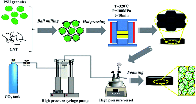 | ||
| Fig. 1 Illustration showing the fabrication process of the PSU/CNT composite foams with segregated structure. | ||
| CNTs content in foamed samples (wt%) | Apparent density (g cm−3) | Expansion ratio | Foaming temperature (°C) |
|---|---|---|---|
| 1 | 0.83 | 1.49 | 165 |
| 0.65 | 1.84 | 170 | |
| 0.45 | 2.68 | 175 | |
| 3 | 0.84 | 1.50 | 165 |
| 0.68 | 1.85 | 170 | |
| 0.47 | 2.72 | 175 | |
| 5 | 0.86 | 1.47 | 165 |
| 0.69 | 1.83 | 170 | |
| 0.48 | 2.63 | 175 |
2.3. Characterizations
The morphologies of PSU particles coated with CNTs, the fractured surfaces of solid and foamed PSU composites were studied using the SEM equipment (Inspect F, FEI) at 0.5 torr and 15 kV. The liquid nitrogen was used to freeze the samples' structure and they were fractured immediately and covered with Au coating. The mean pore size was calculated by analyzing the SEM images through the software Nano-Measurer. In order to observe the segregated structure more prominently, the solid s-PC samples were cut into a thin film with a thickness of 20 μm through the microtome and the translucent film was inspected through an optical microscope (Leica DM2500P) with a Micro-Publisher 3.3 RTV CCD camera. The densities of PC (ρ) and PCF (ρf) were conducted on an automatic density instrument (MDMDY-350, Meidi analytical Co., Ltd., China). The electrical conductivities of the s-PC with 1.0, 3.0, and 5.0 wt% CNTs and the e-PC composites with 3.0 and 5.0 wt% CNTs as well as s-PCF with 3.0, and 5.0 wt% CNTs were investigated using a four-point probe instrument (RK-FA, Ningbo Ruikeweiye instrument Co., Ltd, China). The other samples with low CNTs loading were measured by a Fluke 15 B+ digital multimeter (Fluke, USA). In order to eliminate the effect of the contact resistance, the cross-sectional of the circular sample was coated with a thin layer of silver. The electrical conductivity was calculated using the equation σ = L(SR), where σ and R represent the electrical conductivity and electrical resistance, and L and S represent the length and cross-sectional area of the circular sample. For the electrical conductivity test, compact samples were prepared in a circular column with a diameter of 13 mm and a height of 2 mm and the foam samples were measured directly. In all cases, two measurements were performed for each sample and 5 samples for each PSU/CNTs composite were prepared, last, the average values were obtained. The EMI shielding performance of the PSU/CNTs composites and foams in the X-band frequency (8.2–12.4 GHz) was measured using a high-performance network analyzer (Agilent N5247A) connected with a coaxial test cell (APC-7 connector). The sample is in the disk shape with the thickness of 2.0 mm and diameter of 13.0 mm. At least five sample replications were performed for each case, and the average values were reported. The reflected power coefficient (R), absorption power coefficient (A), transmitted power coefficient (T), as well as microwave reflection shielding (SER) and microwave absorption shielding (SEA) were obtained by calculating the scattering parameters (S11 and S21) using the following equations.43| R = |S11|2 | (1) |
| T = |S21|2 | (2) |
SER = −10![[thin space (1/6-em)]](https://www.rsc.org/images/entities/char_2009.gif) lg(1 − R) lg(1 − R)
| (3) |
SEA = −10![[thin space (1/6-em)]](https://www.rsc.org/images/entities/char_2009.gif) lg(T/(1 − R)) lg(T/(1 − R))
| (4) |
| SETotal = SEA + SER + SEM | (5) |
Among them, when SETotal is greater than 10 dB, microwave multiple internal reflections (SEM) can be ignored.25 Compression property of s-PCF was tested using a universal machine (Instron 5567, Instron Co., Ltd., United States). Foamed samples were prepared from a solid sample with a diameter of 16 mm and a height of 3 mm. After foaming, the slight change of diameter and obvious increase of height were observed in all foamed samples, as shown in Fig. S1.† Then the foamed sample were cut into 3 mm in height using a sharp knife used for compression testing, and the crosshead speed was 5 mm min−1.
3. Results and discussion
3.1. Morphology and microstructure
The morphologies of PSU granules coated with CNTs are shown in Fig. 2a. PSU granules are irregular-like granules with an average diameter of 190 μm. From the inset image in Fig. 2a, CNTs fillers are homogeneously and tightly enriched on the surface of the PSU particles, which will facilitate the construction of perfect conductive networks in the subsequent processing and foaming steps. In order to give an intuitive insight into the conductive pathways and identify the formation of conductive networks in the s-PC, the fractured surface and detailed microstructure of the s-PC-5 was further investigated by SEM observation. From Fig. 2b, massive CNTs are squeezed among the interfacial regions and joint the neighboring PSU domains, clearly indicating the formation of the perfect segregated network. The magnified image (inset in Fig. 2b) reveals the directive enrichment of CNT along the boundaries of the PSU domains.44 Moreover, the OM observation was also used to confirm the successful establishment of perfect segregated structure in a further vivid manner and the related photo is displayed in Fig. 2c. As expected, we can find a honeycomb-like structure in this photo where the continuous CNTs phases (dark line) surround the isolated PSU domains (bright regions). When the CNTs loading is as low as 0.5 wt%, the interconnected conductive network is constructed (Fig. S2†), and the conductive CNTs pathways become denser and thicker with the increase of CNTs content. The unique segregated conductive networks dramatically improve the utilization efficiency of CNTs and are promising to fabricate PSU/CNTs composite foams with good electrical conductivity and EMI shielding performance.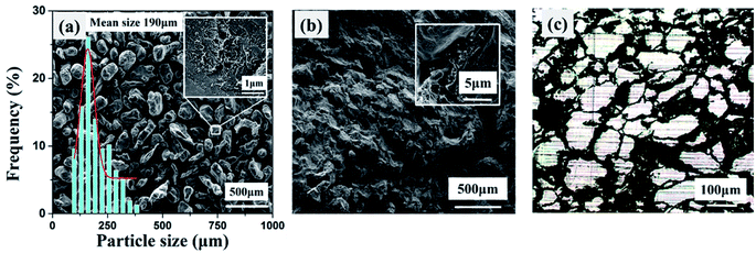 | ||
| Fig. 2 SEM images of (a) PC-5 complex granules (inset is the magnified SEM image); (b) cryo-fractured surface of the (inset is the magnified SEM image); (c) OM image of the s-PC-5 slice. | ||
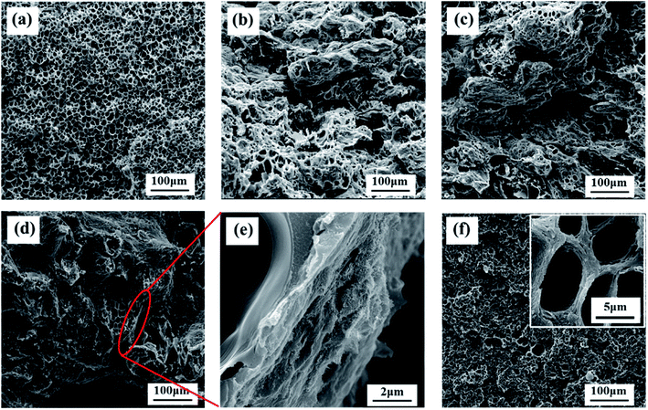
Fortunately, after foaming by scCO2, the original segregated conductive networks still exist in the interface of PSU granules and only with slight damage. What's more interesting is that s-PCF show the similar cellular structure with the PSU foams because the CNTs selectively distribute on the surface of PSU particles and do not act as the heterogeneous nucleation sites.45 In contrast, the cell size of e-PCF is smaller than that of s-PCF. According to the classical nucleation theory, the introduction of CNTs can significantly increase the nucleation sites, in addition, well-dispersed CNTs also improve the melt strength of PSU matrix resins.46–48 As shown in Fig. 3b, the CNTs are distributed in each cellular wall and the random distribution of CNTs greatly reduces their utilization efficiency. As a result, e-PCF will be provided with much lower the electrical performance and EMI SE property than s-PCF. Besides, the pore size distributions of PCF with different CNTs content were determined by statistic software and plotted in Fig. 4. The values of the mean pore size of the pure PSU and segregated composite foams range from 8.8 to 11.6 μm. As expected, e-PCF-5 presents smaller pores with a mean size of 6.8 μm, which is due to the significant heterogeneous nucleation of CNTs.
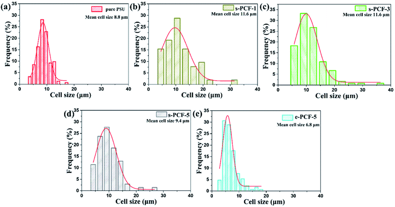 | ||
| Fig. 4 Cell size distribution of PSU and PSU/CNTs composite foams prepared at the same condition of 14 MPa and 165 °C: (a) pure PSU foam; (b) s-PCF-1; (c) s-PCF-3; (d) s-PCF-5; (e) e-PCF-5. | ||
3.2. Electrically conductive and EMI shielding performance
Achieving a good EMI shielding property is urgently needed for the commercialization of materials in aerospace and electronics industry applications. As we all know, the EMI shielding of CPCs is tightly related to their electrical conductivities.15,20,22 Fig. 5a illustrates the electrical conductivity of solid and foamed segregated PSU/CNTs composites with various CNTs loadings. Continuous improvement in electrical conductivity is observed with increasing CNTs content. Both PSU/CNTs composites and foams present the typical percolation behavior, for example, a sharp variation of nearly 9 orders of magnitude in electrical conductivity for solid PSU/CNTs composites with CNTs loading increasing from 0.1 to 0.25 wt%. For comparison, the conductive performance of solid and foamed e-PC with randomly distributed CNTs were also investigated (shown in Fig. S3†). The electrical conductivity of the s-PC is far superior to that of e-PC at the same CNTs loading. For instance, the electrical conductivity of s-PC-3 reached 6.9 S m−1, much higher than 1.0 S m−1 that is the target value satisfied with commercial EMI shielding applications. When the loading of CNTs increases to 5 wt%, an excellent electrical conductivity value of 35.4 S m−1 is achieved, while the electrical conductivity of e-PC-5 is as low as 2.6 S m−1. After foaming by scCO2 technology, the foamed segregated PSU/CNTs composite is provided with a declined electrical conductivity than solid composite, which can be attributed to the damaged CNTs network caused by cellular structure formed in PSU domains. It was reported that incorporating cellular structure could enhance the electrical conductivity of CPCs due to the rearrangement of conductive fillers in cell walls.49,50 But cell size of the cellular structure generated in PSU/CNTs composite is in the range of several to tens of microns, much larger than the dimensions of CNTs filler, and thus no alignment of CNTs occurs during the foaming process. Fortunately, the electrical conductivity of s-PCF-5 (with an expansion ratio of 1.44) is kept at the high level of 5.2 S m−1, which is much higher than that of e-PCF-5 (0.016 S m−1). In this way, it can be concluded that selective distribution of CNTs in the interfacial regions is a more efficient strategy for constructing the conductive network than random distribution in polymer matrix, and this unique network can be well maintained even in the subsequent foaming procedure.Fig. 5b and c show EMI SE of the PSU/CNTs composites and foams as a function of CNTs loading in the X-band (8.2–12.4 GHz). It can be clearly seen from Fig. 5b the s-PC exhibit a gradually enhanced EMI SE with an increase in CNTs content. Higher loading of CNTs induces a larger number of free electrons, which not only improves the electrical conductivity but also attenuates the incident electromagnetic waves inside the segregated PSU/CNTs composite. The segregated composite containing 5.0 wt% CNTs is provided with the excellent EMI shielding performance and with the shielding effectiveness as high as 41 dB. As expected, resulting from the negative effect of foaming on electrical conductivity, a declined EMI shielding property was observed in the s-PCF. For example, the EMI SE of s-PCF-5 is decreased to 23.7 dB due to the partial damage on the original CNTs network after foaming. However, the conventional extruded composite foams show obviously decreased EMI SE and only 10.4 dB is obtained for e-PCF-5. As we mentioned above that the foaming process will unavoidably weaken the electrical conductivity and EMI shielding performance of segregated composites. However, benefit from CNTs fillers enriching on the interfaces among porous PSU domains, the segregated composite foams exhibit significant advantages over the traditional composite foams with randomly distributed CNTs. Therefore, the unique porous segregated structure we constructed in CPCs is practicable for preparing multifunctional composite foams with the satisfactory conductive and EMI shielding performance. From the data listed in Table 2, the expansion ratio (i.e. foam density) has a great effect on the EMI shielding performance of foamed sample. The EMI SE value of s-PCF-5 declined from 23.7 to 15.6 dB with its apparent density decreasing from 0.86 to 0.48 g cm−3. Moreover, the specific EMI SE, calculated by the ratio of EMI SE and apparent density, was proposed to evaluate the shielding property of the foamed materials. The s-PCF-5 with apparent density of 0.48 g cm−3 had a specific EMI SE value of 32.5 dB cm3 g−1, which was basically at the same level as the solid s-PC-5 composite.
| Sample | Apparent density (g cm−3) | EMI SE (dB) | Specific EMI SE (dB cm3 g−1) | Specific compression stress (MPa cm3 g−1) |
|---|---|---|---|---|
| s-PC-5 | 1.27 | 41.2 | 32.4 | — |
| s-PCF-5 | 0.86 | 23.7 | 27.6 | 36.4 |
| 0.69 | 19.8 | 28.7 | 38.8 | |
| 0.48 | 15.6 | 32.5 | 22.1 |
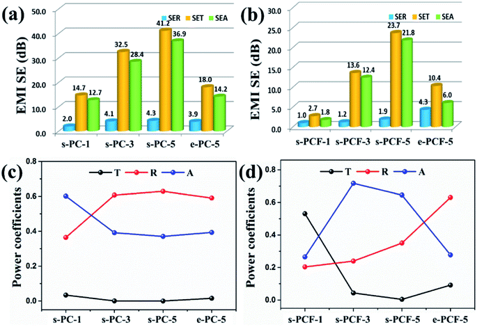
To better understand and further enhance the EMI shielding behavior of the composites with porous segregated structure, it is necessary to analyze the main EMI shielding mechanism including absorption and reflection. Thus, the contributions of SEA and SER to EMI SE of the solid and foamed PSU/CNTs at the specific frequency of 10.0 GHz are determined by the scattering parameters (Fig. 6a and b). Apparently, for both composites and foams, SEA raises significantly with the increase in CNTs loading, and SER fluctuates slightly. Meanwhile, SEA is much larger than SER among all samples. This result distinctly conforms an absorption-dominated shielding rather than reflection mechanism, mainly due to the generation of the unique segregated network. For instance, SEA and SER of the s-PC-5 are 36.9 and 4.3 dB at 10.0 GHz, respectively, which means that the absorption shielding contributes a much larger proportion (89.6%) than the reflection shielding. For comparison, the EMI SE of the e-PC-5 with randomly distributed CNTs was also investigated. The SEA and SER of the e-PC-5 are 14.2 and 3.9 dB at 10.0 GHz, respectively, indicating the contribution of absorption is only 78.5%. After foaming, the samples with porous segregated structure show the further increased ratio of SEA/SET (92.1%), while the ratio of the foamed sample with randomly dispersed CNTs is as low as 58.3%. In a word, integrating the cellular structure with CNTs conductive networks will significantly enhance the ability of porous segregated materials to absorb EM waves.
Considering that SEA and SER only represent the capability of shielding electromagnetic waves that can enter materials, and it is also needed to study the transfer behavior of EM wave incident on the material surface. Fig. 6c and d show the power coefficient (including T, R, and A) of the solid and foamed PSU/CNTs composites as a function of CNTs content. The variation in the power coefficient of segregated composites before and after foaming was comparatively studied. For the solid sample, T changes slightly with the increase of CNTs content, and R experiences a significant enhancement with CNTs loading rising to 3 wt%, which is due to the impedance mismatch at interfaces caused by the relatively high conductivity of s-PC. After foaming, a slight change is observed in T, except for the sample containing 1 wt% CNTs with low electrical conductivity. The value of R decreases greatly because of the resistance reduction caused by the introduction of cellular structure. In this way, EM waves can easily enter into the interior of the samples and along with a small fraction of reflections on their surface. The unique porous segregated structure, combining the micropores and CNTs networks can greatly facilitate the incident microwaves to be absorbed and followed by converting into thermal energy through the multiple reflections and scatterings on the multi-level interfaces of the CNTs conductive networks and cellular walls.
In addition, a comparative study of samples with randomly distributed and segregated CNTs was also conducted. Before foaming, the values of A, T, and R are almost the same, while the segregated foams are provided with the higher A than the randomly distributed one after foaming. Meanwhile, the former has lower T and R values than the latter. This result further confirms that this multi-level structure can endow segregated composite foams with the excellent absorption-dominated EMI shielding performance.
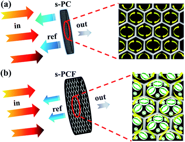
Based on the above results, the absorption-dominant shielding feature can be mainly attributed to the synergistic action of the perfect segregated CNTs networks and the cellular structure in the PSU domains. Fig. 7 illustrates the microwave disseminating across the solid and foamed segregated PSU/CNTs composites. After incorporating the uniform micropores in the CNTs conductive networks, EM reflections at the boundaries occurs, which is caused by the reduced impedance mismatch between the continuous composite wall and air. Compared with the solid composites, EM waves will easily enter into the interior of foams accompanying with a small amount of reflection on their surfaces. Moreover, once EM waves enter into the porous PSU matrix embedded with CNTs conductive networks, they will be scattered or multi-absorbed through dissipation in the form of heat. Therefore, introducing the microcellular structure into the segregated composites can provide the superior EMI shielding absorption property than these conventional materials.
Fig. 8 displays the compression properties of s-PCF-5 at three different densities (their cell morphology and cell size distribution are shown in Fig. 4, S4 and S5†). As shown in Fig. 8a, s-PCF shows the compressive behavior of an initial linear elastic region and a followed yielding region. Furthermore, it is obvious that the composite foams present a declining trend in both compression strength and compression modulus due to the increased foaming ratio. The results of compression tests indicate that smaller cell size will always induce the better mechanical performance, for example, upon the compressive strain of 30%, the mean pore size of s-PCF decreasing from 23.2 to 9.4 μm leads to 190.9% and 100.4% enhancement in the compression stress and compression modulus, respectively. In addition, the specific compression stress of s-PCF-5, defined by the ratio of compression stress and foam density also declined to 22.1 MPa cm3 g−1 as the foam density decreasing to 0.48 g cm−3, which further confirmed the negative effect of excessive foaming on mechanical property.
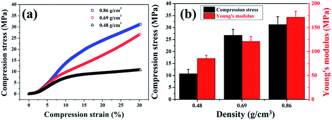 | ||
| Fig. 8 Compression performance of the composite foams: (a) compression-strain curves and (b) compression stress, Young's modulus of the s-PCF-5 with different density. | ||
4. Conclusion
In summary, we successfully fabricated PSU/CNTs composite foams with segregated conductive networks via integrating the solid-phase milling and scCO2 foaming. The formation of a porous segregated structure based on CNTs conductive layers selectively enriching on the interfaces of the porous polymer matrix significantly improve the utilization efficiency of CNTs. The obtained PSU/CNTs composite foams were provided with high conductivity (5.2 S m−1) and EMI SE (23.7 dB) at low CNTs concentration of 5.0 wt%, along with an extremely low percolation threshold of 0.06 vol%. Beneficially, the porous PSU/CNTs composites possessed an absorption-dominant shielding mechanism and markedly reduced EM reflection to the environment, compared to the compact ones with CNTs randomly distributed regardless inside or at the interface. Moreover, thanks to the inherent properties of the PSU matrix resin, even if the foam density drops to 0.69 g cm−3, the material still possesses strong mechanical properties. This study presents a facile, green method to manufacture the microcellular composites embedded with conductive CNTs networks and provides a new insight into the development of microcellular conductive materials. Therefore, it can be concluded that the prepared composite foams with excellent EMI shielding property and high strength may have great potential in aerospace and military applications.Author contributions
Yeping Xie, Wenhua Chen and Pengju Liu wrote the main manuscript text and prepared all figures and tables; Yeping Xie and Fan Ye designed and carried out the experiments; Wenhua Chen, Fan Ye and Jiahong Tang discussed the related results; Pengju Liu obtained the funding; all authors reviewed the manuscript.Conflicts of interest
The authors declare no competing interest.Acknowledgements
This work was supported by National Natural Science Foundation of China (51720105012, 51873131), Major Science and Technology Projects in Sichuan Province (2019ZDZX0018), and the Fundamental Research Funds for the Central Universities.References
- O. Erogul, E. Oztas, I. Yildirim, T. Kir, E. Aydur, G. Komesli, H. C. Irkilata, M. K. Irmak and A. F. Peker, Arch. Med. Res., 2006, 37, 840–843 CrossRef PubMed.
- S. Engels, N. L. Schneider, N. Lefeldt, C. M. Hein, M. Zapka, A. Michalik, D. Elbers, A. Kittel, P. J. Hore and H. Mouritsen, Nature, 2014, 509, 353–356 CrossRef CAS PubMed.
- Y. Zhang, Y. Huang, T. Zhang, H. Chang, P. Xiao, H. Chen, Z. Huang and Y. Chen, Adv. Mater., 2015, 27, 2049–2053 CrossRef CAS PubMed.
- J. Liu, H. B. Zhang, R. Sun, Y. Liu, Z. Liu, A. Zhou and Z. Z. Yu, Adv. Mater., 2017, 29, 1702367 CrossRef PubMed.
- D. X. Yan, P. G. Ren, H. Pang, Q. Fu, M. B. Yang and Z. M. Li, J. Mater. Chem., 2012, 22, 18772–18774 RSC.
- N. Yousefi, X. Sun, X. Lin, X. Shen, J. Jia, B. Zhang, B. Tang, M. Chan and J. K. Kim, Adv. Mater., 2015, 26, 5480–5487 CrossRef PubMed.
- H. Deng, L. Lin, M. Ji, S. Zhang, M. Yang and Q. Fu, Prog. Polym. Sci., 2014, 39, 627–655 CrossRef CAS.
- J. M. Thomassin, C. Jérôme, T. Pardoen, C. Bailly, I. Huynen and C. Detrembleur, Mater. Sci. Eng., R, 2013, 74, 211–232 CrossRef.
- S. H. Lee, S. Yu, F. Shahzad, W. N. Kim, C. Park, S. M. Hong and C. M. Koo, Nanoscale, 2017, 9, 13432–13440 RSC.
- G. Wang, G. Zhao, S. Wang, L. Zhang and C. B. Park, J. Mater. Chem. C, 2018, 6, 6847–6859 RSC.
- Y. Wu, Z. Wang, X. Liu, X. Shen, Q. Zheng, Q. Xue and J. K. Kim, ACS Appl. Mater. Interfaces, 2017, 9, 9059–9069 CrossRef CAS PubMed.
- Y. Xu, Y. Li, W. Hua, A. Zhang and J. Bao, ACS Appl. Mater. Interfaces, 2016, 8, 24131–24142 CrossRef CAS PubMed.
- Z. Zeng, H. Jin, M. Chen, W. Li, L. Zhou and Z. Zhang, Adv. Funct. Mater., 2016, 26, 303–310 CrossRef CAS.
- Z. L. Fang Ren, L. Xu, Z. Sun, P. Ren, D. Yan and Z. Li, Composites, Part B, 2018, 155, 405–413 CrossRef.
- J. X. Wancheng Yu, Z. Wang, Y. Huang, H. Yin, L. Xu, Y. Chen, D. Yan and Z. Li, Composites, Part A, 2018, 110, 237–245 CrossRef.
- W. P. Jie Li, Z. Fu, X. Tang, H. Wu, S. Guo and M. Wanga, Composites, Part B, 2019, 171, 204–213 CrossRef.
- G. B. Zunfeng Liu, Y. Huang, Y. Ma, F. Du, F. Li, T. Guo and Y. Chen, Carbon, 2007, 45, 821–827 CrossRef.
- T. A. Mohammad Arjmand, M. Okoniewski and U. Sundararaj, Carbon, 2012, 50, 5126–5134 CrossRef.
- S. T. Hsiao, C. C. Ma, W. H. Liao, Y. S. Wang, S. M. Li, Y. C. Huang, R. B. Yang and W. F. Liang, ACS Appl. Mater. Interfaces, 2014, 6, 10667–10678 CrossRef CAS PubMed.
- L. X. Huan Pang, D. Yan and Z. Li, Prog. Polym. Sci., 2014, 39, 1908–1933 CrossRef.
- L. L. Hua Deng, M. Ji, S. Zhang, M. Yang and Q. Fu, Prog. Polym. Sci., 2014, 39, 627–655 CrossRef.
- D. S. Fang Ren, Z. Li, L. Jia, Y. Zhao, D. Yan and P. Ren, J. Mater. Chem. C, 2018, 6, 1476–1486 RSC.
- H. P. Dingxiang Yan, B. Li, R. Vajtai, L. Xu, P. Ren, J. Wang and Z. Li, Adv. Funct. Mater., 2015, 25, 559–566 CrossRef.
- Y. L. Lichuan Jia and D. Yan, Carbon, 2017, 121, 267–273 CrossRef.
- L.-C. Jia, D.-X. Yan, C.-H. Cui, X. Jiang, X. Ji and Z.-M. Li, J. Mater. Chem. C, 2015, 3, 9369–9378 RSC.
- Y.-F. Liu, L.-M. Feng, Y.-F. Chen, Y.-D. Shi, X.-D. Chen and M. Wang, Compos. Sci. Technol., 2018, 159, 152–161 CrossRef CAS.
- F. Sharif, M. Arjmand, A. A. Moud, U. Sundararaj and E. P. L. Roberts, ACS Appl. Mater. Interfaces, 2017, 9, 14171–14179 CrossRef CAS PubMed.
- R. Sun, H.-B. Zhang, J. Liu, X. Xie, R. Yang, Y. Li, S. Hong and Z.-Z. Yu, Adv. Funct. Mater., 2017, 27, 1702807 CrossRef.
- D. Y. Lichuan Jia, X. Jiang, H. Pang, J. Gao, P. Ren and Z. Li, Ind. Eng. Chem. Res., 2018, 57, 11929–11938 CrossRef.
- Y. X. Hongji Duan, D. Yan, Y. Yang, G. Zhao and Y. Liu, Mater. Lett., 2017, 209, 353–356 CrossRef.
- L. J. Xiaopeng Zhang, G. Zhang, D. Yan and Z. Li, J. Mater. Chem. C, 2018, 6, 10760–10766 RSC.
- M. H. Al Saleh and U. Sundararaj, Carbon, 2009, 47, 1738–1746 CrossRef CAS.
- Y. H. Ning Li, F. Du, X. He, X. Lin, H. Gao, Y. Ma, F. Li, Y. Chen and P. C. Eklund, Nano Lett., 2006, 6, 1141–1145 CrossRef.
- Y. Y. Yadong Xu, D. Yan, H. Duan, G. Zhao and Y. Liu, Mater. Lett., 2018, 10, 19143–19152 Search PubMed.
- Y. Zhan, M. Oliviero, J. Wang, A. Sorrentino, G. G. Buonocore, L. Sorrentino, M. Lavorgna, H. Xia and S. Iannace, Nanoscale, 2019, 11, 1011–1020 RSC.
- J. Ling, W. Zhai, W. Feng, B. Shen, J. Zhang and W. G. Zheng, ACS Appl. Mater. Interfaces, 2013, 5, 2677–2684 CrossRef CAS PubMed.
- A. B. Martínez, V. Realinho, M. Antunes, M. L. Maspoch and J. I. Velasco, Ind. Eng. Chem. Res., 2011, 50, 5239–5247 CrossRef.
- L. Sorrentino, M. Aurilia, L. Cafiero and S. Iannace, J. Appl. Polym. Sci., 2011, 122, 3701–3710 CrossRef CAS.
- P. C. C. Forest, P. Cassagnau, B. Swoboda and P. Sonntag, Prog. Polym. Sci., 2015, 41, 122–145 CrossRef.
- M. C. b. Weili Song, L. Fan, M. Lu, Y. Li, C. Wang and H. Ju, Carbon, 2014, 77, 130–142 CrossRef.
- Y. P. Tong Liu, M. Zhu and S. Kobayashi, Nanoscale, 2014, 6, 2447–2454 RSC.
- Z. Li, Y. Jia and S. Bai, RSC Adv., 2018, 8, 2880–2886 RSC.
- T. K. Gupta, B. P. Singh, S. R. Dhakate, V. N. Singh and R. B. Mathur, J. Mater. Chem. A, 2013, 1, 9138 RSC.
- L. J. Hongyuan Wu, D. Yan, J.-f. Gao, X. Zhang, P. Ren and Z. Li, Compos. Sci. Technol., 2018, 156, 87–94 CrossRef.
- D. Feng, P. Liu and Q. Wang, Composites, Part A, 2019, 124, 105463 CrossRef CAS.
- M. Zhao, X. Ding, J. Mi, H. Zhou and X. Wang, Polym. Degrad. Stab., 2017, 146, 277–286 CrossRef CAS.
- D. Wu, Q. Lv, S. Feng, J. Chen, Y. Chen, Y. Qiu and X. Yao, Carbon, 2015, 95, 380–387 CrossRef CAS.
- I. Jurewicz, P. Worajittiphon, A. A. King, P. J. Sellin, J. L. Keddie and A. B. Dalton, J. Phys. Chem. B, 2011, 115, 6395–6400 CrossRef CAS PubMed.
- X. Fan, G. Zhang, Q. Gao, J. Li, Z. Shang, H. Zhang, Y. Zhang, X. Shi and J. Qin, Chem. Eng. J., 2019, 372, 191–202 CrossRef CAS.
- X. Fan, G. Zhang, J. Li, Z. Shang, H. Zhang, Q. Gao, J. Qin and X. Shi, Composites, Part A, 2019, 121, 64–73 CrossRef CAS.
Footnote |
| † Electronic supplementary information (ESI) available. See DOI: 10.1039/d0ra00942c |
| This journal is © The Royal Society of Chemistry 2020 |

