
 Open Access Article
 This Open Access Article is licensed under a Creative Commons Attribution-Non Commercial 3.0 Unported Licence
There's no place like real-space: elucidating size-dependent atomic structure of nanomaterials using pair distribution function analysis
Troels Lindahl
Christiansen†
 ,
Susan R.
Cooper†
and
Kirsten M. Ø.
Jensen
*
,
Susan R.
Cooper†
and
Kirsten M. Ø.
Jensen
*
Department of Chemistry and Nanoscience Center, University of Copenhagen, 2100 Copenhagen Ø, Denmark. E-mail: kirsten@chem.ku.dk
First published on 6th May 2020
Abstract
The development of new functional materials builds on an understanding of the intricate relationship between material structure and properties, and structural characterization is a crucial part of materials chemistry. However, elucidating the atomic structure of nanomaterials remains a challenge using conventional diffraction techniques due to the lack of long-range atomic order. Over the past decade, Pair Distribution Function (PDF) analysis of X-ray or neutron total scattering data has become a mature and well-established method capable of giving insight into the atomic structure in nanomaterials. Here, we review the use of PDF analysis and modelling in characterization of a range of different nanomaterials that exhibit unique atomic structure compared to the corresponding bulk materials. A brief introduction to PDF analysis and modelling is given, followed by examples of how essential structural information can be extracted from PDFs using both model-free and advanced modelling methods. We put an emphasis on how the intuitive nature of the PDF can be used for understanding important structural motifs, and on the diversity of applications of PDF analysis to nanostructure problems.
 Troels Lindahl Christiansen | Troels Lindahl Christiansen obtained his Ph.D. degree in Chemistry in 2019 from the University of Copenhagen, working in the nanostructure group under supervision of Kirsten M.Ø. Jensen. He is currently a postdoctoral researcher in the same group. His research focuses on structural characterization of metal oxide materials, as well as on developing new methods for pair distribution function analysis. |
 Susan R. Cooper | Susan R. Cooper received her Ph.D. in Chemistry from the University of Oregon in 2018 (with James E. Hutchison and Darren W. Johnson). She was supported by the National Science Foundation Graduate Research Fellowship program, and her research focused on the synthesis and structural characterization of iron oxide nanocrystals. She is now a Postdoctoral Fellow at the University of Copenhagen, funded by a Marie Sklodwska-Curie Individual Fellowship. Her research is focused on determining the nanoscale structural changes of small nanocrystals using total X-ray scattering and pair distribution function analysis. |
 Kirsten M. Ø. Jensen | Kirsten M. Ø. Jensen is an associate professor at Department of Chemistry at University of Copenhagen. She received her Ph.D. in Chemistry from Aarhus University in 2013. Following a postdoc position at Columbia University, she started her research group in Copenhagen in 2015. The research in her group concerns nanomaterials, focusing especially on the use of X-ray and neutron scattering to elucidate the structure and formation mechanisms of nanoparticles. Pair distribution function analysis is central to her research, and her group is active in development of new PDF modelling methods and experiments. |
Introduction
When looking back on the developments in materials chemistry over the past decades, it is clear that the discovery and advancement of new functional materials for advanced applications in e.g. energy technologies and many other fields has paralleled the ability of scientists to characterize atomic structure in materials.1,2 The very core of materials chemistry is understanding the relation between atomic structure and properties, and developments in materials chemistry heavily relies on structural knowledge. The ability to determine the atomic structure of materials began with the work of Max Von Laue and W. H. and W. L. Bragg in the 1910s.3–5 Epochal developments such as Rietveld refinement6 and the advent of large scale synchrotron and neutron facilities have allowed materials scientists to tackle structures, materials and problems of ever increasing complexity.7,8 The result is an explosion in the diversity of the materials we use every day, which has caused a fundamental change in our society and way of life.9 Still ahead lies challenges to develop cheaper, more sustainable and greener materials with improved properties, tailormade for new technologies. Nanomaterials have the potential to be part of this development and have contributed solutions in a number of important fields.10,11The size-dependent properties observed in many nanomaterials arise from effects including enhanced surface/volume ratio, and for the smallest nanoparticles, quantum confinement effects.12–14 In addition, the atomic arrangement in a material may also change upon nanosizing, which will dramatically influence the material properties. For example, a change of atomic structure is seen in metallic nanoparticles when going below 2–3 nm, leading to completely new properties.15–18 Despite this, the atomic structure of most nanomaterials is often assumed to be simple cut-outs of the structure of the corresponding bulk materials. This lack of understanding of an important nanoscale effect is most likely due to the difficulty in characterizing atomic structure in nanoscale materials.19 While the small domain size of the nanomaterials is the origin of emerging properties,12 it also poses a problem as it challenges the conventional crystallographic methods used for determining and refining the atomic structure of materials.19,20 In traditional powder X-ray diffraction (PXRD), the Bragg peaks that arise from atomic periodicity in crystalline materials are analyzed to obtain information on the atomic structure of the sample, however this is not sufficient for nanostructured materials, where the crystalline domain size is small and where the structure is often disordered. Consider the standard Rietveld refinement approach:6 Structural information is extracted by minimizing the difference between experimental PXRD data and Bragg peak intensities and positions calculated from a crystal structure model. Any deviation from perfect crystallinity is included by modelling the Bragg peak shape, which can yield microstructural information such as crystallite size and strain.21 However, any diffuse scattering arising from disorder in the material is normally considered background scattering and conventional Rietveld refinement is often inadequate for structural analysis of nanomaterials whose atomic structure is far from that of bulk, crystalline materials.22
Because of the challenges in applying traditional diffraction methods to nanostructured materials, many other techniques have been applied in the quest to characterize their atomic structure.23 For example, Extended X-ray Absorption Spectroscopy (EXAFS) can be used to characterize the local atomic structure in any material no matter its degree of atomic order, including disordered nanostructured materials.24 However, the structural information that can be obtained from EXAFS is limited to the first few coordination shells around an atom, making it difficult to fully characterize material structure.19 Transmission electron microscopy (TEM) is another widely used technique for nanomaterials, and with sufficient resolution, TEM can be applied in the characterization of the atomic structure of nanoparticles.25–27 However, highly disordered materials can be difficult to characterize from microscopy methods alone and a limited number of particles can be analyzed at a time. Since the turn of the century, X-ray Total Scattering (TS) and Pair Distribution Function (PDF) analysis has been proven to be an extremely powerful technique for the characterization of material structure and has evolved from a method mainly used for characterization of liquids and amorphous matter into a powerful tool for elucidating the atomic structure of solid state materials.20,28,29 In the early days of PDF analysis of materials, in the late 1990s and early 2000s, the method was an exotic technique applied mainly by solid state physicists to study the local structure in bulk, crystalline materials exhibiting e.g. superconductivity or ferroelectricity.30,31 PDF is still widely used for this type of materials, but since then, the diversity of the applications of PDF has grown tremendously, and PDF is now an important method for structure characterization in chemistry,32 energy materials,33–37 geology,38–40 pharmaceuticals,41–43 and other fields.
A PDF is a Fourier transform of total scattering data and, as described further below, represents the distribution of all interatomic distances in a material.22 When treating total scattering data, one does not discriminate between diffuse scattering and Bragg scattering, and the PDF thus includes information on the atomic structure of any kind of material; crystalline, nanostructured, disordered, or fully amorphous.28 A barrier to wide adoption of the use of PDF in the past was the challenges in measuring high quality scattering data to high momentum transfers, Q, which is needed to obtain high resolution in real-space.22 Now, the increase in X-ray flux and X-ray energy available at synchrotron sources have made the development of dedicated PDF beamlines possible.20,22 Combined with developments in experimental methods, such as the rapid-acquisition PDF (RA-PDF) method,44 and user-friendly software,45–49 PDF has become a widely accessible technique for a large community of scientists.31
PDF analysis can now be considered a mature technique capable of characterizing a range of different nanostructures, and its use in several fields has been reviewed in the past.33,50–54 With this review, we focus on the application of PDF in studies of the size-dependent atomic structure in nanomaterials and aim to give an overview of some of the different approaches that have been applied in studies of nanosize-induced structural changes. We will review examples of PDF studies that use a variety of strategies for data analysis. The PDF method and PDF theory has already been thoroughly reviewed and described in papers and textbooks,22,55,56 and we therefore only give a short description of the anatomy of a PDF to aid in understanding how structural information can be extracted from total scattering data and PDF analysis before reviewing examples of its use.
Obtaining and reading a PDF
A PDF is obtained by Fourier transforming total scattering data. The Fourier transform is done over the structure function S(Q), which represents the normalized, coherently scattered intensity from the sample, as here expressed for X-rays:22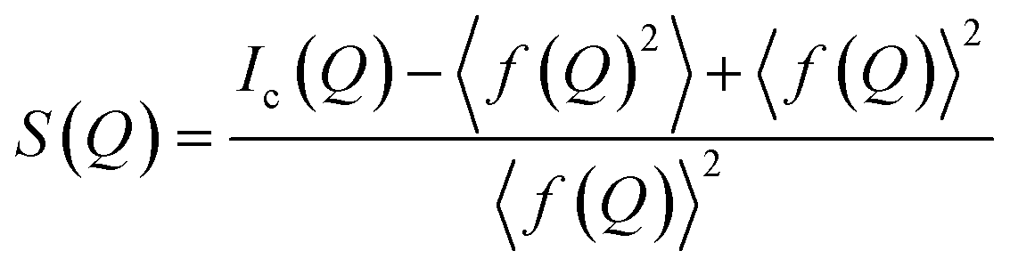 | (1) |
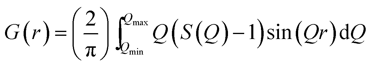 | (2) |
 used in the Fourier transform determines the amount of information and detail that can be extracted from the PDF, and generally, a Qmax value of at least 15–20 Å−1 is needed to extract atomic scale structural information, although this value is highly dependent on the purpose and aim of the study. The need for large Q-ranges means that high energy X-rays or neutrons with a short wavelength should be applied. High flux is furthermore required, as good statistics in the S(Q) function even at the highest Q-values are needed in order to minimize noise in the PDF. In the case of X-rays, total scattering studies are therefore often done at high energy synchrotron sources with dedicated PDF beamlines.28 However, PDF analysis is also possible with laboratory instruments using e.g. Ag or Mo X-ray tubes.59 Total scattering measurements can also be performed using neutrons57 or electrons.60 We focus here on X-rays which is most widely used for nanostructure analysis, but the choice of radiation depends entirely on the sample and scientific aim in question.
A PDF represents the distribution of all interatomic atomic distances present in the structure of a sample. Due to the intuitive nature of the PDF, significant structural insight is available in the PDF from model-free analyses. We show this for a series of very simple, discrete and isolated structures in Fig. 1. In Fig. 1A, a simulated PDF for a hypothetical, one-dimensional structure consisting of a chain of 21 atoms with a bond distance of 3 Å is shown. The first peak in the PDF, at 3 Å, is at the distance between two adjacent atoms; the second peak in the PDF at 6 Å is at the distance between the next pair of atoms, and all subsequent peaks in the PDF follow this same pattern. If the distance between the atoms increases, the peak positions will change as is shown in the insert in Fig. 1A, where the interatomic distance was changed in the simulations to 3.6 Å. The PDF peak width is determined by the distribution of atomic distances for an atom–atom pair. Fig. 1B demonstrates this effect on the PDF in terms of increased thermal vibrations, which increases the PDF peak width. The size of the structure in question also affects the PDF. In Fig. 1C, we show this effect in the G(r) by comparing the PDF simulated from a chain of 6 atoms with that simulated from the chain of 21 equidistant atoms. Lower intensity is observed in the PDF peaks originating from the 6 atom chain compared to the 21 atom chain as fewer atomic pairs are present in the short chain. Furthermore, the intensity of the PDF peaks from the shorter chain diminish quicker with r, and there are no PDF peaks at r values larger than the size of the structure. In studies of nanoparticles, this effect can be used to characterize the size of crystalline domains or crystallite sizes. The PDF peak intensity is proportional to the number of occurrences of an atomic pair; however, the peak intensity is also influenced by the scattering power of the atoms in the pair. Fig. 1D shows a hypothetical structure consisting of two different atoms, Au (gold) and Na (purple). Na (Z = 11) has much lower scattering power than Au (Z = 79), and peaks originating from atomic pairs involving Na (i.e. Na–Na and Na–Au) will therefore have a lower intensity than Au–Au peaks.
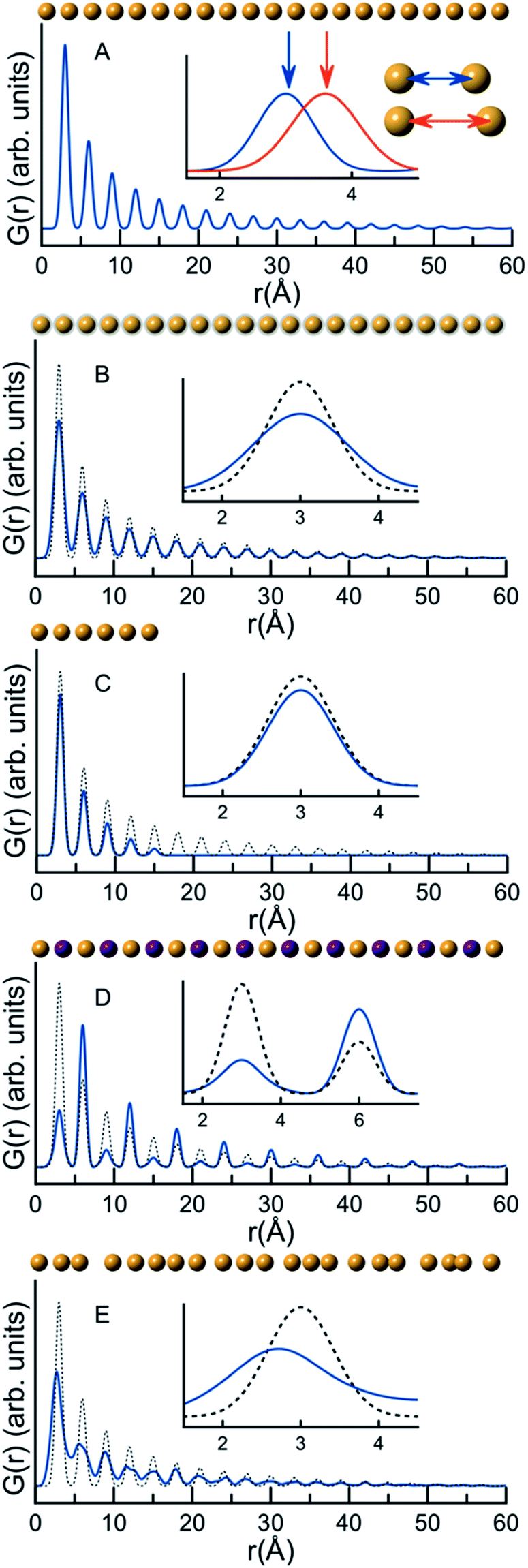 | ||
| Fig. 1 G(r) functions calculated for hypothetical 1D atomic structures. A–E illustrate different aspects of the PDF and how they are interpreted in relation to atomic structure: (A) the impact of atomic coordinates on peak position, (B) the impact of atomic vibration on peak broadening, (C) the impact of crystallite size on the extent of the PDF, (D) the impact of atomic identity (as seen when replacing Au with Na, an element with lower scattering power) on the peak intensity and (E) the effects of disorder on the PDF. The blue line is the simulated PDF under consideration, while the dotted line is the PDF simulated in A. | ||
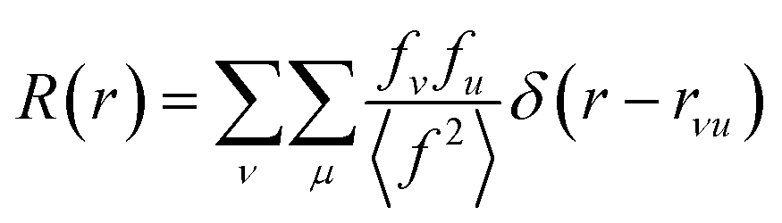
The properties of PDFs described above are summarized in eqn (3) and (4), which shows how the PDF can be calculated from a structural model. The Radial Distribution Function (RDF), or R(r) is calculated as the sum of delta functions representing all interatomic distances in the sample, where their weight is given from their (X-ray) scattering power of the atoms in the pair:
 | (3) |
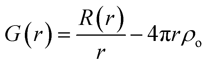
A pair of atoms consisting of atoms v and u will give rise to a delta function at rvu, which is the distance between the two atoms. The peak intensity will be given from the scattering power of the two atoms through their form factors f. By summing over all atomic pairs in the sample, the full R(r) is obtained. The R(r) is a member of a large family of pair distribution functions, which all express the same information in slightly different ways as discussed in detail by Keen.61 The reduced pair distribution function, G(r) illustrated in Fig. 1, is easily obtained from the R(r):
 | (4) |
The PDFs illustrated in Fig. 1A–D and discussed above originate from very simple, well-ordered and hypothetical systems. In Fig. 1E, we have tried to simulate effects of disorder in a hypothetical atomic structure by multiplying all atomic positions in the 21 atom 1D chain by a random number. Atomic disorder can influence any and all of the aspects of the PDF discussed above, and thus the PDF peaks in Fig. 1E appear both broadened and shifted due to the disorder. Because all of these simultaneous and inseparable changes affect the features of the PDF, structural disorder is significantly more challenging to model and characterize as will be clear throughout this review when discussing PDFs from real nanomaterials.
Modelling of PDFs
As seen from Fig. 1 and as illustrated in examples below, much structural insight can be obtained from model-free PDF analysis. However, often, modelling of PDFs allow a greater amount and more reliable information to be extracted. Given an atomic structure model, the corresponding PDF can easily be calculated either from a crystal structure or from discrete structural objects such as molecule-like clusters or nanoparticles. The calculated PDFs can then be fitted to experimental data to obtain a refined model for the sample in question by varying the structural parameters.As we will see throughout the review, several strategies can be applied in modelling PDFs from nanoscale materials of varying complexity. A very widely used approach is the ‘real-space Rietveld’ method, implemented e.g. in the programs PDFgui,45 DiffPy-CMI62 and TOPAS.47 As the name implies, real-space Rietveld refinement is very similar to its namesake in reciprocal space. The structural model is built from a crystallographic unit cell assuming translation symmetry. Variables such as unit cell parameters, fractional atomic coordinates, isotropic or anisotropic atomic displacement parameters (ADPs), and site occupancies can be refined, and most often, the space group symmetry is preserved in the refinements. Effects of crystallite size are usually implemented through an envelope function that dampens the PDF signal as r increases. The envelope function corresponds to a particular particle shape which is usually assumed to be spherical, but can be introduced to reflect many shapes and size distributions.63,64 While this method is conceptually similar to Q-space Rietveld refinements, modelling the real-space PDF allows analysis of the structure in e.g. very small nanoparticles, where the peak broadening challenges conventional Rietveld refinements in Q-space. The local structure and disorder in materials can also be analyzed by e.g. fitting r-dependent models that include a separate description of the local structure and the average structure.65 As many of the examples in the review will show, the applications of real-space Rietveld analysis are incredibly diverse, and with structural insight and creative model construction, this method can be applied to tackle even complex nanostructure analyses.
The real-space Rietveld approach is mostly suited for materials where the atomic structure shows periodicity and is related to the crystal structure of the corresponding bulk material or other known crystalline structures. In many materials, containing e.g. molecular units, large ionic clusters, or metallic nanoclusters, this approach cannot be used to describe the atomic structure. PDF modelling can then be done without assuming translation symmetry and periodicity, i.e. by building up a discrete structural object through its atomic coordinates. This method, used for small nanoparticles, clusters and molecules, takes advantage of the Debye equation66 for calculation of a scattering pattern and subsequently the PDF.67 In the case of nanoparticles, an entire structural model can be built and fitted to the data. Software packages such as DISCUS68 and Diffpy-CMI62 facilitate modelling of PDFs of discrete structures. Analysis of scattering patterns using the Debye scattering equation can also be done directly in Q-space, i.e. without Fourier transforming the data,69 for example using the Debussy program.70 Unlike in Q-space or real-space Rietveld analysis, where the space group symmetry can be applied to constrain the parameters in the refinements, extra care has to be taken in limiting the number of refinable parameters when fitting discrete models. However, as examples below will show, this approach can be extremely powerful for structural analysis of small nanoparticles.
PDF analysis can also be done using ‘large-box modelling’, e.g. through the use of Reverse Monte Carlo (RMC) methods, where thousands of atoms in a structure are allowed to move to better fit experimental PDFs.71–73 While widely applied for fully amorphous and disordered crystalline materials, this approach has been less used for nanomaterials, although recent examples have shown its application to nanoparticles.74–76
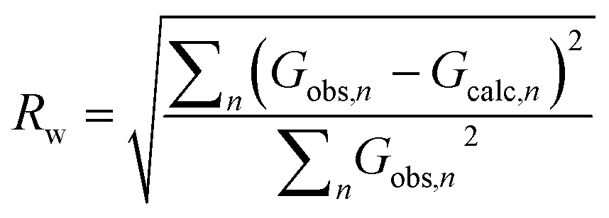
Independent of the approach to modelling, the quality of a fit to a PDF is often analyzed through the Rw-factor, which is a measure of the difference between the calculated (Gcalc) and experimental PDF (Gobs) that is calculated as:22
 | (5) |
It is difficult to establish exactly what the Rw value for a ‘good’ fit should be. PDF is often used to characterize very different materials with varying degrees of structural order, and the Rw-value that can be expected depends greatly on the structure type investigated as well as the data quality. When fitting high quality PDFs from highly ordered, crystalline models, very good agreement between data and model can often be obtained with Rw values between 1–5%. This is rarely the case for nanostructured and disordered materials, where satisfactory fits are reported with Rw values above 15%. Often, the complexity of a disordered nanomaterial is too high for a relatively simple model to fully describe e.g. heterogeneous size and structure. The quest for a good fit is always a compromise between extending the number of parameters in the model (which may result in over-fitting and unphysical models) and the development of simple models that describe important structural features in the sample. A visual inspection of the fit is key when evaluating the fit quality, as large features in the difference curve are clear indications of an inadequate structure model. Due to the intuitive nature of a PDF, features in the difference curve can often be directly linked to a structure motif, which can aid in developing better models, as discussed further below.
Nanostructure from PDF analysis
In the following, we will review examples of the use of PDF for analysis of atomic structure in nanomaterials. This is a large and quickly developing field, spanning over a range of material types, applications, experimental methods and approaches to structure analysis. We do not aim to cover the whole field, but we have chosen examples applying different analysis methods to the structures that appear on the nanoscale; from model-free analysis, to real-space Rietveld refinements, and discrete cluster modelling of varying complexity. The examples range from early applications of PDF for nanoparticle studies to recent examples of its use. As will be seen from the diverse examples, the method to be used for a specific study is highly dependent on the problem that is under investigation, and what information is sought. This means that PDF analysis of the atomic structure in nanomaterials requires a great deal of creativity, structural understanding and chemical intuition. We have divided the examples into three material classes; metal chalcogenides, metallic nanoparticles and oxides, and in this way, we try to cover a broad range of materials as well as approaches for PDF analysis.Size-dependent structure of metal chalcogenide nanoparticles from PDF analysis
 | ||
| Fig. 2 Illustration of the stacking sequence in the wurtzite structure (A) and the zinc-blende structure (B). Cations are represented as purple dots, and anions are represented as green dots. The tetrahedrally coordinated Cd cations are shown to emphasize the layering of the structure. | ||
In small particles of CdSe it has been difficult to distinguish between the zinc-blende and wurtzite phases using conventional diffraction and microscopy techniques.87,88 Using PDF, Masadeh et al.86 fitted structural models (using the real-space Rietveld approach) of both phases to the PDF of bulk CdSe and nanoparticles with approximate sizes of 3.5 nm (III), ca. 2.9 nm (II) and 2.0 nm (I). The fits revealed unphysically large ADPs that increase with decreasing particle size. In the wurtzite fit, anisotropic ADPs were applied, and they showed increased values along the stacking direction in the unit cell i.e. along the z-axis. The increased ADPs in the stacking direction were interpreted to indicate the presence of stacking faults, and the increase in ADPs with decreasing particle size could therefore be interpreted as an increase in stacking fault density. To test this hypotheses, the authors built CdSe nanoparticle models with different stacking fault densities using the DISCUS68 program, and PDFs of the different structures were simulated applying fixed, isotropic ADP values. The simulated PDFs were subsequently fit using a wurtzite model with anisotropic ADPs, i.e. using the same approach as for the experimental data. Again, the refined ADPs from the simulated data were unphysically large in the stacking direction due to the stacking faults introduced in the models. However, the refined ADP values along the stacking direction could now be directly correlated to the specific stacking fault density introduced in the constructed models. Using this information, the stacking fault density in the samples were determined to be ca. 35% in bulk CdSe and 50% in the nanoparticles. The experimental PDFs were then fit with structural models with the appropriate stacking fault density, which yielded excellent fits with physically reasonable ADP values.
In a later paper, Yang et al.89 applied the real-space Rietveld approach to extract approximate stacking densities in similar CdSe nanoparticles, using two-phase models. In Fig. 3, real-space Rietveld refinements of a CdSe nanoparticle PDF are shown using a zinc-blende model (top), a wurtzite model (middle) or a two-phase model using both structures (bottom). Only the two-phase model is able to correctly describe all positions and the intensity of the PDF peaks. The authors recognized that the PDFs of wurtzite and zinc-blende would be identical for the first two stacking layers (AB) but would differ in the third layer (A or C). They defined a stacking fault density with regards to wurtzite as P(C), which is the probability of a C-layer occurring in third position of the stacking sequence. Thus, for wurtzite P(C) = 0 (no C in third layer), while P(C) = 1 (C always in third layer) corresponds to the zinc-blende structure. A wurtzite structure with stacking faults would have a P(C) between 0 and 1. In the study, P(C) was approximated by refining the phase fraction between wurtzite and zinc-blende in a limited r-range of the PDF that only includes the first three layers (1–10 Å). The mixed phase models showed an excellent agreement with the data of the nanoparticles, except for the PDF from ultra-small CdSe particles (ca. 1.3 nm), which appear to have a different atomic structure to the other particles that was not elucidated from the broad and dampened PDF peaks. Consistent with the previous study, the stacking fault density is seen to increase with decreasing particle size from ca. 8% in the bulk sample to ca. 30% in the small nanoparticles. The correct stacking sequence after the third layer of stacking is not described in a two-phase real-space Rietveld model, however, the advantage of this approach is the ease and computational speed by which it can be applied to extract stacking fault densities.
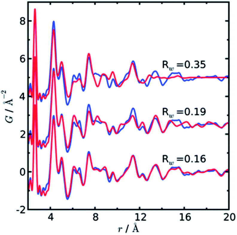 | ||
| Fig. 3 Three real-space Rietveld refinements of a PDF from CdSe nanoparticles (3.5 nm). The PDF is fit using a zinc-blende model (top), a wurtzite model (middle) or a two-phase model using both structures (bottom). The blue line is experimental data and the red line is a simulated PDF. Reproduced from Yang et al., Phys. Chem. Chem. Phys., 2013, 15, 8480–8486 (ref. 89) with permission from the PCCP Owner Societies. | ||
Both papers on the structure of CdSe nanoparticles (Masadeh et al.86 and Yang et al.89) also demonstrate how model-free analysis can allow information to be extracted from PDF. By simply observing the changes in the width and position of the first Cd–Se peak in the PDFs, it is possible to extract information on the strain in the particles. Homogeneous strain will cause a shift in all bond-lengths, which causes the position of the peak in the PDF to move, while inhomogeneous strain causes broadening of the peak due to a non-uniform distribution of bond-lengths. The width and position can be extracted by fitting e.g. a Gaussian function to the peak, as seen in Fig. 4a. The resultant changes in position and width is shown as a function of particle size in Fig. 4b and c, respectively. From the figures it is evident that both the homogenous (position) and inhomogenous (width) strain increase rapidly with decreasing particle size, consistent with the increase in structural disorder and the presence of stacking faults evident from the modelling.
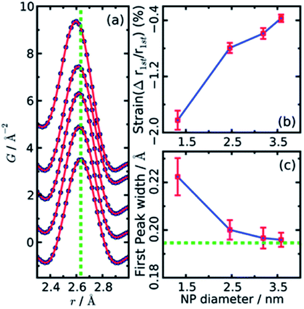 | ||
| Fig. 4 (a) Gaussian fits to the first peak in experimental PDFs of CdSe nanoparticles of various sizes. Data are represented as black dots, and the fit as a red line. The green dotted line indicates the peak r value from a bulk sample. (b) The relative percentage change in position as obtained from the Gaussian fits, plotted as function of nanoparticle size. (c) Changes in peak width obtained from the Gaussian fits, plotted as function of nanoparticle size. The green dotted line indicates the value of peak width from a bulk sample. Reproduced from Yang et al., Phys. Chem. Chem. Phys., 2013, 15, 8480–8486 (ref. 89) with permission from the PCCP Owner Societies. | ||
While the intuitive nature of PDF can facilitate the description of defects and stacking faults, it should be noted that stacking faults and other defects in metal chalcogenides are also often studied in Q-space analysis of total scattering data,90–92 or in a combination of Q- and r-space refinements.93,94 For example, Mosheni et al. used the Debye equation in a complex and highly advanced analysis of small and wide angle X-ray scattering data to determine stacking faults and faceting in CdSe nanoparticles.95 Niederdraenk et al. used ensemble modelling to determine distributions of stacking faults, sizes and morphologies of small CdSe, ZnS and ZnO nanoparticles.96,97
Other chalchogenide nanoparticles crystallize in the rock salt structure, where PDF and other scattering methods have been applied to study structural distortions from the ideal lattice in the bulk.98 Studies of nanoparticles using total scattering methods have revealed size-dependent structural distortions,99 and PDF and a suite of nanoscale characterization techniques have been applied to study nanoparticles in the PbmSb2nTem+3n system, where compositions that do not have stable bulk counterparts can be synthesized as nanomaterials.35
 | ||
| Fig. 5 (A) Experimental PDF of ZnS nanoparticles (black line) compared to a simulated PDF from a 3.4 nm ZnS particle with a zinc-blende structure (grey line) and a simulated PDF from bulk zinc-blende (dashed line). (B) Fit (grey line) to the experimental PDF of ZnS nanoparticles (black line), taking into account particle size and using atomic displacement parameters (MSRD) from a bulk ZnS sample. The r dependence of the additional mean square displacement parameter and the short-range order parameter included in the model is shown in the insert. Reproduced from Gilbert et al., Science, 2004, 305, 651–654.104 Reprinted with permission from AAAS. | ||
PDF analysis has also been used to determine the structural effects of changing the environment surrounding nanoparticles, e.g. the effect of ligands, solvent, or the atmosphere.103,105–107 For example, Zhang et al. studied the dependence of the atomic structure on hydration in 3 nm ZnS particles.108 The particles were synthesized in anhydrous methanol, and using PDF analysis, it was found that the as-synthesized nanoparticles were highly disordered as reflected by the less than 1 nm coherent scattering domain seen from the PDF. However, when water was added to the particles, a stabilization of the surface occurred, and the atomic structure of the particles became much more ordered. The PDF clearly showed an increase in the size of the coherently scattering domain as could be deduced from peaks at higher r-positions in the PDF. Here, disordered particle atomic models were constructed using molecular dynamics simulations by relaxing various sizes of ZnS particles with and without water on the surface. Models were found that fit well with the experimental PDFs and the simulations showed that the surface restructuring in the non-passivated particles penetrated approximately 0.8 nm, leaving only a very small crystalline particle core unperturbed.
Size-dependent structure in metallic nanoparticles
Metal nanoparticles have many important technological applications that often rely on properties unlocked at the nanoscale.109,110 For instance, gold is a noble metal in bulk form, but when reduced to the nanoscale it exhibits size-dependent tunable catalytic behavior.111 The existence of a size-dependent structural change from the fcc structure, seen in bulk metals, to a non-fcc structure within small metallic nanoparticles has long been known from studies using HR-TEM and PXRD,15,112–114 where the presence of e.g. decahedral and icosahedral structures were observed. Icosahedral and decahedral structures are shown in Fig. 6C and D, along with an fcc (A) and a tetrahedrally close packed (tcp) Frank–Casper phase (B)115,116 that will be discussed further below. The decahedral and icosahedral structures contain multiple twinned fcc regions that make up discrete particles that express different surfaces and internal atomic structure.117–119 PDF is a useful technique to characterize such structures120,121 and early studies helped to demonstrate the ability of PDF analysis to elucidate nanostructure before the technique was widely used in the materials chemistry communities.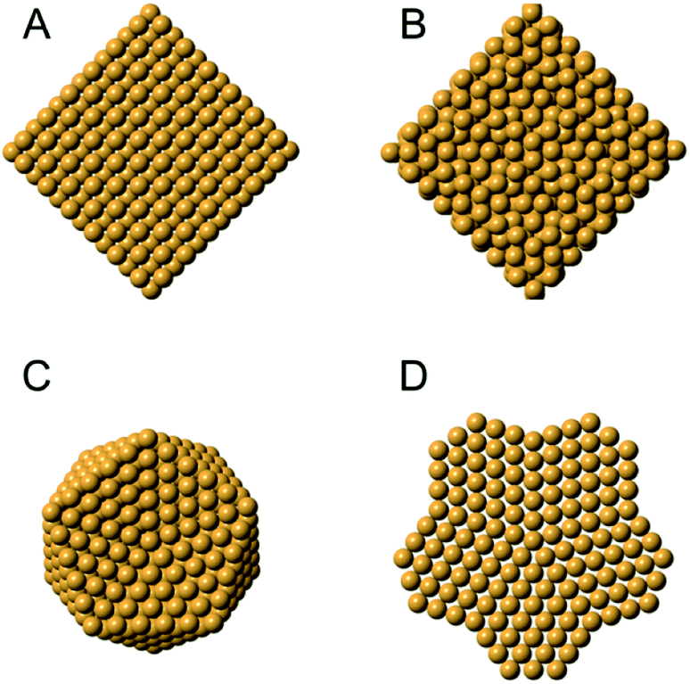 | ||
| Fig. 6 Different structures seen in metal nanoparticles. (A) The face-centered cubic (fcc) structure; (B) the tetrahedrally close-packed (tcp) Frank–Casper phase, (C) a 561-atom icosahedral cluster core, and (D) an 811-atom decahedral cluster core. The structures in C and D are generated using the ASE module.122. | ||
Since then, several PDF and total scattering studies have focused on the structures of non-fcc and hcp structures in metallic nanoparticles.117,123,124 Vargas et al. used PDF and TEM to characterize the atomic structure in long and ultrathin Au nanowires. In this study, many possible structural models in 2 nm by 12 nm nanowires were generated and energetically optimized using Molecular Dynamics simulations. The models tested included structural models that are adopted by bulk gold (fcc and hcp structures), models previously observed in gold nanowires (Boerdijk–Coxeter–Bernal helix, spirals and attached gold nanoparticles) and models from other bulk metals (α-Mn, β-Mn and β-W). For the models that most closely resembled the PDFs obtained from the synthesized nanowires, RMC refinements were performed. It was found that α-Mn, which closely resembles a tcp structure, provided the best fit to the data.76,125 The nanowires are formed from particle assembly in solution and it was suggested that they adapt the tcp-like structure in order to maintain close atomic packing while avoiding the strain introduced by the high surface area of the nanowires.
Recently, Banerjee et al.126 did a comprehensive study of a range of different metallic nanoparticles, including Pt, Pd, Au and alloys such as CoPd and PtRu. The study puts a large emphasis on scrutinizing the fit residual, and Fig. 7 shows the fit residual obtained when fitting a range of different metal nanoparticle PDFs with an fcc model using the real-space Rietveld approach. The residual from the fit of a bulk Ni standard with an fcc Ni model is seen at the bottom of the figure and is essentially a flat line with small fluctuations mostly due to noise in the data. In comparison, the fit residuals of all investigated nanoparticles show large distinct features. Features exhibited in the fit residual is an indication that the applied fcc model is insufficiently describing the structural information available in the PDF, and the authors proceed to show that a discrete decahedral nanoparticle model significantly reduces the fit residual in comparison with the fcc model. Nanoparticle models with similar particle shape, but without the presence of twin domains were compared to decahedral models, and generally resulted in poorer fits of the experimental PDFs. This shows that the PDFs reflect an actual rearrangement at the atomic level that can be described by twinned domains of an fcc structure rather than an effect of the morphology of the nanoparticles. The decahedrally twinned cluster cores were observed in a majority of nanoparticles used in the study, and the authors point out that including this nanostructure in models of metallic nanoparticles should take precedent over employing complex surface rearrangements or ligand interactions.
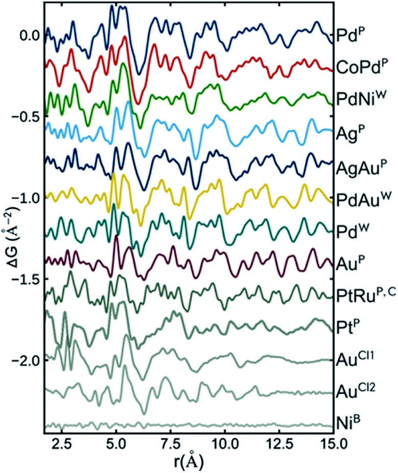 | ||
| Fig. 7 Fit residuals from real-space Rietveld refinements using an fcc model to several experimental PDFs of different metallic nanoparticles. The difference curve has been scaled for easier visual comparison. Reprinted with permission from Banerjee et al., J. Phys. Chem. C, 2018, 122, 29498–29506.126 Copyright 2018 American Chemical Society. | ||
In an innovative approach to structural characterization of metallic nanoparticles, Banerjee et al. have moved on to show that the identification of metallic cores can be done in an automated manner.127 The configurations of the different cluster cores such as icosahedral and decahedral structures are well-known, and software packages such as ASE122 can be applied to build nanoparticles of different sizes, shapes and geometries. The authors generated a large number of discrete nanoparticles, ranging in size from tens of atoms to around 1500 atoms with different geometries and subsequently fit all of them to an experimental PDF of Pd nanoparticles. Fig. 8 illustrates the fit quality (Rw) as a function of number of atoms for a range of different structure types. The Rw value obtained in a real-space Rietveld fit using an fcc structure is given as the green circle with the letters AC (attenuated crystal). The cluster-screening process reveals that several of the discrete nanoparticle models yield significantly lower Rw values when fit to the experimental PDF. Initially, fcc-based structures without twinning were tested, and the best model found from this initial cluster-screening is a cuboctahedron with 225 atoms. However, the difference curve in the insert of Fig. 8 reveals significant features similar to those shown in Fig. 7, and therefore, the cuboctahedron model is not fully describing the Pd nanoparticle structure, due to the lack of a twinned cluster core. When also considering twinned cluster cores such as icosahedral and decahedral models in the structure search the Rw value are further improved, and the best model found is a 609 atom decahedron. The decahedron is nearly twice as large as the cuboctahedron model found in the initial search. The decahedron nanoparticle model has a diameter of ca. 3.6 nm, which is much closer to the TEM estimate of 3.0 ± 0.3 nm than the cuboctahedron model. The reason for this is that the size initially extracted from the PDF reflects the size of the coherently diffracting twinned fcc unit in the structure, and not the physical size of the particles as seen in TEM. The size of the fcc unit in a 3.6 nm decahedron particle is approximately 2 nm, which explains the small size obtained when applying the non-twinned fcc models. This further demonstrates the importance of determining the correct cluster core when extracting structural information from PDF. In general, large discrepancies between the physical size (TEM, SAXS) and the size of the coherently scattering domain (PDF, PXRD) can be used as an indication of the presence of nanostructure which then must be included in a structural model, as is also discussed for the ZnS particles above.
 | ||
| Fig. 8 R w values obtained for a number of discrete non-twinned nanoparticle models, fitted to the experimental PDF of Pd nanoparticles. The Rw values are plotted as a function of the number of atoms in the structure. The teal circle labelled AC corresponds to the Rw obtained from a real-space Rietveld refinement of the data using an fcc model. Symbols for the discrete nanoparticle models with different geometries can be seen in the bottom right of the figure. Figure from Banerjee et al., Acta Crystallogr., Sect. A: Found. Adv., 2020, 76, 24–31.127 | ||
The novel method of algorithmically generating clusters and automatically screening them for their potential to fit experimental PDFs is promising, as it greatly increases the number of models that can be assessed, as well as reducing human selection bias in the model. If the results from the structure-screening are properly scrutinized, the method has the potential to greatly aid in the characterization of nanomaterials. For instance, we have recently applied a similar method to disordered MoOx nanostructures supported on alumina and zeolite particles. In this study, a large number of possible models were algorithmically generated and used to extract information on the average structural motifs from the best models discovered.128
An even more pronounced structural rearrangement from the common fcc structure has been observed for NiPd alloy nanoparticles in a study by Doan-Nguyen et al.129 Here, TEM was used to demonstrate a very high uniformity of particle size in the synthesized particles as shown in Fig. 9b. From the corresponding PDFs in Fig. 9a, it is readily apparent that significant changes in atomic structure occurs below 5 nm. The PDFs of the particles larger than 5 nm display distinct peaks that can be modelled reasonably well using an fcc model in the real-space Rietveld approach. However, for the 5 nm particles, the much broader PDF peaks signify a large degree of structural disorder. The PDF could not be modelled using the same fcc model, and in fact the signal in the experimental PDF is out-of-phase with the fcc model due to a very different distribution of atoms in the model and PDF. The PDFs could be modelled using an icosahedral core model with very high ADPs to encompass the large structural disorder, and the authors note that the PDF is very similar to that found from bulk-metallic glasses. The model used to fit the data for the <5 nm particle provides a reasonable fit of the PDF data; however, the interpretation of the model is somewhat difficult, and the authors also show that the PDF signal is close to a damped sinusoidal wave. This is a ubiquitous challenge in PDF studies of highly disordered materials.89,128,130,131 In the case of highly disordered materials, atomic structure cannot be determined with the same specificity presented previously. Instead, as is discussed in the PDF literature available on bulk metallic glasses132 or liquids,133 information about the degree of structural order/disorder and the possible local structural motifs can be elucidated.
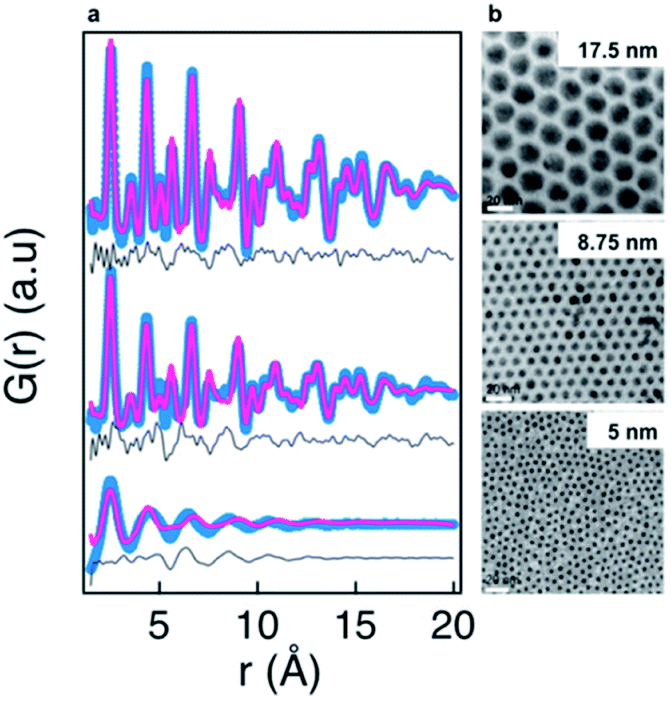 | ||
| Fig. 9 Characterization of three NiPd samples using PDF and TEM. (a) Fits of PDFs using an fcc structure. The experimental PDF is shown in blue, the calculated PDF in red, and difference curve in grey. (b) TEM images obtained for the three NiPd samples, scale bar is 20 nm. Reprinted with permission from Doan-Nguyen et al., ACS Nano, 2014, 8, 6163–6170.129 Copyright 2014 American Chemical Society. | ||
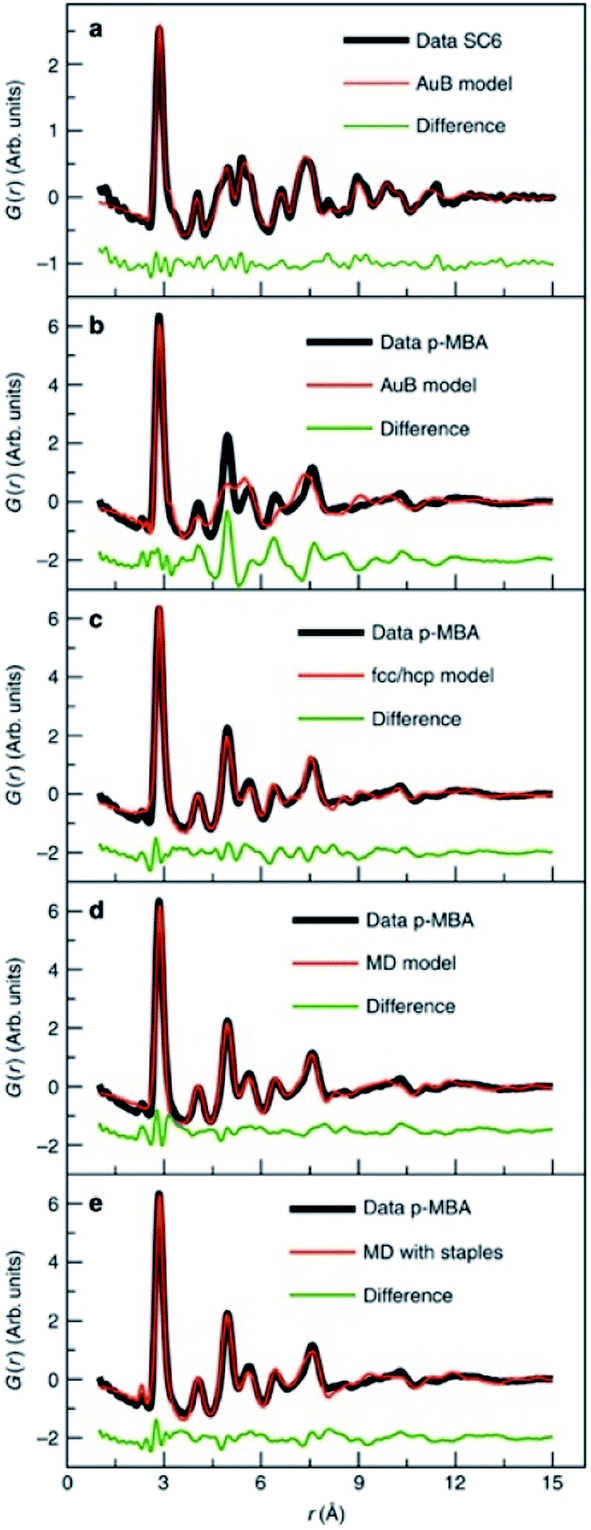 | ||
| Fig. 10 Fits to experimental PDFs from Au144(SR)60 samples. (a) Fit of an icosahedral structure model to data collected from Au144(SC)60. (b) Fit of an icosahedral structure model, (c) of an fcc/hcp model, (d) a 114 atom decahedral model and (e) a decahedral model with ‘staples’ to the PDF obtained from Au144(p-MBA)60. From Jensen et al., Nat. Commun., 2016, 7, 11859.140 | ||
Size-dependent structure in metal oxide nanoparticles
Metal oxides have a wide variety of applications including energy production and storage154,155 human health,156 and environmental remediation157 that rely on size-dependent properties.158 Synthetic control of size and structure has been harder to achieve in the synthesis of metal oxide nanoparticles compared to metallic or metal chalcogenide nanoparticles,159 and generally, the effects of nanosizing on atomic structure are less clear compared to e.g. the simple metallic structures as described above. A wealth of different metal oxide crystal structures exists that are commonly composed of tetrahedrally and octahedrally coordinated cations forming a range of canonical metal oxide structures that include e.g. the rutile, perovskite and spinel structures. The common structural units, trends in crystal chemistry and known defect motifs from bulk materials provide a valuable toolbox when characterizing size-dependent structures of metal oxide nanomaterials. | ||
| Fig. 11 Fits to PDFs from nanostructured molybdenum oxide using different structural models. (A) Fit of the data with a bulk rutile structure and (B) with an ‘interwoven’ rutile model. (C) High-resolution annular dark field TEM image obtained from the sample, overlaid with the rutile structure. The image shows intensity in the unoccupied sites in the rutile structure. Reprinted with permission from Lindahl Christiansen et al., ACS Nano, 2019, 13, 8725–8735.131 Copyright 2019 American Chemical Society. | ||
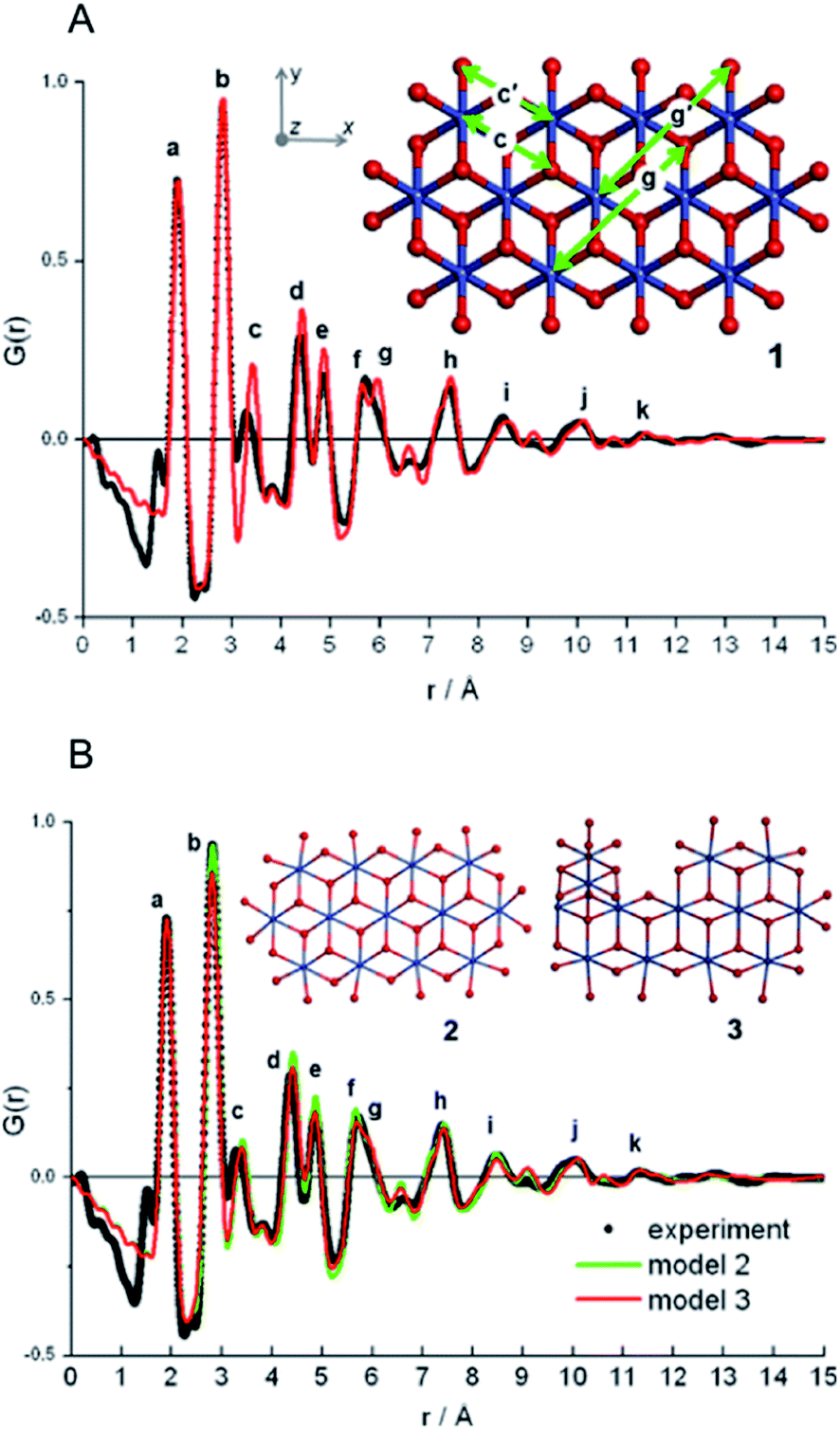
PDF has been used in a range of other defected oxide systems, where the ability to characterize local structure has allowed a description of the atomic arrangement.65,163–165 For example, ferrihydrite has been extensively studied with X-ray and neutron PDF over the last decade.166–168 In a 2007 paper, Michel et al. suggested a ferrihydrite structure using X-ray PDF, which resembles a Baker–Figgis δ-Keggin cluster structural motif.166,168 After some controversy regarding this model, the structure of ferrihydrite was further analyzed by Harrington et al. using neutron total scattering with PDF analysis. They found that the single phase model containing a Keggin motif best described the data compared to other 2-phase models proposed in the literature.167 As an important point, the authors emphasized that the model is merely a representation of the ensemble average structure: When characterizing highly defective nanoscale materials, any simple model will be unlikely to fully describe the structures in samples with e.g. a distribution of crystallite domain sizes and structures that are difficult to parameterize. A model for such disordered systems should be seen as describing the most important structural motifs and as a starting point for further analysis. In order to better understand ferrihydrite, recent work was done concerning the structure of an aluminum analog to ferrihydrite, akdalaite. The structure of akdalaite was determined by single crystal X-ray diffraction, neutron diffraction and NMR,169 and it was shown to contain a Keggin cluster motif. The calculated PDF of the akdalaite structure was then compared to the experimental PDF of 6-line ferrihydrite and it was found to describe the major structural features, further suggesting that the structure of ferrihydrite resembles that of Keggin clusters. Very recently, Funnel et al. used a nanocomposite RMC methodology for further analysis of X-ray PDFs from ferrihydrite. Here, it was shown that the single phase model from Michel et al. gave the best fit to the data without any unphysical structural rearrangements.170
 | ||
| Fig. 12 Fits to PDF from nanostructured cobalt oxide. (A) Fit of the PDF from model 1 (red) to the experimental PDF (black). (B) Fit of the PDF from model 2 (red) and model 3 (green), compared to the experimental PDF in black. Rw is 0.27 for structure 1 and 0.19 for structures 2 and 3. Adapted with permission from Du et al., J. Am. Chem. Soc., 2012, 134, 11096–11099.175 Copyright 2012 American Chemical Society. | ||
The combination of PDF with other scattering techniques gives many possibilities for structural insight. Farrow et al. showed that complex modelling of combined SAXS and PDF data allowed a more robust characterization of CdS nanoparticle morphology187 as can be applied in Diffpy-CMI.62 Many more studies of this kind is likely to be seen in the literature in the future.
The complex challenges involved in structural characterization of disordered layered oxides are addressed in an extensive study of the structure of δ-MnO2 by Liu et al.199 Layered metal oxides are often small nanoparticles, contain turbostatic stacking faults and exhibit in-plane cation disorder. Liu et al. address all three aspects of the structural complexity in a study of Cu-rich δ-MnO2 (ref. 199) using X-ray total scattering and PDF, supported by a range of techniques, including EXAFS and neutron PDF. The local structure in the planes of the layered oxide was first determined by fitting the 0.7–8 Å range of the PDF. Cu2+ ions were localized in the structure by comparing a model where Cu2+ was placed in the Mn4+ sites of the layer, or a model where the Cu2+ was placed between the layers of the structure. It was found that the Cu2+ ions sit in interplanar sites above or below a vacant Mn4+ site. Next, the in-plane vacancy ordering was determined by comparing fits of different cation vacancy ordering models applied only to the local range of the PDF, where only intraplanar distances are represented. A chalcophanite structure model with 7.2% Mn vacancy was found to most suitably describe the in-plane atomic arrangement, with a good agreement factor of 8.2%. The local structure description is further extended by locating the interlayer H2O using neutron PDF, which is possible due to the greater sensitivity to H (or D) when using neutrons instead of X-rays in a scattering experiment. Finally, using the local atomic structure model already developed, a model for the stacking disorder was built by creating a supercell containing 7 layers with the refined local layer structure. Each layer was assigned three vectors (ta, tb, tc), one for each crystallographic axis, that allowed the atomic structure in the layer to remain unchanged, while the layers can move with respect to each other. Furthermore, a numerical particle shape correction was applied that replaced the usual spherical envelope function and improves the long-range fit of the PDF for the non-spherical particles.63 The final stacking fault model provided a good description of scattering data in both Q and r for both X-rays and neutrons. The refined values of the in-plane layer vectors (ta and tb), appeared largely random, while the vectors in the stacking direction remained unchanged, which was interpreted as the stacking faults being associated with rotational disorder. This study showcases a highly inventive way of extending the local structural information available in the PDF to describe the full nanostructure of a complex sample.
In situ and operando experiments: changes in nanoparticle structure
Having established the strength of PDF analysis for nanomaterial characterization, we here only briefly mention the importance of in situ and operando PDF analysis in nanomaterials chemistry, as these fields have been reviewed in the past.32,33,37In situ X-ray or neutron powder diffraction, where diffraction patterns are continuously collected during a chemical reaction, has a long and successful history dating back to the 1990s, and excels when investigating bulk crystalline phase transitions and crystallite growth kinetics.203–206In situ PDF studies, on the other hand, allow for identification and characterization of disordered or amorphous intermediate structures and species in solution, which are important in nanomaterials. For example, in studies of nanomaterial synthesis, in situ PDF analysis gives the possibility for studying the atomic structure of the species present before, during and after crystallization of nanoparticles,183,207–219 which is essential for gaining a deeper understanding of material nucleation processes, where atomic scale mechanistic information generally is scarce. Knowledge of the relation between chemical synthesis and the resulting atomic structure of the material is crucial in the advancement of nanoscience.220 In studies of battery materials, operando experiments allow following the changes in electrode structure during operation, and the use of PDF has revealed complex reactions, where disordered nanomaterials play a large role in the cycling processes.221–229Summary and future perspectives
We have reviewed a number of studies where atomic structure on the nanoscale has been characterized using PDF. Structural studies of metals, chalcogenides and oxides were described, covering a range of different approaches to PDF analysis, including model-free analysis, real-space Rietveld refinement, d-PDF analysis, and modelling using discrete structures with the Debye scattering equation. The PDF technique is growing in importance, and many other emerging nanomaterials such as perovskites,36,230–232 upconverting nanoparticles,34,233 sulfides,234–236 nitrides and carbides237–242 are now being investigated with PDF. The diversity of the studies demonstrates an important point: there is no one-fits-all approach to PDF modelling of the structure of nanoparticles, and the method to be used is dependent on the problem that is under investigation, and what information is sought. This means that constructing a good structural model for a nanostructure from PDF analysis requires a great deal of creativity, structural understanding and chemical intuition, however the simplicity and intuitive nature of the PDF can be helpful in achieving a good starting point.While PDF analysis can be extremely useful for analysis of atomic structure, one always has to be aware of its limitations: the PDF will not always contain enough information to determine a unique model for atomic structure. This problem is only amplified by the disordered and polydisperse nature of most nanomaterials, and careful consideration should be given to the uniqueness and validity of any model constructed. It is paramount that PDF models are supported by structural information from other techniques. One perspective on tackling this issue is the complex modelling approach, where one structural model is refined against multiple datasets from different techniques.62,73,243 This makes the models and refined parameters more reliable, as they have been constrained by structural information obtained from techniques with different strengths and weaknesses, such as when combining PDF or total scattering with SAXS95,187,244 or EXAFS data.74,245
The interest and development of advanced computational techniques such as database mining and machine learning are very likely to impact PDF analysis as well as many other data-heavy fields in the coming years.246 For example, machine learning methods have already been applied to PDF in regards to component analysis123,247–250 and in identifying symmetry and extracting distance lists.251,252 This development is likely to aid in maximizing the information that can be extracted from the PDF of complicated nanostructures. Automated modelling, where large numbers of structures (mined from databases or algorithmically generated) are fitted to experimental PDFs, can improve the structural characterization workflow and the discovery of new and improved models.127,128,253 However, presently, the more advanced tools for modelling and constructing new nanostructures are somewhat un-accessible to the broad scientific community, and the development of user-friendly software and tools for more advanced analysis should be a high priority within the PDF community.
While these new advanced developments are hugely important, we stress that significant information can be extracted from PDF analysis using relatively simple methods, such as real-space Rietveld refinement or model-free analysis of individual peaks, and PDF will prove useful in the toolbox of any scientist wishing to characterize nanostructures. With this review, we hope to have provided an entry into PDF analysis, and we invite everyone to join the journey down the yellow brick road towards better understanding of structure on the nanoscale.
Conflicts of interest
There are no conflicts to declare.Acknowledgements
We are grateful to the Villum Foundation for financial support through a Villum Young Investigator grant. KMØJ acknowledges funding from the Danish Research Council under the Sapere Aude Research Talent Program. This work is part of a project that has received funding from the European Research Council (ERC) under the European Union's Horizon 2020 research and innovation programme, (Grant agreement no. 804066). This project has received funding from the European Union's Horizon 2020 research and innovation programme under the Marie Sklodowska-Curie grant agreement no. 841903.References
- D. Schwarzenbach, Acta Crystallogr., Sect. A: Found. Crystallogr., 2012, 68, 57–67 CrossRef CAS PubMed.
- Nat. Mater., 2014, 13, 757 Search PubMed.
- M. Eckert, Acta Crystallogr., Sect. A: Found. Crystallogr., 2012, 68, 30–39 CrossRef CAS PubMed.
- W. L. Bragg, Proc. R. Soc. London, Ser. A, 1913, 89, 248–277 CAS.
- W. Friedrich, P. Knipping and M. Laue, Ann. Phys., 1913, 346, 971–988 CrossRef.
- H. M. Rietveld, J. Appl. Crystallogr., 1969, 2, 65–71 CrossRef CAS.
- A. K. Cheetham and A. L. Goodwin, Nat. Mater., 2014, 13, 760–762 CrossRef CAS PubMed.
- M. Etter and R. E. Dinnebier, Z. Anorg. Allg. Chem., 2014, 640, 3015–3028 CrossRef CAS.
- J. Wood, Mater. Today, 2008, 11, 40–45 CrossRef CAS.
- W. J. Stark, P. R. Stoessel, W. Wohlleben and A. Hafner, Chem. Soc. Rev., 2015, 44, 5793–5805 RSC.
- M. V. Kovalenko, L. Manna, A. Cabot, Z. Hens, D. V. Talapin, C. R. Kagan, V. I. Klimov, A. L. Rogach, P. Reiss, D. J. Milliron, P. Guyot-Sionnnest, G. Konstantatos, W. J. Parak, T. Hyeon, B. A. Korgel, C. B. Murray and W. Heiss, ACS Nano, 2015, 9, 1012–1057 CrossRef CAS PubMed.
- E. Roduner, Chem. Soc. Rev., 2006, 35, 583–592 RSC.
- V. H. Grassian, J. Phys. Chem. C, 2008, 112, 18303–18313 CrossRef CAS.
- M. Auffan, J. Rose, J.-Y. Bottero, G. V. Lowry, J.-P. Jolivet and M. R. Wiesner, Nat. Nanotechnol., 2009, 4, 634–641 CrossRef CAS PubMed.
- C. L. Cleveland, U. Landman, T. G. Schaaff, M. N. Shafigullin, P. W. Stephens and R. L. Whetten, Phys. Rev. Lett., 1997, 79, 1873–1876 CrossRef CAS.
- N. Goswami, Q. Yao, T. Chen and J. Xie, Coord. Chem. Rev., 2016, 329, 1–15 CrossRef CAS.
- H. Qian, M. Zhu, Z. Wu and R. Jin, Acc. Chem. Res., 2012, 45, 1470–1479 CrossRef CAS PubMed.
- E. C. Tyo and S. Vajda, Nat. Nanotechnol., 2015, 10, 577–588 CrossRef CAS PubMed.
- S. J. L. Billinge and I. Levin, Science, 2007, 316, 561–565 CrossRef CAS PubMed.
- B. Ingham, Crystallogr. Rev., 2015, 21, 229–303 CrossRef.
- D. Balzar, N. Audebrand, M. R. Daymond, A. Fitch, A. Hewat, J. I. Langford, A. Le Bail, D. Louer, O. Masson, C. N. McCowan, N. C. Popa, P. W. Stephens and B. H. Toby, J. Appl. Crystallogr., 2004, 37, 911–924 CrossRef CAS.
- T. Egami and S. J. Billinge, Underneath the Bragg peaks: Structural analysis of complex materials, Elsevier, Amsterdam, 2nd edn, 2012 Search PubMed.
- E. K. Richman and J. E. Hutchison, ACS Nano, 2009, 3, 2441–2446 CrossRef CAS PubMed.
- A. Kuzmin and J. Chaboy, IUCrJ, 2014, 1, 571–589 CrossRef CAS PubMed.
- J. Miao, P. Ercius and S. J. L. Billinge, Science, 2016, 353, aaf2157 CrossRef PubMed.
- Y. Yang, C.-C. Chen, M. C. Scott, C. Ophus, R. Xu, A. Pryor, L. Wu, F. Sun, W. Theis, J. Zhou, M. Eisenbach, P. R. C. Kent, R. F. Sabirianov, H. Zeng, P. Ercius and J. Miao, Nature, 2017, 542, 75–79 CrossRef CAS PubMed.
- D. A. Muller, Nat. Mater., 2009, 8, 263–270 CrossRef CAS PubMed.
- S. J. L. Billinge and M. G. Kanatzidis, Chem. Commun., 2004, 7, 749–760 RSC.
- K. Page, T. Proffen and R. Neder, in Modern Diffraction Methods, ed. E. J. Mittemeijer and U. Welzel, 2013, pp. 61–86, DOI:10.1002/9783527649884.ch3.
- T. Egami, H. D. Rosenfeld, B. H. Toby and A. Bhalla, Ferroelectrics, 1991, 120, 11–21 CrossRef CAS.
- S. J. L. Billinge, Philos. Trans. R. Soc. London, Ser. A, 2019, 377, 20180413 CrossRef CAS PubMed.
- E. D. Bøjesen and B. B. Iversen, CrystEngComm, 2016, 18, 8332–8353 RSC.
- K. W. Chapman, MRS Bull., 2016, 41, 231–240 CrossRef.
- S. S. Perera, D. K. Amarasinghe, K. T. Dissanayake and F. A. Rabuffetti, Chem. Mater., 2017, 29, 6289–6297 CrossRef CAS.
- R. B. Soriano, I. U. Arachchige, C. D. Malliakas, J. Wu and M. G. Kanatzidis, J. Am. Chem. Soc., 2013, 135, 768–774 CrossRef CAS PubMed.
- F. A. Rabuffetti and R. L. Brutchey, ACS Nano, 2013, 7, 11435–11444 CrossRef CAS PubMed.
- K. M. Ø. Jensen, C. Tyrsted, M. Bremholm and B. B. Iversen, ChemSusChem, 2014, 7, 1594–1611 CrossRef CAS PubMed.
- R. Harrington, D. B. Hausner, N. Bhandari, D. R. Strongin, K. W. Chapman, P. J. Chupas, D. S. Middlemiss, C. P. Grey and J. B. Parise, Inorg. Chem., 2010, 49, 325–330 CrossRef CAS PubMed.
- X. Wang, J. D. Kubicki, J.-F. Boily, G. A. Waychunas, Y. Hu, X. Feng and M. Zhu, ACS Earth Space Chem., 2018, 2, 125–134 CrossRef CAS.
- R. Harrington, R. B. Neder and J. B. Parise, Chem. Geol., 2012, 329, 3–9 CrossRef CAS.
- S. Thakral, M. W. Terban, N. K. Thakral and R. Suryanarayanan, Adv. Drug Delivery Rev., 2016, 100, 183–193 CrossRef CAS PubMed.
- S. J. L. Billinge, Nanomedicine, 2015, 10, 2473–2475 CrossRef CAS PubMed.
- M. W. Terban, M. Johnson, M. Di Michiel and S. J. L. Billinge, Nanoscale, 2015, 7, 5480–5487 RSC.
- P. J. Chupas, X. Y. Qiu, J. C. Hanson, P. L. Lee, C. P. Grey and S. J. L. Billinge, J. Appl. Crystallogr., 2003, 36, 1342–1347 CrossRef CAS.
- C. L. Farrow, P. Juhas, J. W. Liu, D. Bryndin, E. S. Bozin, J. Bloch, T. Proffen and S. J. L. Billinge, J. Phys.: Condens. Matter, 2007, 19, 335219 CrossRef CAS PubMed.
- P. Juhas, T. Davis, C. L. Farrow and S. J. L. Billinge, J. Appl. Crystallogr., 2013, 46, 560–566 CrossRef CAS.
- A. A. Coelho, P. A. Chater and A. Kern, J. Appl. Crystallogr., 2015, 48, 869–875 CrossRef CAS.
- A. K. Soper, GudrunN and GudrunX: programs for correcting raw neutron and X-ray diffraction data to differential scattering cross section, Science & Technology Facilities Council Swindon, UK, 2011 Search PubMed.
- B. H. Toby and R. B. Von Dreele, J. Appl. Crystallogr., 2013, 46, 544–549 CrossRef CAS.
- S. J. L. Billinge, Z. Kristallogr., 2004, 219, 117–121 CAS.
- C. A. Young and A. L. Goodwin, J. Mater. Chem., 2011, 21, 6464–6476 RSC.
- T. Proffen, K. L. Page, S. E. McLain, B. Clausen, T. W. Darling, J. A. TenCate, S. Y. Lee and E. Ustundag, Z. Kristallogr., 2005, 220, 1002–1008 CAS.
- A. S. Masadeh, J. Exp. Nanosci., 2016, 11, 951–974 CrossRef CAS.
- P. Bordet, C. R. Phys., 2018, 19, 561–574 CrossRef CAS.
- T. Proffen, S. J. L. Billinge, T. Egami and D. Louca, Z. Kristallogr., 2003, 218, 132–143 CAS.
- S. J. L. Billinge and R. E. Dinnebier, Powder Diffraction: Theory and Practice, RSC Publishing, Cambridge, 2008 Search PubMed.
- P. F. Peterson, M. Gutmann, T. Proffen and S. J. L. Billinge, J. Appl. Crystallogr., 2000, 33, 1192 CrossRef CAS.
- P. Juhas, J. N. Louwen, L. van Eijck, E. T. C. Vogt and S. J. L. Billinge, J. Appl. Crystallogr., 2018, 51, 1492–1497 CrossRef CAS.
- S. L. J. Thomae, N. Prinz, T. Hartmann, M. Teck, S. Correll and M. Zobel, Rev. Sci. Instrum., 2019, 90, 043905 CrossRef PubMed.
- A. M. M. Abeykoon, C. D. Malliakas, P. Juhás, E. S. Bozin, M. G. Kanatzidis and S. J. L. Billinge, Z. Kristallogr. - Cryst. Mater., 2012, 227, 248 CrossRef.
- D. Keen, J. Appl. Crystallogr., 2001, 34, 172–177 CrossRef CAS.
- P. Juhas, C. L. Farrow, X. Yang, K. R. Knox and S. J. L. Billinge, Acta Crystallogr., Sect. A: Found. Adv., 2015, 71, 562–568 CrossRef PubMed.
- T.-M. Usher, D. Olds, J. Liu and K. Page, Acta Crystallogr., Sect. A: Found. Adv., 2018, 74, 322–331 CrossRef CAS PubMed.
- L. Gamez-Mendoza, M. W. Terban, S. J. L. Billinge and M. Martinez-Inesta, J. Appl. Crystallogr., 2017, 50, 741–748 CrossRef CAS.
- G. Paglia, E. S. Bozin and S. J. L. Billinge, Chem. Mater., 2006, 18, 3242–3248 CrossRef CAS.
- P. Debye and P. Scherrer, Phys. Z., 1916, 17, 277–283 CAS.
- B. D. Hall and R. Monot, Comput. Phys., 1991, 5, 414–417 CrossRef.
- T. Proffen and R. B. Neder, J. Appl. Crystallogr., 1997, 30, 171–175 CrossRef CAS.
- F. Bertolotti, D. Moscheni, A. Guagliardi and N. Masciocchi, Eur. J. Inorg. Chem., 2018, 2018, 3789–3803 CrossRef CAS.
- A. Cervellino, R. Frison, F. Bertolotti and A. Guagliardi, J. Appl. Crystallogr., 2015, 48, 1600–5767 CrossRef.
- M. G. Tucker, D. A. Keen, M. T. Dove, A. L. Goodwin and Q. Hui, J. Phys.: Condens. Matter, 2007, 19, 335218 CrossRef PubMed.
- M. T. Dove, M. G. Tucker and D. A. Keen, Eur. J. Mineral., 2002, 14, 331–348 CrossRef CAS.
- M. J. Cliffe, M. T. Dove, D. Drabold and A. L. Goodwin, Phys. Rev. Lett., 2010, 104, 125501 CrossRef PubMed.
- M. Harada, R. Ikegami, L. S. R. Kumara, S. Kohara and O. Sakata, RSC Adv., 2019, 9, 29511–29521 RSC.
- V. Petkov, C. M. Hessel, J. Ovtchinnikoff, A. Guillaussier, B. A. Korgel, X. Liu and C. Giordano, Chem. Mater., 2013, 25, 2365–2371 CrossRef CAS.
- J. A. Vargas, V. Petkov, E. S. A. Nouh, R. K. Ramamoorthy, L.-M. Lacroix, R. Poteau, G. Viau, P. Lecante and R. Arenal, ACS Nano, 2018, 12, 9521–9531 CrossRef CAS PubMed.
- V. Petkov, S. J. L. Billinge, P. Larson, S. D. Mahanti, T. Vogt, K. K. Rangan and M. G. Kanatzidis, Phys. Rev. B: Condens. Matter Mater. Phys., 2002, 65, 092105 CrossRef.
- V. Petkov, S. J. L. Billinge, J. Heising and M. G. Kanatzidis, J. Am. Chem. Soc., 2000, 122, 11571–11576 CrossRef CAS.
- R. B. Neder and V. I. Korsunskiy, J. Phys.: Condens. Matter, 2005, 17, S125–S134 CrossRef CAS.
- V. I. Korsounski, R. B. Neder, K. Hradil, C. Barglik-Chory, G. Muller and J. Neuefeind, J. Appl. Crystallogr., 2003, 36, 1389–1396 CrossRef CAS.
- D. C. Gary, M. W. Terban, S. J. L. Billinge and B. M. Cossairt, Chem. Mater., 2015, 27, 1432–1441 CrossRef CAS.
- A. Demortière, D. N. Leonard, V. Petkov, K. Chapman, S. Chattopadhyay, C. She, D. A. Cullen, T. Shibata, M. Pelton and E. V. Shevchenko, J. Phys. Chem. Lett., 2018, 9, 1900–1906 CrossRef PubMed.
- J. Owen and L. Brus, J. Am. Chem. Soc., 2017, 139, 10939–10943 CrossRef CAS PubMed.
- A. Eychmüller, J. Phys. Chem. B, 2000, 104, 6514–6528 CrossRef.
- S. M. Harrell, J. R. McBride and S. J. Rosenthal, Chem. Mater., 2013, 25, 1199–1210 CrossRef CAS.
- A. S. Masadeh, E. S. Bozin, C. L. Farrow, G. Paglia, P. Juhas, S. J. L. Billinge, A. Karkamkar and M. G. Kanatzidis, Phys. Rev. B, 2007, 76, 115413 CrossRef.
- C. B. Murray, D. J. Norris and M. G. Bawendi, J. Am. Chem. Soc., 1993, 115, 8706–8715 CrossRef CAS.
- M. G. Bawendi, A. R. Kortan, M. L. Steigerwald and L. E. Brus, J. Chem. Phys., 1989, 91, 7282–7290 CrossRef CAS.
- X. Yang, A. S. Masadeh, J. R. McBride, E. S. Božin, S. J. Rosenthal and S. J. L. Billinge, Phys. Chem. Chem. Phys., 2013, 15, 8480–8486 RSC.
- W. Vogel, P. H. Borse, N. Deshmukh and S. K. Kulkarni, Langmuir, 2000, 16, 2032–2037 CrossRef CAS.
- P.-J. Wu, Y. P. Stetsko, K.-D. Tsuei, R. Dronyak and K. S. Liang, Appl. Phys. Lett., 2007, 90, 161911 CrossRef.
- C. Kumpf, R. B. Neder, F. Niederdraenk, P. Luczak, A. Stahl, M. Scheuermann, S. Joshi, S. K. Kulkarni, C. Barglik-Chory, C. Heske and E. Umbach, J. Chem. Phys., 2005, 123, 224707 CrossRef CAS PubMed.
- F. Bertolotti, A. H. Proppe, D. N. Dirin, M. Liu, O. Voznyy, A. Cervellino, S. J. L. Billinge, M. V. Kovalenko, E. H. Sargent, N. Masciocchi and A. Guagliardi, Chem. Sq., 2018, 2, 1 Search PubMed.
- R. B. Neder, V. I. Korsunskiy, C. Chory, G. Müller, A. Hofmann, S. Dembski, C. Graf and E. Rühl, Phys. Status Solidi C, 2007, 4, 3221–3233 CrossRef CAS.
- D. Moscheni, F. Bertolotti, L. Piveteau, L. Protesescu, D. N. Dirin, M. V. Kovalenko, A. Cervellino, J. S. Pedersen, N. Masciocchi and A. Guagliardi, ACS Nano, 2018, 12, 12558–12570 CrossRef CAS PubMed.
- F. Niederdraenk, K. Seufert, A. Stahl, R. S. Bhalerao-Panajkar, S. Marathe, S. K. Kulkarni, R. B. Neder and C. Kumpf, Phys. Chem. Chem. Phys., 2011, 13, 498–505 RSC.
- F. Niederdraenk, K. Seufert, P. Luczak, S. K. Kulkarni, C. Chory, R. B. Neder and C. Kumpf, Phys. Status Soldi C, 2007, 4, 3234–3243 CrossRef CAS.
- E. S. Bozin, C. D. Malliakas, P. Souvatzis, T. Proffen, N. A. Spaldin, M. G. Kanatzidis and S. J. L. Billinge, Science, 2010, 330, 1660–1663 CrossRef CAS PubMed.
- F. Bertolotti, D. N. Dirin, M. Ibáñez, F. Krumeich, A. Cervellino, R. Frison, O. Voznyy, E. H. Sargent, M. V. Kovalenko, A. Guagliardi and N. Masciocchi, Nat. Mater., 2016, 15, 987–994 CrossRef CAS PubMed.
- K. Yu, Adv. Mater., 2012, 24, 1123–1132 CrossRef CAS PubMed.
- A. N. Beecher, X. Yang, J. H. Palmer, A. L. LaGrassa, P. Juhas, S. J. L. Billinge and J. S. Owen, J. Am. Chem. Soc., 2014, 136, 10645–10653 CrossRef CAS PubMed.
- J. L. Stein, M. I. Steimle, M. W. Terban, A. Petrone, S. J. L. Billinge, X. Li and B. M. Cossairt, Chem. Mater., 2017, 29, 7984–7992 CrossRef CAS.
- L. Tan, A. J. Misquitta, A. Sapelkin, L. Fang, R. M. Wilson, D. S. Keeble, B. Zhang, T. Zhu, F. S. Riehle, S. Han, K. Yu and M. T. Dove, Nanoscale, 2019, 11, 21900–21908 RSC.
- B. Gilbert, F. Huang, H. Zhang, G. A. Waychunas and J. F. Banfield, Science, 2004, 305, 651–654 CrossRef CAS PubMed.
- G. R. Schleder, G. M. Azevedo, I. C. Nogueira, Q. H. F. Rebelo, J. Bettini, A. Fazzio and E. R. Leite, J. Phys. Chem. Lett., 2019, 10, 1471–1476 CrossRef CAS PubMed.
- B. M. Cossairt, P. Juhas, S. J. L. Billinge and J. S. Owen, J. Phys. Chem. Lett., 2011, 2, 3075–3080 CrossRef CAS PubMed.
- H.-W. Wang, D. J. Wesolowski, T. E. Proffen, L. Vlcek, W. Wang, L. F. Allard, A. I. Kolesnikov, M. Feygenson, L. M. Anovitz and R. L. Paul, J. Am. Chem. Soc., 2013, 135, 6885–6895 CrossRef CAS PubMed.
- H. Zhang, B. Gilbert, F. Huang and J. F. Banfield, Nature, 2003, 424, 1025–1029 CrossRef CAS PubMed.
- R. Sardar, A. M. Funston, P. Mulvaney and R. W. Murray, Langmuir, 2009, 25, 13840–13851 CrossRef CAS PubMed.
- C. Xie, Z. Niu, D. Kim, M. Li and P. Yang, Chem. Rev., 2020, 120, 1184–1249 CrossRef CAS PubMed.
- T. Ishida, T. Murayama, A. Taketoshi and M. Haruta, Chem. Rev., 2020, 120, 464–525 CrossRef CAS PubMed.
- L. D. Marks and A. Howie, Nature, 1979, 282, 196–198 CrossRef CAS.
- L. D. Marks, Rep. Prog. Phys., 1994, 57, 603–649 CrossRef CAS.
- A. Mackay, Acta Crystallogr., 1962, 15, 916–918 CrossRef CAS.
- S. Hajiw, B. Pansu and J.-F. Sadoc, ACS Nano, 2015, 9, 8116–8121 CrossRef CAS PubMed.
- F. C. Frank and J. S. Kasper, Acta Crystallogr., 1959, 12, 483–499 CrossRef CAS.
- H. Nakotte, C. Silkwood, K. Page, H. W. Wang, D. Olds, B. Kiefer, S. Manna, D. Karpov, E. Fohtung and E. E. Fullerton, Phys. Scr., 2017, 92, 114002 CrossRef.
- S. Ino, J. Phys. Soc. Jpn., 1969, 27, 941–953 CrossRef CAS.
- L. D. Marks, J. Cryst. Growth, 1983, 61, 556–566 CrossRef CAS.
- K. Page, T. Proffen, H. Terrones, M. Terrones, L. Lee, Y. Yang, S. Stemmer, R. Seshadri and A. K. Cheetham, Chem. Phys. Lett., 2004, 393, 385–388 CrossRef CAS.
- V. Petkov, Y. Peng, G. Williams, B. Huang, D. Tomalia and Y. Ren, Phys. Rev. B: Condens. Matter Mater. Phys., 2005, 72, 195402 CrossRef.
- A. Hjorth Larsen, J. Jørgen Mortensen, J. Blomqvist, I. E. Castelli, R. Christensen, M. Dułak, J. Friis, M. N. Groves, B. Hammer, C. Hargus, E. D. Hermes, P. C. Jennings, P. Bjerre Jensen, J. Kermode, J. R. Kitchin, E. Leonhard Kolsbjerg, J. Kubal, K. Kaasbjerg, S. Lysgaard, J. Bergmann Maronsson, T. Maxson, T. Olsen, L. Pastewka, A. Peterson, C. Rostgaard, J. Schiøtz, O. Schütt, M. Strange, K. S. Thygesen, T. Vegge, L. Vilhelmsen, M. Walter, Z. Zeng and K. W. Jacobsen, J. Phys.: Condens. Matter, 2017, 29, 273002 CrossRef PubMed.
- W. Li, O. J. Borkiewicz, M. Saubanère, M.-L. Doublet, D. Flahaut, P. J. Chupas, K. W. Chapman and D. Dambournet, J. Phys. Chem. C, 2018, 122, 23861–23866 CrossRef CAS.
- W. A. Sławiński, E. Zacharaki, H. Fjellvåg and A. O. Sjåstad, Cryst. Growth Des., 2018, 18, 2316–2325 CrossRef.
- J. A. Oberteuffer and J. A. Ibers, Acta Crystallogr., Sect. B: Struct. Crystallogr. Cryst. Chem., 1970, 26, 1499–1504 CrossRef CAS.
- S. Banerjee, C.-H. Liu, J. D. Lee, A. Kovyakh, V. Grasmik, O. Prymak, C. Koenigsmann, H. Liu, L. Wang, A. M. M. Abeykoon, S. S. Wong, M. Epple, C. B. Murray and S. J. L. Billinge, J. Phys. Chem. C, 2018, 122, 29498–29506 CrossRef CAS.
- S. Banerjee, C.-H. Liu, K. M. Ø. Jensen, P. Juhas, J. D. Lee, M. Tofanelli, C. J. Ackerson, C. B. Murray and S. J. L. Billinge, Acta Crystallogr., Sect. A: Found. Adv., 2020, 76, 24–31 CrossRef CAS PubMed.
- T. Lindahl Christiansen, E. T. S. Kjær, A. Kovyakh, M. L. Röderen, M. Høj, T. Vosch and K. M. Ø. Jensen, J. Appl. Crystallogr., 2020, 53, 148–158 CrossRef CAS PubMed.
- V. V. T. Doan-Nguyen, S. A. J. Kimber, D. Pontoni, D. Reifsnyder Hickey, B. T. Diroll, X. Yang, M. Miglierini, C. B. Murray and S. J. L. Billinge, ACS Nano, 2014, 8, 6163–6170 CrossRef CAS PubMed.
- L. B. Skinner, C. J. Benmore, J. K. R. Weber, M. A. Williamson, A. Tamalonis, A. Hebden, T. Wiencek, O. L. G. Alderman, M. Guthrie, L. Leibowitz and J. B. Parise, Science, 2014, 346, 984–987 CrossRef CAS PubMed.
- T. Lindahl Christiansen, E. D. Bøjesen, M. Juelsholt, J. Etheridge and K. M. Ø. Jensen, ACS Nano, 2019, 13, 8725–8735 CrossRef PubMed.
- C. J. Benmore, ISRN Mater. Sci., 2012, 2012, 852905 Search PubMed.
- H. E. Fischer, A. C. Barnes and P. S. Salmon, Rep. Prog. Phys., 2005, 69, 233–299 CrossRef.
- R. Jin, C. Zeng, M. Zhou and Y. Chen, Chem. Rev., 2016, 116, 10346–10413 CrossRef CAS PubMed.
- R. Jin, Nanoscale, 2015, 7, 1549–1565 RSC.
- S. Tian, Y.-Z. Li, M.-B. Li, J. Yuan, J. Yang, Z. Wu and R. Jin, Nat. Commun., 2015, 6, 8667 CrossRef CAS PubMed.
- S. F. Li, X. J. Zhao, X. S. Xu, Y. F. Gao and Z. Zhang, Phys. Rev. Lett., 2013, 111, 115501 CrossRef CAS PubMed.
- C. Kumara, X. Zuo, D. A. Cullen and A. Dass, ACS Nano, 2014, 8, 6431–6439 CrossRef CAS PubMed.
- C. Kumara, X. Zuo, J. Ilavsky, K. W. Chapman, D. A. Cullen and A. Dass, J. Am. Chem. Soc., 2014, 136, 7410–7417 CrossRef CAS PubMed.
- K. M. Ø. Jensen, P. Juhas, M. A. Tofanelli, C. L. Heinecke, G. Vaughan, C. J. Ackerson and S. J. L. Billinge, Nat. Commun., 2016, 7, 11859 CrossRef CAS PubMed.
- D. Bahena, N. Bhattarai, U. Santiago, A. Tlahuice, A. Ponce, S. B. H. Bach, B. Yoon, R. L. Whetten, U. Landman and M. Jose-Yacaman, J. Phys. Chem. Lett., 2013, 4, 975–981 CrossRef CAS PubMed.
- S. J. Tauster, S. C. Fung, R. T. K. Baker and J. A. Horsley, Science, 1981, 211, 1121 CrossRef CAS PubMed.
- R. J. White, R. Luque, V. L. Budarin, J. H. Clark and D. J. Macquarrie, Chem. Soc. Rev., 2009, 38, 481–494 RSC.
- A. T. Bell, Science, 2003, 299, 1688–1691 CrossRef CAS PubMed.
- K. W. Chapman, P. J. Chupas and C. J. Kepert, J. Am. Chem. Soc., 2005, 127, 11232–11233 CrossRef CAS PubMed.
- K. W. Chapman, P. J. Chupas, E. R. Maxey and J. W. Richardson, Chem. Commun., 2006, 38, 4013–4015 RSC.
- P. J. Chupas, K. W. Chapman, H. Chen and C. P. Grey, Catal. Today, 2009, 145, 213–219 CrossRef CAS.
- M. A. Newton, K. W. Chapman, D. Thompsett and P. J. Chupas, J. Am. Chem. Soc., 2012, 134, 5036–5039 CrossRef CAS PubMed.
- P. J. Chupas, K. W. Chapman, G. Jennings, P. L. Lee and C. P. Grey, J. Am. Chem. Soc., 2007, 129, 13822–13824 CrossRef CAS PubMed.
- V. Petkov, Y. Maswadeh, A. Lu, S. Shan, H. Kareem, Y. Zhao, J. Luo, C.-J. Zhong, K. Beyer and K. Chapman, ACS Appl. Mater. Interfaces, 2018, 10, 10870–10881 CrossRef CAS PubMed.
- Y. Lei, H. Zhao, R. D. Rivas, S. Lee, B. Liu, J. Lu, E. Stach, R. E. Winans, K. W. Chapman, J. P. Greeley, J. T. Miller, P. J. Chupas and J. W. Elam, J. Am. Chem. Soc., 2014, 136, 9320–9326 CrossRef CAS PubMed.
- C. Y. Shi, E. L. Redmond, A. Mazaheripour, P. Juhas, T. F. Fuller and S. J. L. Billinge, J. Phys. Chem. C, 2013, 117, 7226–7230 CrossRef CAS.
- J. Quinson, L. Kacenauskaite, T. Lindahl Christiansen, T. Vosch, M. Arenz and K. M. Ø. Jensen, ACS Omega, 2018, 3, 10351–10356 CrossRef CAS PubMed.
- Y. Sun, N. Liu and Y. Cui, Nat. Energy, 2016, 1, 16071 CrossRef CAS.
- X. Chen, C. Li, M. Grätzel, R. Kostecki and S. S. Mao, Chem. Soc. Rev., 2012, 41, 7909–7937 RSC.
- B. R. Smith and S. S. Gambhir, Chem. Rev., 2017, 117, 901–986 CrossRef CAS PubMed.
- M. A. Shannon, P. W. Bohn, M. Elimelech, J. G. Georgiadis, B. J. Mariñas and A. M. Mayes, Nature, 2008, 452, 301–310 CrossRef CAS PubMed.
- D. Koziej, A. Lauria and M. Niederberger, Adv. Mater., 2014, 26, 235–257 CrossRef CAS PubMed.
- S. R. Cooper, L. K. Plummer, A. G. Cosby, P. Lenox, A. Jander, P. Dhagat and J. E. Hutchison, Chem. Mater., 2018, 30, 6053–6062 CrossRef CAS.
- D. Koziej, M. D. Rossell, B. Ludi, A. Hintennach, P. Novák, J.-D. Grunwaldt and M. Niederberger, Small, 2011, 7, 377–387 CrossRef CAS PubMed.
- Y. Chabre and J. Pannetier, Prog. Solid State Chem., 1995, 23, 1–130 CrossRef CAS.
- L. Kihlborg, in Nonstoichiometric Compounds, 1963, vol. 39, ch. 3, pp. 37–45 Search PubMed.
- A. L. Tiano, G. C. Papaefthymiou, C. S. Lewis, J. Han, C. Zhang, Q. Li, C. Y. Shi, A. M. M. Abeykoon, S. J. L. Billinge, E. Stach, J. Thomas, K. Guerrero, P. Munayco, J. Munayco, R. B. Scorzelli, P. Burnham, A. J. Viescas and S. S. Wong, Chem. Mater., 2015, 27, 3572–3592 CrossRef CAS.
- F. L. Deepak, M. Bañobre-López, E. Carbó-Argibay, M. F. Cerqueira, Y. Piñeiro-Redondo, J. Rivas, C. M. Thompson, S. Kamali, C. Rodríguez-Abreu, K. Kovnir and Y. V. Kolen'ko, J. Phys. Chem. C, 2015, 119, 11947–11957 CrossRef CAS.
- S. R. Cooper, R. O. Candler, A. G. Cosby, D. W. Johnson, K. M. Ø. Jensen and J. E. Hutchison, ACS Nano, 2020 DOI:10.1021/acsnano.9b09551.
- F. M. Michel, L. Ehm, S. M. Antao, P. L. Lee, P. J. Chupas, G. Liu, D. R. Strongin, M. A. A. Schoonen, B. L. Phillips and J. B. Parise, Science, 2007, 316, 1726–1729 CrossRef CAS PubMed.
- R. Harrington, D. B. Hausner, W. Xu, N. Bhandari, F. M. Michel, G. E. Brown, D. R. Strongin and J. B. Parise, Environ. Sci. Technol., 2011, 45, 9883–9890 CrossRef CAS PubMed.
- F. M. Michel, V. Barrón, J. Torrent, M. P. Morales, C. J. Serna, J.-F. Boily, Q. Liu, A. Ambrosini, A. C. Cismasu and G. E. Brown, Proc. Natl. Acad. Sci. U. S. A., 2010, 107, 2787–2792 CrossRef CAS PubMed.
- J. B. Parise, B. Xia, J. W. Simonson, W. R. Woerner, A. M. Plonka, B. L. Phillips and L. Ehm, Crystals, 2019, 9, 246 CrossRef CAS.
- N. P. Funnell, M. F. Fulford, S. Inoué, K. Kletetschka, F. M. Michel and A. L. Goodwin, Commun. Chem., 2020, 3, 22 CrossRef CAS.
- A. I. Nguyen, K. M. Van Allsburg, M. W. Terban, M. Bajdich, J. Oktawiec, J. Amtawong, M. S. Ziegler, J. P. Dombrowski, K. V. Lakshmi, W. S. Drisdell, J. Yano, S. J. L. Billinge and T. D. Tilley, Proc. Natl. Acad. Sci. U. S. A., 2019, 116, 11630–11639 CAS.
- J. Huang, J. D. Blakemore, D. Fazi, O. Kokhan, N. D. Schley, R. H. Crabtree, G. W. Brudvig and D. M. Tiede, Phys. Chem. Chem. Phys., 2014, 16, 1814–1819 RSC.
- A. S. Batchellor, G. Kwon, F. A. L. Laskowski, D. M. Tiede and S. W. Boettcher, J. Phys. Chem. C, 2017, 121, 25421–25429 CrossRef CAS.
- M. D. Donakowski, A. N. Mansour, I. R. Pala, C. N. Chervin, P. A. DeSario, J. W. Long and D. R. Rolison, J. Phys. Chem. C, 2018, 122, 28895–28900 CrossRef CAS.
- P. Du, O. Kokhan, K. W. Chapman, P. J. Chupas and D. M. Tiede, J. Am. Chem. Soc., 2012, 134, 11096–11099 CrossRef CAS PubMed.
- M. W. Kanan, J. Yano, Y. Surendranath, M. Dincă, V. K. Yachandra and D. G. Nocera, J. Am. Chem. Soc., 2010, 132, 13692–13701 CrossRef CAS PubMed.
- X. Chen and A. Selloni, Chem. Rev., 2014, 114, 9281–9282 CrossRef CAS PubMed.
- X. Chen and S. S. Mao, Chem. Rev., 2007, 107, 2891–2959 CrossRef CAS PubMed.
- N. Lock, E. M. L. Jensen, J. L. Mi, A. Mamakhel, K. Noren, Q. B. Meng and B. B. Iversen, Dalton Trans., 2013, 42, 9555–9564 RSC.
- W. Li, D. Corradini, M. Body, C. Legein, M. Salanne, J. Ma, K. W. Chapman, P. J. Chupas, A.-L. Rollet, C. Julien, K. Zhagib, M. Duttine, A. Demourgues, H. Groult and D. Dambournet, Chem. Mater., 2015, 27, 5014–5019 CrossRef CAS.
- W. Li, M. Body, C. Legein, O. J. Borkiewicz and D. Dambournet, Inorg. Chem., 2016, 55, 7182–7187 CrossRef CAS PubMed.
- W. Li, M. Body, C. Legein, O. J. Borkiewicz and D. Dambournet, Eur. J. Inorg. Chem., 2017, 192–197 CrossRef CAS.
- J.-L. Mi, K. M. Ø. Jensen, C. Tyrsted, M. Bremholm and B. B. Iversen, CrystEngComm, 2015, 17, 6868–6877 RSC.
- S. Banerjee, A. Zangiabadi, A. Mahdavi-Shakib, S. Husremovic, B. G. Frederick, K. Barmak, R. N. Austin and S. J. L. Billinge, ACS Appl. Nano Mater., 2019, 2, 6268–6276 CrossRef CAS.
- H. Zhang and J. F. Banfield, Chem. Rev., 2014, 114, 9613–9644 CrossRef CAS PubMed.
- X. Hua, Z. Liu, P. G. Bruce and C. P. Grey, J. Am. Chem. Soc., 2015, 137, 13612–13623 CrossRef CAS PubMed.
- C. L. Farrow, C. Shi, P. Juhas, X. Peng and S. J. L. Billinge, J. Appl. Crystallogr., 2014, 47, 561–565 CrossRef CAS.
- P. J. Chupas, K. W. Chapman and G. J. Halder, J. Am. Chem. Soc., 2011, 133, 8522–8524 CrossRef CAS PubMed.
- C. M. van Genuchten and J. Pena, Environ. Sci.: Processes Impacts, 2016, 18, 1030–1041 RSC.
- W. Li, R. Harrington, Y. Tang, J. D. Kubicki, M. Aryanpour, R. J. Reeder, J. B. Parise and B. L. Phillips, Environ. Sci. Technol., 2011, 45, 9687–9692 CrossRef CAS PubMed.
- C. M. van Genuchten and J. Peña, Chem. Geol., 2016, 429, 1–9 CrossRef CAS.
- M. H. Han, E. Gonzalo, G. Singh and T. Rojo, Energy Environ. Sci., 2015, 8, 81–102 RSC.
- N. A. Chernova, M. Roppolo, A. C. Dillon and M. S. Whittingham, J. Mater. Chem., 2009, 19, 2526–2552 RSC.
- M. P. Browne, Z. Sofer and M. Pumera, Energy Environ. Sci., 2019, 12, 41–58 RSC.
- W. He, K. Ai, X. Ren, S. Wang and L. Lu, J. Mater. Chem. A, 2017, 5, 19593–19606 RSC.
- R. Uppuluri, A. Sen Gupta, A. S. Rosas and T. E. Mallouk, Chem. Soc. Rev., 2018, 47, 2401–2430 RSC.
- D. S. Charles, M. Feygenson, K. Page, J. Neuefeind, W. Xu and X. Teng, Nat. Commun., 2017, 8, 15520 CrossRef CAS PubMed.
- B. Song, M. Tang, E. Hu, O. J. Borkiewicz, K. M. Wiaderek, Y. Zhang, N. D. Phillip, X. Liu, Z. Shadike, C. Li, L. Song, Y.-Y. Hu, M. Chi, G. M. Veith, X.-Q. Yang, J. Liu, J. Nanda, K. Page and A. Huq, Chem. Mater., 2019, 31, 3756–3765 CrossRef CAS.
- J. Liu, L. Yu, E. Hu, B. S. Guiton, X.-Q. Yang and K. Page, Inorg. Chem., 2018, 57, 6873–6882 CrossRef CAS PubMed.
- M. S. Hvid, H. S. Jeppesen, M. Miola, P. Lamagni, R. Su, K. M. Ø. Jensen and N. Lock, IUCrJ, 2019, 6, 804–814 CrossRef CAS PubMed.
- P. Gao, P. Metz, T. Hey, Y. Gong, D. Liu, D. D. Edwards, J. Y. Howe, R. Huang and S. T. Misture, Nat. Commun., 2017, 8, 14559 CrossRef CAS PubMed.
- P. C. Metz, R. Koch and S. T. Misture, J. Appl. Crystallogr., 2018, 51, 1437–1444 CrossRef CAS.
- H. L. Andersen, K. M. Ø. Jensen, C. Tyrsted, E. D. Bøjesen and M. Christensen, Cryst. Growth Des., 2014, 14, 1307–1313 CrossRef CAS.
- K. J. Gross, S. Guthrie, S. Takara and G. Thomas, J. Alloys Compd., 2000, 297, 270–281 CrossRef CAS.
- T. Ressler, R. E. Jentoft, J. Wienold, M. M. Günter and O. Timpe, J. Phys. Chem. B, 2000, 104, 6360–6370 CrossRef CAS.
- P. Norby, J. Am. Chem. Soc., 1997, 119, 5215–5221 CrossRef CAS.
- K. M. Ø. Jensen, M. Christensen, P. Juhas, C. Tyrsted, E. D. Bøjesen, N. Lock, S. J. L. Billinge and B. B. Iversen, J. Am. Chem. Soc., 2012, 134, 6785–6792 CrossRef CAS PubMed.
- C. Tyrsted, K. M. Ø. Jensen, E. D. Bøjesen, N. Lock, M. Christensen, S. J. L. Billinge and B. B. Iversen, Angew. Chem., Int. Ed., 2012, 51, 9030–9033 CrossRef CAS PubMed.
- C. Tyrsted, N. Lock, K. M. Ø. Jensen, M. Christensen, E. D. Bojesen, H. Emerich, G. Vaughan, S. J. L. Billinge and B. B. Iversen, IUCrJ, 2014, 1, 165–171 CrossRef CAS PubMed.
- K. M. Ø. Jensen, H. L. Andersen, C. Tyrsted, E. D. Bøjesen, A.-C. Dippel, N. Lock, S. J. L. Billinge, B. B. Iversen and M. Christensen, ACS Nano, 2014, 8, 10704–10714 CrossRef CAS PubMed.
- C. E. White, K. Page, N. J. Henson and J. L. Provis, Appl. Clay Sci., 2013, 73, 17–25 CrossRef CAS.
- D. Saha, E. D. Bojesen, K. M. Ø. Jensen, A. C. Dippel and B. B. Iversen, J. Phys. Chem. C, 2015, 119, 13357–13362 CrossRef.
- S. Birgisson, D. Saha and B. B. Iversen, Cryst. Growth Des., 2018, 18, 827–838 CrossRef CAS.
- D. Saha, K. M. Ø. Jensen, C. Tyrsted, E. D. Bojesen, A. H. Mamakhel, A. C. Dippel, M. Christensen and B. B. Iversen, Angew. Chem., Int. Ed., 2014, 53, 3667–3670 CrossRef CAS PubMed.
- S. Sommer, I. G. Nielsen and B. B. Iversen, Chem.–Eur. J., 2020, 26, 1–6 CrossRef PubMed.
- M. Juelsholt, T. Lindahl Christiansen and K. M. Ø. Jensen, J. Phys. Chem. C, 2019, 123, 5110–5119 CrossRef CAS.
- H. Xu, S. Sommer, N. L. N. Broge, J. Gao and B. B. Iversen, Chem.–Eur. J., 2019, 25, 2051–2058 CrossRef CAS PubMed.
- E. D. Bøjesen, K. M. Ø. Jensen, C. Tyrsted, A. Mamakhel, H. L. Andersen, H. Reardon, J. Chevalier, A.-C. Dippel and B. B. Iversen, Chem. Sci., 2016, 7, 6394–6406 RSC.
- N. L. N. Broge, F. Søndergaard-Pedersen, S. Sommer and B. B. Iversen, Adv. Funct. Mater., 2019, 29, 1902214 CrossRef.
- L. Soderholm and J. F. Mitchell, APL Mater., 2016, 4, 053212 CrossRef.
- C. K. Christensen, M. A. H. Mamakhel, A. R. Balakrishna, B. B. Iversen, Y.-M. Chiang and D. B. Ravnsbæk, Nanoscale, 2019, 11, 12347–12357 RSC.
- X. Hua, Z. Liu, M. G. Fischer, O. Borkiewicz, P. J. Chupas, K. W. Chapman, U. Steiner, P. G. Bruce and C. P. Grey, J. Am. Chem. Soc., 2017, 139, 13330–13341 CrossRef CAS PubMed.
- Y.-Y. Hu, Z. Liu, K.-W. Nam, O. J. Borkiewicz, J. Cheng, X. Hua, M. T. Dunstan, X. Yu, K. M. Wiaderek, L.-S. Du, K. W. Chapman, P. J. Chupas, X.-Q. Yang and C. P. Grey, Nat. Mater., 2013, 12, 1130–1136 CrossRef CAS PubMed.
- T. Koketsu, J. Ma, B. J. Morgan, M. Body, C. Legein, W. Dachraoui, M. Giannini, A. Demortière, M. Salanne, F. Dardoize, H. Groult, O. J. Borkiewicz, K. W. Chapman, P. Strasser and D. Dambournet, Nat. Mater., 2017, 16, 1142–1148 CrossRef CAS PubMed.
- S.-K. Jung, I. Hwang, D. Chang, K.-Y. Park, S. J. Kim, W. M. Seong, D. Eum, J. Park, B. Kim, J. Kim, J. H. Heo and K. Kang, Chem. Rev., 2019 DOI:10.1021/acs.chemrev.9b00405.
- B. Shyam, K. W. Chapman, M. Balasubramanian, R. J. Klingler, G. Srajer and P. J. Chupas, Angew. Chem., Int. Ed., 2012, 51, 4852–4855 CrossRef CAS PubMed.
- K. M. Wiaderek, O. J. Borkiewicz, E. Castillo-Martínez, R. Robert, N. Pereira, G. G. Amatucci, C. P. Grey, P. J. Chupas and K. W. Chapman, J. Am. Chem. Soc., 2013, 135, 4070–4078 CrossRef CAS PubMed.
- C. Henriksen, J. K. Mathiesen, Y.-M. Chiang, K. M. Ø. Jensen and D. B. Ravnsbæk, ACS Appl. Energy Mater., 2019, 2, 8060–8067 CrossRef CAS.
- C. K. Christensen, D. R. Sørensen, J. Hvam and D. B. Ravnsbæk, Chem. Mater., 2019, 31, 512–520 CrossRef CAS.
- J. J. Choi, X. H. Yang, Z. M. Norman, S. J. L. Billinge and J. S. Owen, Nano Lett., 2014, 14, 127–133 CrossRef CAS PubMed.
- P. Cottingham and R. L. Brutchey, Chem. Mater., 2016, 28, 7574–7577 CrossRef CAS.
- C. Shi, S. J. L. Billinge, E. Puma, S. H. Bang, N. J. H. Bean, J.-C. de Sugny, R. G. Gambee, R. C. Haskell, A. Hightower and T. C. Monson, Phys. Rev. B: Condens. Matter Mater. Phys., 2018, 98, 085421 CrossRef CAS.
- K. T. Dissanayake and F. A. Rabuffetti, Chem. Mater., 2018, 30, 2453–2462 CrossRef CAS.
- L. Ehm, F. M. Michel, S. M. Antao, C. D. Martin, P. L. Lee, S. D. Shastri, P. J. Chupas and J. B. Parise, J. Appl. Crystallogr., 2009, 42, 15–21 CrossRef CAS.
- F. M. Michel, S. M. Antao, P. J. Chupas, P. L. Lee, J. B. Parise and M. A. A. Schoonen, Chem. Mater., 2005, 17, 6246–6255 CrossRef CAS.
- J. B. Parise, L. Ehm, F. M. Michel, S. Antao, P. J. Chupas, P. L. Lee, C. D. Martin and S. Shastri, AIP Conf. Proc., 2009, 1092, 41–44 CrossRef CAS.
- M. Feygenson, J. C. Neuefeind, T. A. Tyson, N. Schieber and W.-Q. Han, Inorg. Chem., 2015, 54, 11226–11235 CrossRef CAS PubMed.
- K. Page, J. Li, R. Savinelli, H. N. Szumila, J. Zhang, J. K. Stalick, T. Proffen, S. L. Scott and R. Seshadri, Solid State Sci., 2008, 10, 1499–1510 CrossRef CAS.
- C. Shi, M. Beidaghi, M. Naguib, O. Mashtalir, Y. Gogotsi and S. J. L. Billinge, Phys. Rev. Lett., 2014, 112, 125501 CrossRef.
- H.-W. Wang, M. Naguib, K. Page, D. J. Wesolowski and Y. Gogotsi, Chem. Mater., 2016, 28, 349–359 CrossRef CAS.
- X. Xiao, P. Urbankowski, K. Hantanasirisakul, Y. Yang, S. Sasaki, L. Yang, C. Chen, H. Wang, L. Miao, S. H. Tolbert, S. J. L. Billinge, H. D. Abruña, S. J. May and Y. Gogotsi, Adv. Funct. Mater., 2019, 29, 1809001 CrossRef.
- M. W. Terban, C. Shi, R. Silbernagel, A. Clearfield and S. J. L. Billinge, Inorg. Chem., 2017, 56, 8837–8846 CrossRef CAS PubMed.
- M. Eremenko, V. Krayzman, A. Gagin and I. Levin, J. Appl. Crystallogr., 2017, 50, 1561–1570 CrossRef CAS.
- A. Gagin, A. J. Allen and I. Levin, J. Appl. Crystallogr., 2014, 47, 619–629 CrossRef CAS.
- V. Krayzman, I. Levin and M. G. Tucker, J. Appl. Crystallogr., 2008, 41, 705–714 CrossRef CAS.
- H. N. Bordallo, C. Lioma, J. Taylor and D. N. Argyriou, IUCrJ, 2020, 7, 1–2 CrossRef CAS PubMed.
- H. S. Geddes, H. Blade, J. F. McCabe, L. P. Hughes and A. L. Goodwin, Chem. Commun., 2019, 55, 13346–13349 RSC.
- K. W. Chapman, S. H. Lapidus and P. J. Chupas, J. Appl. Crystallogr., 2015, 48, 1619–1626 CrossRef CAS.
- J. M. Cole, X. Cheng and M. C. Payne, Inorg. Chem., 2016, 55, 10870–10880 CrossRef CAS PubMed.
- D. Olds, P. F. Peterson, M. K. Crawford, J. R. Neilson, H.-W. Wang, P. S. Whitfield and K. Page, J. Appl. Crystallogr., 2017, 50, 1744–1753 CrossRef CAS.
- C.-H. Liu, Y. Tao, D. Hsu, Q. Du and S. J. L. Billinge, Acta Crystallogr., Sect. A: Found. Adv., 2019, 75, 633–643 CrossRef CAS PubMed.
- R. Gu, S. Banerjee, Q. Du and S. J. L. Billinge, Acta Crystallogr., Sect. A: Found. Adv., 2019, 75, 658–668 CrossRef CAS PubMed.
- L. Yang, P. Juhás, M. W. Terban and S. J. L. Billinge, Acta Crystallogr., Sect. A: Found. Adv., 2020, 76, 395–409 CrossRef CAS PubMed.
Footnote |
| † These authors contributed equally to this manuscript. |
| This journal is © The Royal Society of Chemistry 2020 |