 Open Access Article
Creative Commons Attribution 3.0 Unported Licence
Probing the dynamics and structure of confined benzene in MCM-41 based catalysts†
Daniel
Dervin
 *ab,
A. J.
O'Malley
c,
Marta
Falkowska
d,
Sarayute
Chansai
 d,
Ian P.
Silverwood
 e,
Christopher
Hardacre
 bd and
C. R. A.
Catlow
bfg
aSchool of Chemistry and Chemical Engineering, Queen's University Belfast, Belfast, BT9 5AG, UK. E-mail: ddervin01@qub.ac.uk
bUK Catalysis Hub, Research Complex at Harwell, Rutherford Appleton Laboratory, Harwell OX11 0FA, UK
cCentre for Sustainable Chemical Technologies, Department of Chemistry, University of Bath, Claverton Down, Bath BA2 7AY, UK
dDepartment of Chemical Engineering and Analytical Science, School of Engineering, The University of Manchester, Manchester, M13 9PL, UK
eISIS Facility, STFC Rutherford Appleton Laboratory, Didcot, Oxon OX11 0QX, UK
fDepartment of Chemistry, Materials Chemistry, University College London, London, WC1E 6BT, UK
gSchool of Chemistry, Cardiff University, Cardiff, CF10 3AT, UK
First published on 11th May 2020
Abstract
A combination of Molecular Dynamics (MD) simulations and Quasielastic Neutron Scattering (QENS) experiments has been used to investigate the dynamics and structure of benzene in MCM-41 based catalysts. QENS experiments of benzene as both an unconfined liquid and confined in the catalyst Pt/MCM-41 find that the mobility of benzene decreases upon confinement as shown by the decreased diffusion coefficients. Complementary MD simulations on benzene in MCM-41 show agreement with the QENS experiments when using a novel fully flexible model of MCM-41. Structural information from the MD simulations show that benzene in MCM-41 has a significantly different structure from that of the bulk liquid; with benzene molecules closer together and no prefered orientation.
Introduction
Despite the widespread industrial applications of micro- and meso-porous catalysts, there is often little understanding of the structure, or dynamical processes which occur within the catalyst pores. In order to obtain this information Quasielastic Neutron Scattering (QENS) techniques coupled with Molecular Dynamics (MD) simulations provide an excellent combination, which relate the dynamics obtained via experimentation to the dynamics and structure from simulation. We have used this combination to elucidate the structure and dynamics of benzene confined within the mesoporous catalyst Pt/MCM-41. This catalyst has been shown to be effective for the industrially relevant process of hydrogenation of benzene to cyclohexane,1 which is important for use in the production of nylon.2 Whilst the reaction proceeds readily, it has been demonstrated using total neutron scattering that the reaction is internally mass transport limited.1 It is, therefore, necessary to understand the dynamics of the sorbed molecules in these systems in order to improve catalyst design.MCM-41 is a particularly suitable system for probing dynamical molecular processes. The large (circa 30 Å) pores allow for bulky guest molecules to diffuse easily. It is also very suitable for combining QENS and MD, which provide complementary information on molecular dynamics as discussed by both O’Malley et al.3 and Jobic and Theodorou.4 It is well known that confining a fluid within a porous solid will alter its physicochemical properties, such as adsorption and transport properties. It is, therefore, of particular interest in the present study, to investigate the effect of confinement by measuring properties of both the unconfined liquid and the liquid when confined within the pores of MCM-41.
The dynamics of benzene in MCM-41 type materials has been investigated previously through both QENS and MD simulations; however, these investigations were limited to MCM-41 and not the catalyst Pt/MCM-41. The value of the diffusion coefficient of bulk liquid benzene has been thoroughly investigated through both experimental5–8 and theoretical methods9,10 and found to have a value of around 2.2 × 10⁻⁹ m2 s−1 under ambient conditions. Earlier QENS studies7,8 of benzene in MCM-41 found no difference between the bulk liquid diffusion coefficient and that of confined benzene. However, a study into the dynamics of benzene in MCM-41 using MD simulations show a decrease in diffusion coefficient from 1.9 × 10⁻⁹ to 1 × 10⁻⁹ m2 s−1.9 Other experimental techniques such as PFG-NMR have also been used5 to study this system and found a slight decrease in diffusion coefficient from 2.2 to 1.7 × 10⁻⁹ m2 s−1. There have also been numerous simulations of MCM-41 type materials9,11–14 although the models used have limitations. Previous models have either employed a rigid model of MCM-419,11–13 or if flexibility has been included, the silanol groups have been neglected.14
Clearly, therefore, there is uncertainty both in the extent of the confinement effect in MCM-41 pores and in the viability of previously used models in simulating MCM-41 dynamics. In contrast to previous work, this study employs the use of a novel fully flexible framework with explicit silanol groups for the simulation of MCM-41. In line with work from O'Malley et al.15 and Holden et al.16 in the study of smaller pore zeolites, the use of a flexible framework has proved to be essential if a close match between experiment and theory is to be achieved. The mesoporous material MCM-41 with its larger pores compared to microporous zeolites would have the potential for greater freedom of movement and so the flexibility of the pore would be assumed to have less of an effect on the dynamics of confined sorbates. However, this work shows the importance of using a flexible framework model, even with mesoporous materials, to reach agreement between experiment and theory. Our simulation studies are complemented by the new QENS data which accord well with the modelling studies; and the combination of the two techniques yields detailed insight into the benzene dynamics when confined in the pores of this catalyst.
Methods
In the present study, 3 wt% Pt supported on MCM-41 saturated with benzene liquid has been examined using QENS. In addition, complementary MD simulations have been employed using both a rigid and a novel fully flexible MCM-41 model but without a representation of the platinum which is assumed to have a minor effect on the framework dynamics due to the low concentration employed. QENS measurements were performed using the time-of-flight inverted-geometry neutron spectrometer IRIS at the ISIS Pulsed Neutron and Muon Source, Rutherford Appleton Laboratory, Oxfordshire. A full account of the experimental procedure is found in the ESI.†The results from the MD simulations using the flexible framework are compared to those calculated using a rigid framework model, where the atomic positions of all the MCM-41 atoms are kept frozen throughout the simulation and the new fully flexible model, where there are no restrictions on the movement of MCM-41 atoms. The MD simulations were carried out using the DL_POLY code (Classic v1.917), with input files prepared using the programmes Aten18 and Packmol.19 Each simulation was equilibrated for 1 ns followed by 10 ns production run using the NVE ensemble. The timestep was set to 0.001 ps with the atomic coordinates saved every 1000 steps. To check that no further dynamics is missed, a simulation of the bulk system and the confined system were performed using a smaller data recording interval of 0.1 ps. These test simulations showed no more detailed dynamics and so the recording interval was set to every 1 ps. A cut off of 10 Å was used. The Verlet leapfrog algorithm was employed to integrate and the Ewald sum was used to treat long range electrostatics. The MCM-41 structural model was taken from the work of Bell.20 This model was made by imposing a hexagonal void onto an amorphous silica glass structure generated through simulated annealing from 7000 K to 300 K by steps of 200 K for 2 ps at each step. Unsaturated Si atoms were then saturated through the introduction of silanol groups. The pore wall thickness was chosen to give a thickness of two SiO2 tetrahedra (8–10 Å). The simulation cell used is parallelepiped with A and B parameters of 74.057 Å and C of 21.394 Å, α and β angles of 90° and γ of 120°. The potential parameters for the MCM-41 model were taken from the work of de Leeuw21 based on the earlier work of Catlow22 for the SiO2 and Schröder et al.23 to describe the surface terminal hydroxyl groups. A three body potential is included in DL_POLY as an angular restraint with the term acting between specific atomic sites and not elements, that is to say between atoms defined by their atomic index in the CONFIG file. This potential has been widely used to simulate a range of silica materials including silicalite,15 MCM-2224 and hydroxylated silica surfaces.25 The confined simulations were carried out by filling the central pore with sorbate molecules until the liquid density was reached.
Owing to the reported system size effect the bulk liquid simulations were carried out using three box sizes and the correct self-diffusion coefficients calculated as detailed by Yeh and Hummer.26 The three systems used cubic simulations cells of 20, 25 and 30 Å.3 The potentials for the sorbates are taken from previous work: specifically the benzene parameters are from Sastre and Corma.24 Intramolecular benzene potentials are from Sastre et al.,27 benzene-MCM-41 potentials from Jousse et al.28
A full listing of the potentials and other simulation parameters used is available in the ESI.†
Results
Table 1 compares the calculated and experimental diffusion coefficients of benzene. The simulated value of bulk benzene is in acceptable agreement with experiment (with a discrepancy in the range 0.3–0.6 × 10⁻⁹ m2 s−1). In order to examine the confined benzene, the two models were compared (Table 2). These models of MCM-41 show the limitations of using rigid models with the model allowing framework flexibility clearly providing significantly better agreement with the experimental data.| Method | Diffusion coefficient (m2 s−1) × 10−9 | ||
|---|---|---|---|
| 300 K | 325 K | 350 K | |
| QENS | 2.02 | 2.48 | 2.58 |
| MD | 1.68 | 1.98 | 2.04 |
| MCM-41 Model | Diffusion coefficient (m2 s−1) × 10−9 | MSE | ||
|---|---|---|---|---|
| 300 K | 325 K | 350 K | ||
| Flexible | 0.91 | 1.09 | 1.33 | 0.022 |
| Rigid | 0.69 | 0.78 | 0.97 | 0.281 |
| QENS | 1.03 | 1.24 | 1.50 | |
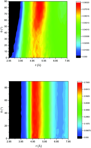
Insight into the structural properties of the liquid is obtained from the angular radial distribution function (ARDF) of benzene, i.e. the RDF plotted as a function of the angle between the Z axis of a central molecule and the surrounding molecules. In this case, the Z axis is defined as the axis pointing out of the benzene ring, perpendicular to the plane of a C–C bond, and as such an angle of 0° θ corresponds to benzene molecules parallel to each other and 90° θ benzenes perpendicular to each other. Fig. 1 gives this function for both the unconfined bulk and confined systems. The bulk benzene ARDF shows the preferential location for a neighbouring benzene to be sited is 5.55 Å at 90° θ. There is a slight preference for parallel benzene molecules at distances <4 Å. This structure is similar to that observed previously from the analysis of total neutron scattering data.29 The ARDF of confined benzene shows significant changes to the structure with there being no preference in orientation at the most probable distance of 5 Å, which is clear evidence that confining the liquid changes the structure, forcing the benzene molecules closer together and disrupting any order present in the bulk liquid.
 | ||
| Fig. 1 ARDF of bulk benzene (top) and benzene confined in flexible MCM-41 (bottom); colour scheme – black (no intensity) to blue (low intensity) to red (high intensity). | ||
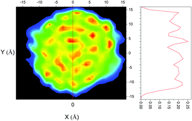
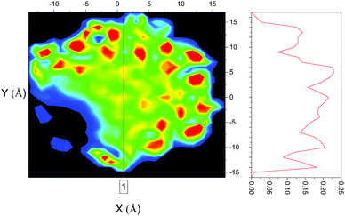
The confined liquid does, however, have significant structure, as is clearly shown in Fig. 2 which plots the simulated probability density of benzene inside the flexible MCM-41 pores demonstrating that, when confined, three concentric rings on average 4.8 Å apart are formed – approximately the diameter of benzene (5 Å30). When compared to the rigid model, Fig. 3, the flexible model shows the more realistic behaviour with the whole pore area filled. The rigid model of MCM-41 shows areas of low probability of finding a benzene where the rigid pore walls block the movement of benzene showing the significant limitations of this model.
Both methods (QENS and MD) agree that benzene diffuses more slowly when confined in MCM-41. Moreover, in both the unconfined and confined systems, the MD simulations are close to the QENS experiments. The very close match between the confined systems shows the use of the novel fully flexible framework is very well suited to simulations of this type, which provides confidence in the structural properties revealed by the simulations (Table 3).
| Temperature (K) | Jump distance (Å) | Residence time (ps) | Ds L1 m2 s−1 (×10−9) | |||
|---|---|---|---|---|---|---|
| Bulk | Confined | Bulk | Confined | Bulk | Confined | |
| 300 | 3.26 | 3.57 | 5.27 | 11.11 | 3.37 | 1.91 |
| 325 | 3.48 | 3.45 | 3.94 | 11.28 | 5.13 | 1.75 |
| 350 | 3.22 | 3.28 | 3.43 | 8.76 | 5.02 | 2.04 |
Turning now to a more detailed analysis of the QENS measurements, we find that the data are fit with a delta peak corresponding to the elastic peak convoluted with the resolution function, and two Lorentzians that describe the diffusive motions. The need for two Lorentzians strongly suggests that there are two types of motion present in the system. A full description of the QENS analysis is found in the ESI.† A more detailed examination of the diffusion data for the narrower Lorentzian motion (L1) indicates that both the confined and bulk benzene have similar jump distances suggesting that the same motion is taking place.
However, when confined in Pt/MCM-41, the residence time has more than doubled and the diffusion coefficient decreased suggesting that this motion is now substantially slower. The jump distance of, on average, 3.4 Å is the same as the distance moved by a hydrogen atom on the benzene ring as the ring rotates 90°, which may suggest that the jump motion observed is the movement of the benzene ring from parallel to perpendicular orientations, which in a tumbling motion would match the distance of the jumps. The elastic incoherent structure factor of both bulk benzene (Fig. S10, ESI†) and confined benzene (Fig. S17, ESI†) suggests that the motion is of a translational nature due to the sharp decay to values close to 0 therefore discounting a rotational motion. This translational motion corresponds to the second Lorentzian. Further evidence is found in the ARDF which shows a transition from parallel to perpendicular in the bulk liquid from distances of 3 to 5 Å. A previous QENS measurement of benzene in MCM-417 also found a jump diffusion motion with a residence time of 7.53 ps, a jump length of 3.14 Å and a diffusion coefficient of 2.18 × 10⁻⁹ m2 s−1 which is very similar to the result of the QENS experiment reported here.
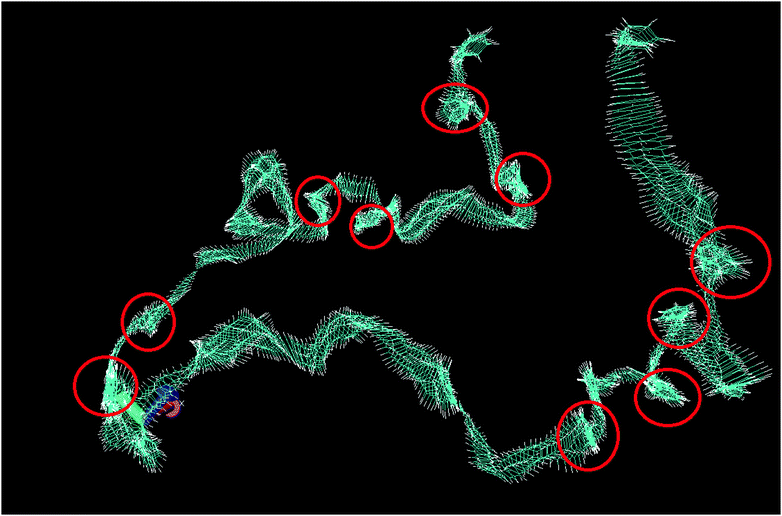
Fig. 4 shows the trajectory of a single molecule of bulk benzene at 300 K through 1 ns, with the trajectory smoothed by averaging over a period of 5 timesteps; every individual image of a benzene molecule in Fig. 4 shows its average position at 5 timesteps. This smoothing has been performed to remove some of the thermal vibrational motion in order for the overall motion of the benzene to be visualised more clearly. The figure reveals the two motions of benzene in agreement with the QENS analysis. There are long periods of translational motion corresponding to the second Lorentzian translational diffusion motion interspersed by other motions highlighted by the red circles in Fig. 4. The latter, which are jump diffusion modes are then assigned to the narrow Lorentzian motion. This motion is then hindered in the confined liquid.
 | ||
| Fig. 4 Total trajectory of benzene through 1 ns, showing the position of benzene at every timestep. Red circles are areas of motion that are not translational. | ||
Conclusions
The combined use of QENS experiments and MD simulations to study the dynamical behaviour of benzene inside Pt/MCM-41 has provided considerable insight into the dynamics underpinning an industrially relevant process inside the pores of a catalyst. We found that confining benzene inside the pores causes a decrease in the mobility as shown by the decrease of diffusion coefficient. Comparing a flexible and rigid MD model for the MCM-41 framework in studying the dynamics of the system demonstrates that the results from the fully flexible framework results in much better agreement with those obtained experimentally and leads to a more even distribution of confined molecules throughout the pore. The flexible pore also prevents parts of the pore becoming inaccessible as seen with the rigid model. However, all simulation results are within the same order of magnitude of the QENS experiments showing that combined QENS-MD studies are a valuable tool in quantifying the dynamics and studying the qualitative behaviour of a system; and our analysis of the dynamics using both QENS and simulations reveals an intriguing combination of unhindered translational and jump diffusion.The work presented here is a first step in the design of better catalysts. If it is accepted that the liquid diffusion inside the catalyst pores is critical in determining the rate of reaction1 then the quantification of the diffusion as presented here is essential. Our work also has more general consequences for the understanding of the structure and dynamics of confined liquids.
Conflicts of interest
There are no conflicts to declare.Acknowledgements
The authors acknowledge the use of the UCL Legion High Performance Computing Facility (Legion@UCL), and associated support services, in the completion of this work. UK Catalysis Hub is kindly thanked for resources and support provided via our membership of the UK Catalysis Hub Consortium and funded by EPSRC (grants EP/K014706/2, EP/K014668/1, EP/K014854/1, EP/K014714/1 and EP/M013219/1) as well as the EPSRC grant EP/N008995/1. We are grateful to Robert Bell for suppling the coordinates for his model of MCM 41. AJOM acknowledges the Ramsay Memorial Trust for provision of the Ramsay Fellowship. Experiments at the ISIS Pulsed Neutron and Muon Source were supported by a beamtime allocation from the Science and Technology Facilities Council (RB1610076).References
- T. G. A. Youngs, H. Manyar, D. T. Bowron, L. F. Gladden and C. Hardacre, Chem. Sci., 2013, 4, 3484–3489 RSC.
- M. Saeys, M.-F. Reyniers, M. Neurock and G. B. Marin, J. Phys. Chem. B, 2005, 109, 2064–2073 CrossRef CAS PubMed.
- A. J. O’Malley, S. F. Parker and C. R. A. Catlow, Chem. Commun., 2017, 53, 12164–12176 RSC.
- H. Jobic and D. N. Theodorou, Microporous Mesoporous Mater., 2007, 102, 21–50 CrossRef CAS.
- L. Bonneviot, F. Béland, C. Danumah, S. Giasson and S. Kaliaguine, Mesoporous Molecular Sieves, Elsevier Science, 1998 Search PubMed.
- C. Krause, F. Stallmach, D. Hönicke, S. Spange and J. Kärger, Adsorption, 2003, 9, 235–241 CrossRef CAS.
- A. Sahasrabudhe, S. Mitra, A. K. Tripathi, R. Mukhopadhyay and N. M. Gupta, J. Phys. Chem. B, 2002, 106, 10923–10929 CrossRef CAS.
- S. Mitra, V. S. Kamble, A. K. Tripathi, N. M. Gupta and R. Mukhopadhyay, Pramana, 2004, 63, 443–448 CrossRef CAS.
- B. Coasne and J. T. Fourkas, J. Phys. Chem. C, 2011, 115, 15471–15479 CrossRef CAS.
- J. H. Kim and S. H. Lee, Bull. Korean Chem. Soc., 2002, 23, 5–10 Search PubMed.
- Y. Jing, L. Wei, Y. Wang and Y. Yu, Chem. Eng. J., 2013, 220, 264–275 CrossRef CAS.
- C. Schumacher, J. Gonzalez, P. A. Wright and N. A. Seaton, J. Phys. Chem. B, 2006, 110, 319–333 CrossRef CAS PubMed.
- C. Herdes, C. A. Ferreiro-Rangel and T. Düren, Langmuir, 2011, 27, 6738–6743 CrossRef CAS PubMed.
- T. Nanok, P. A. Bopp and J. Limtrakul, Construction, 2005, 805–813 CAS.
- A. J. O’Malley and C. R. a Catlow, Phys. Chem. Chem. Phys., 2013, 15, 19024–19030 RSC.
- D. Holden, K. E. Jelfs, A. Trewin, D. J. Willock, M. Haranczyk and A. I. Cooper, J. Phys. Chem. C, 2014, 118, 12734–12743 CrossRef CAS.
- W. Smith, C. W. Yong and P. M. Rodger, Mol. Simul., 2002, 28, 37–41 CrossRef.
- T. G. A. Youngs, J. Comput. Chem., 2010, 31, 639–648 CAS.
- L. Martínez, R. Andrade, E. G. Birgin and J. M. Martínez, J. Comput. Chem., 2009, 30, 2157–2164 CrossRef PubMed.
- R. G. Bell, Proceedings of the 12th International Zeolite Conference, 1999, 839–845.
- Z. Du and N. H. D. Leeuw, Surf. Sci., 2004, 554, 193–210 CrossRef CAS.
- M. J. Sanders, M. Leslie and C. R. A. Catlow, J. Chem. Soc., Chem. Commun., 1984, 4, 1271 RSC.
- K. P. Schröder, J. Sauer, M. Leslie, C. Richard, A. Catlow and J. M. Thomas, Chem. Phys. Lett., 1992, 188, 320–325 CrossRef.
- G. Sastre, C. R. A. Catlow and A. Corma, J. Phys. Chem. B, 1999, 103, 5187–5196 CrossRef CAS.
- L. Whitmore, B. Slater and C. R. A. Catlow, Phys. Chem. Chem. Phys., 2000, 2, 5354–5356 RSC.
- I. Yeh and G. Hummer, J. Phys. Chem. B., 2004, 108, 15873–15879 CrossRef CAS.
- G. Sastre, N. Raj, C. R. A. Catlow, R. Roque-Malherbe and A. Corma, J. Phys. Chem. B, 1998, 102, 3198–3209 CrossRef CAS.
- F. Jousse, S. M. Auerbach and D. P. Vercauteren, J. Phys. Chem. B, 2000, 104, 2360–2370 CrossRef CAS.
- M. Falkowska, D. T. Bowron, H. G. Manyar, C. Hardacre and T. G. A. Youngs, ChemPhysChem, 2016, 17, 2043–2055 CrossRef CAS PubMed.
- C. Alba-Simionesco, G. Dosseh, E. Dumont, B. Frick, B. Geil, D. Morineau, V. Teboul and Y. Xia, Eur. Phys. J. E: Soft Matter Biol. Phys., 2003, 12, 19–28 CrossRef CAS PubMed.
Footnote |
| † Electronic supplementary information (ESI) available. See DOI: 10.1039/d0cp01196g |
| This journal is © the Owner Societies 2020 |


