
 Open Access Article
 This Open Access Article is licensed under a Creative Commons Attribution-Non Commercial 3.0 Unported Licence
A donor-chromophore-catalyst assembly for solar CO2 reduction†
Degao
Wang‡
a,
Ying
Wang‡
a,
Matthew D.
Brady
a,
Matthew V.
Sheridan
 a,
Benjamin D.
Sherman
b,
Byron H.
Farnum
a,
Yanming
Liu
a,
Seth L.
Marquard
a,
Gerald J.
Meyer
a,
Christopher J.
Dares
c and
Thomas J.
Meyer
*a
a,
Benjamin D.
Sherman
b,
Byron H.
Farnum
a,
Yanming
Liu
a,
Seth L.
Marquard
a,
Gerald J.
Meyer
a,
Christopher J.
Dares
c and
Thomas J.
Meyer
*a
aDepartment of Chemistry, University of North Carolina Chapel Hill, Chapel Hill, North Carolina 27599, USA. E-mail: tjmeyer@unc.edu
bDepartment of Chemistry, Texas Christian University, Fort Worth, Texas 76129, USA
cDepartment of Chemistry and Biochemistry, Florida International University, 11200 SW Eighth Street, Miami, Florida 33199, USA
First published on 14th March 2019
Abstract
We describe here the preparation and characterization of a photocathode assembly for CO2 reduction to CO in 0.1 M LiClO4 acetonitrile. The assembly was formed on 1.0 μm thick mesoporous films of NiO using a layer-by-layer procedure based on Zr(IV)–phosphonate bridging units. The structure of the Zr(IV) bridged assembly, abbreviated as NiO|-DA-RuCP22+-Re(I), where DA is the dianiline-based electron donor (N,N,N′,N′-((CH2)3PO3H2)4-4,4′-dianiline), RuCP2+ is the light absorber [Ru((4,4′-(PO3H2CH2)2-2,2′-bipyridine)(2,2′-bipyridine))2]2+, and Re(I) is the CO2 reduction catalyst, ReI((4,4′-PO3H2CH2)2-2,2′-bipyridine)(CO)3Cl. Visible light excitation of the assembly in CO2 saturated solution resulted in CO2 reduction to CO. A steady-state photocurrent density of 65 μA cm−2 was achieved under one sun illumination and an IPCE value of 1.9% was obtained with 450 nm illumination. The importance of the DA aniline donor in the assembly as an initial site for reduction of the RuCP2+ excited state was demonstrated by an 8 times higher photocurrent generated with DA present in the surface film compared to a control without DA. Nanosecond transient absorption measurements showed that the expected reduced one-electron intermediate, RuCP+, was formed on a sub-nanosecond time scale with back electron transfer to the electrode on the microsecond timescale which competes with forward electron transfer to the Re(I) catalyst at t1/2 = 2.6 μs (kET = 2.7 × 10⁵ s−1).
Introduction
In natural photosynthesis, conversion of sunlight and CO2 into chemical fuels integrates light absorption and catalysis.1–7 In Dye Sensitized Photoelectrosynthesis Cells (DSPECs) molecular assemblies are integrated with light absorbers and catalysts on electrode surfaces for water splitting or reduction of CO2.8–12 Significant advances have been made in the last ten years developing high efficiency photoanodes for water oxidation and proton reduction, while progress on the development of high photocurrent efficiency photocathodes for CO2 reduction still remains challenging.13–21Due to its chemical significance, many innovative approaches have been developed to advance the photoreduction of CO2.22–33 These studies reflect considerable effort to use abundant minerals as catalysts and light absorbers alongside the long standing issue of developing more efficient components as a whole. Several novel strategies have been utilized for CO2 fixation including biosynthesis,27 the use of spongy materials,28 and utilization of metal–organic-frameworks.31
The approach to CO2 reduction using a DSPEC in this work makes use of molecular chromophore and catalyst species adsorbed on a NiO semiconductor electrode. Using this strategy, Ishitani and co-workers have made significant progress in the area of CO2 reduction devices,33,34 and related approaches between these and water splitting photoanodes such as the use of tandem cells for unbiased DSPEC operation and development of more effective photoelectrode materials have been advanced in recent years.35,36
The key reactions involved in the light-driven CO2 reduction process for this device are summarized in eqn (1)–(3). Excitation of the chromophore (Chrom) by sunlight in eqn (1), results in an excited state which, following excitation and injection, leads to formation of a hole in the semiconductor NiO(h+), and electron transfer to the catalyst, Cat, eqn (2). The latter begins the process of catalyst activation of a cycle for CO2 reduction, eqn (3). The latter reaction is in competition with back electron transfer from the electrode in this device, eqn (4). The final step in the process, to complete the circuit, is conduction of the injected hole to an anode (here, a Pt wire for dark water oxidation), eqn (5).
Injection
| NiO|Chrom-Cat + hν → NiO(h+)|Chrom(e−)-Cat | (1) |
Catalyst activation
| NiO(h+)|Chrom(e−)-Cat → NiO(h+)|Chrom-Cat(e−) | (2) |
CO2 reduction step
| NiO(h+)|Chrom-Cat(e−) + CO2 → NiO(h+)|Chrom-[Cat-CO2]− | (3) |
Back electron transfer
| NiO(h+)|Chrom-Cat(e−) → NiO|Chrom-Cat | (4) |
Anode oxidation
| NiO(h+)|Chrom-[Cat-CO2]− + anode → NiO|Chrom-Cat(e−) + anode(h+) | (5) |
However, the collective results of an extensive literature on NiO based photocathodes have not been promising for practical applications thus far.9,37–45 Transient optical experiments have shown that, following excited state injection on NiO, rapid back electron transfer dominates (eqn (4)), resulting in low steady state concentrations of semiconductor holes and low photocurrent efficiencies in the multi-electron reduction of CO2 to CO, eqn (6).
| 2H+ + CO2 + 2e− → H2O + CO | (6) |
In natural photosynthesis, photon excitation and electron transfer catalysis are linked through an assembly of redox active groups that provide a free energy gradient for directed electron and hole transfer. This natural assembly supports electron transfer over long distances which inhibit back electron transfer because of the exponential dependence of outer-sphere electron transfer on distance.46–48 The strategy has not been generally utilized, in part, because of the complexity of adding additional components to the device and a lack of understanding various pathways for electron transfer.
We report here a layer-by-layer preparation and the resulting properties of a chromophore-catalyst assembly for CO2 reduction to CO. The approach also provides spatial control of electron transfer by using an electron-donating dianiline mediator (‘Donor’). The assembly was based on a previous report of assembly formation by layer-by-layer synthesis that gave assemblies integrated functional units for light absorption, electron transfer quenching, and catalysis in single molecule arrays.49–54 Here, the same procedure was utilized to prepare a NiO|-donor-chromophore-catalyst molecular assembly for CO2 reduction in a DSPEC. The complete surface assembly produced sustained photocurrents (>45 μA cm−2 over 20 minutes), and produced CO with a faradaic efficiency of 85% under an applied bias of −0.54 V vs. NHE.
Experimental
Materials
Dry acetonitrile was purchased from Sigma-Aldrich and used as received. All other reagents were purchased from Sigma-Aldrich without further purification. N,N,N′,N′-((CH2)3PO3H2)4,4′-dianiline (DA) was prepared according to the reported literature.55 The [Ru(4,4′-(PO3H2CH2)2-2,2′-bipyridine)2(2,2′-bipyridine)2]2+ (RuCP22+) chromophore was made according to previously published procedures.56 The Re complex was prepared following the protocol reported by Schreier et al.20Film preparation
![[thin space (1/6-em)]](https://www.rsc.org/images/entities/char_2009.gif) 000) into 30% ITO ethanol solution. After stirring for 2 days, the nanoITO solution was deposited on FTO (TEC 15, Hartford Glass, Hartford City, IN) using one layer of Scotch tape as a spacer. The slides were annealed in box oven for 1 hour at 450 °C. The film thickness was estimated as ca. 2.3 μm by profilometry.
000) into 30% ITO ethanol solution. After stirring for 2 days, the nanoITO solution was deposited on FTO (TEC 15, Hartford Glass, Hartford City, IN) using one layer of Scotch tape as a spacer. The slides were annealed in box oven for 1 hour at 450 °C. The film thickness was estimated as ca. 2.3 μm by profilometry.
Surface assembly formation
NiO films were first immersed in 0.1 M HClO4 aqueous solutions containing 2 mM of the aromatic donor N,N,N′,N′-((CH2)3PO3H2)-4,4′-dianiline (DA) for 12 hours. After copious rinsing with 0.1 M HClO4 water, they were dried under N2 and placed in a 5 mM aqueous solution of zirconyl chloride (ZrOCl2) with 0.1 M HClO4 for 2 hours. Following a drying cycle under N2, the thin films were further immersed in a 0.1 mM solution of the chromophore [Ru(4,4′-(PO3H2CH2)2-2,2′-bipyridine)2(2,2′-bipyridine)2]2+ (RuCP22+) for 12 hours. Surface coordination was followed by rinsing and drying steps and then addition of a second layer of Zr(IV). In the final step, the NiO|-DA-Zr(IV)-RuCP22+-Zr(IV) electrodes were soaked in methanol solutions containing the catalyst, ReI((4,4′-PO3H2CH2)2-2,2′-bipyridine)(CO)3Cl, at 2 mM for 24 hours to give the assembly, NiO|-DA-RuCP22+-Re(I).The control electrode NiO|-RuCP22+-Re(I) was fabricated by immersing NiO films in a 0.1 mM solution of the chromophore [Ru(4,4′-(PO3H2CH2)2-2,2′-bipyridine)2(2,2′-bipyridine)2]2+ (RuCP22+) for 12 hours. Surface coordination was followed by rinsing and drying steps and then the addition of a layer of Zr(IV) which was formed by soaking in a 5 mM aqueous solution of ZrOCl2 in 0.1 M HClO4 for 2 hours. In the next step, the NiO|-RuCP22+-Zr(IV) electrodes were soaked in methanol solution containing the catalyst, Re(I)((4,4′-PO3H2CH2)2-2,2′-bipyridine)(CO)3Cl, at 2 mM for 24 hours to give the assembly, NiO|-RuCP22+-Re(I). The electrode nanoITO|-RuCP22+-Re(I) was made using an identical procedure but with nanoITO replacing the NiO film.
Instrumentation
UV-visible absorbance measurements were performed using an Agilent Technologies Cary 8454 UV-visible spectrometer.Scanning electron microscope (SEM) images were obtained on a FEI Helios 600 Nanolab Dual Beam System focused ion beam (FIB) equipped with an Oxford Instruments, INCA PentaFET-x3 X-ray detector with the electron beam set to 2 keV and a beam current of 0.69 nA.
XPS spectra were acquired by using a Kratos Axis Ultra DLD X-ray photoelectron spectrometer with a base pressure of 6 × 10⁻⁹ Torr, a monochromatic Al Kα X-ray source, and an analyzer pass energy of either 80 eV or 20 eV for survey and high resolution scans respectively.
X-ray diffraction were used to characterize the prepared NiO films. A Rigaku SmartLab was utilized which consisted of an X-ray source (3 kW Cu tube) and the detector – a 0D scintillation detector.
Gas chromatography
At the end of a photoelectrochemical experiment, 0.6 mL of a gaseous sample was taken out of the sealed headspace by a gas tight syringe (Vici) and injected into a gas chromatograph (Varian 450-GC). A temperature gradient program was used starting at 40 °C which was ramped to 220 °C at 20 °C min−1. The calibration curves for H2 and CO were obtained by using certified standard gas samples obtained from Sigma-Aldrich (SCOTTY gas standards). The column used for GC here was Shin Carbon.Photoelectrochemical measurements
Electrochemical and photoelectrochemical measurements were performed by using a CH Instruments 760E bipotentiostat. The white light illumination (400 nm cut-off, 100 mW cm−2) was provided by a THORLABS HPLS 30-04 light source. Incident photon to current efficiency (IPCE) measurements were performed with a 75 W xenon lamp (Oriel) and Oriel Cornerstone 260 monochromator. Photocurrent data were taken at 5 nm increments and the light intensity at each wavelength was recorded by using a UDT S370 optometer coupled to a UDT 260 detector. A CH Instruments 660D potentiostat was used to record the photocurrent transients and a bias of −0.54 V vs. NHE was used during collection of the IPCE data.Spectroelectrochemical measurements
Spectroelectrochemical measurements were used to evaluate surface-bound redox potentials and spectral features for transient absorption kinetic analysis. The spectra were modeled from a linear combination of the ground state spectrum and the fully oxidized DA or fully reduced ‘RuCP2+’ and ‘Re(0)’ intermediates to determine mole fractions of each species at the applied potentials. The potential where equal amounts of the two redox species (neutral and reduced or oxidized) were present was taken as the formal reduction potential. Delta extinction coefficient spectra (Δε) were calculated with the assumption that the solution extinction coefficients for all the complexes remain the same on the surface.Steady-state photoluminescence
Steady spectra were obtained with a HORIBA Fluorolog spectrophotometer equipped with a 450 W Xe arc lamp for the excitation source. PL spectra were obtained at room temperature with PL detected at a front facing orientation when it contacted a slide. The excitation wavelength for photoluminescence was 450 nm.Transient absorption
Nanosecond transient absorption measurements were acquired on a setup described previously.57 Briefly, a Q-switched, pulsed Nd:YAG laser (Quantel U.S.A. (BigSky) Brilliant B 5–6 ns full width at half-maximum (fwhm), 1 Hz, ∼10 mm in diameter) doubled to 532 nm was passed through an OPO and tuned to 488 nm. The laser irradiance at the sample was attenuated to 4.5 mJ per pulse. A 150 W xenon arc probe lamp was pulsed at 1 Hz with 70 V during the experiment. Signal detection was achieved using a monochromator (SPEX 1702/04) optically coupled to an R928 photomultiplier tube (Hamamatsu) at a right angle to the excitation laser. Transient data were acquired with a computer-interfaced digital oscilloscope (LeCroy 9450, Dual 330 MHz) with an overall instrument response time of ∼20 ns. 30 laser pulses were acquired and averaged at each wavelength over the 370–800 nm range. Intervals of 10 nm were used for wavelengths between 370 and 600 nm and intervals of 20 nm were used between 600 and 800 nm.Results and discussion
Synthesis and characterization
Scheme 1 illustrates the components used for the preparation of the surface assembly. Coordination to the surface and assembly formation were based on phosphonate–Zr(IV) bridges on the surfaces of mesoporous 1.0 μm thick films of NiO composed of 15–20 nm diameter NiO particles.58,59 SEM and XRD characterization of NiO films are shown in Fig. S1 and S2.† Details on the preparation of the NiO films is provided in the experimental section. The final structure, with the Zr(IV) bridging groups, is shown in Scheme 1, with a redox potential diagram shown in Fig. 1.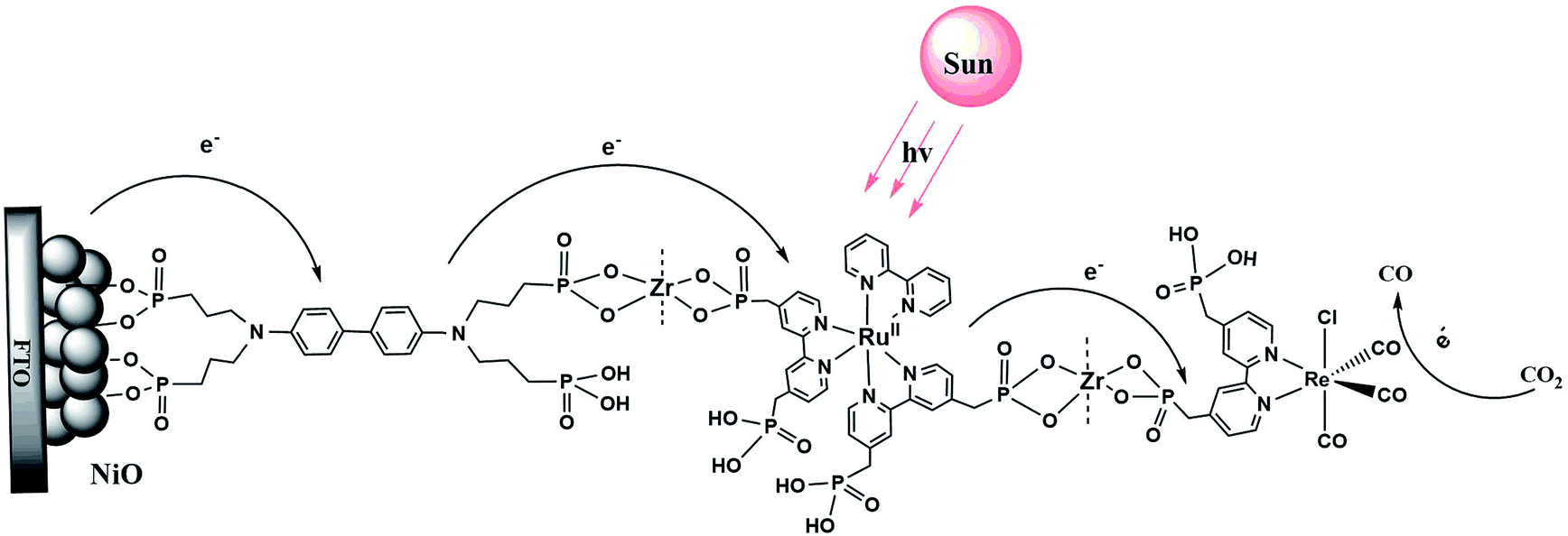 | ||
| Scheme 1 Structure of the assembly NiO|-DA-RuCP22+-Re(I) on a mesoporous NiO electrode. | ||
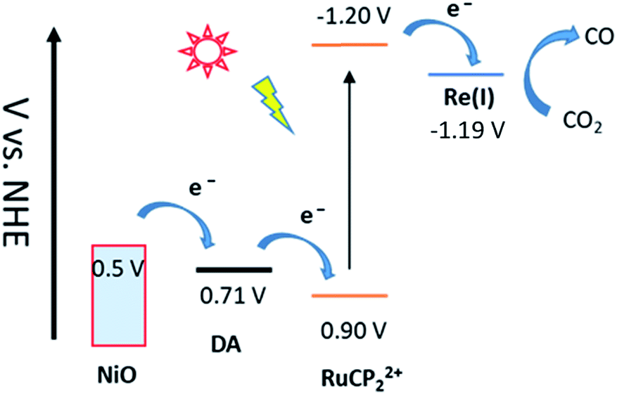 | ||
| Fig. 1 Redox potential diagram for the assembly, NiO|-DA-RuCP22+-Re(I), illustrating excitation and stepwise electron transfer following excitation of the RuCP22+ chromophore. | ||
UV-visible absorption measurements were used to monitor assembly formation. Typical data are illustrated in Fig. 2 for NiO|-DA, NiO|-DA-RuCP22+, and NiO|-DA-RuCP22+-Re(I). The spectrum of the assembly NiO|-DA-RuCP22+ includes a metal-to-ligand charge-transfer (MLCT) absorption maximum at 460 nm which corresponds to a region expected for the Ru(II) chromophore MLCT. In the final assembly, NiO|-DA-RuCP22+-Re(I), the absorption spectrum includes an additional feature, the CO2 catalyst, with a MLCT absorption at 350–450 nm. The spectrum of the Re(I) catalyst in methanol solution is shown in Fig. S3† for comparison. Based on the relation Γ = A/(ε 1000), the surface coverage of the chromophore RuCP22+ was Γ = 2 × 10⁻⁸ mol cm−2 at ε(460 nm) = 1.39 × 10⁴ M−1 cm−1 for the RuCP2+ chromophore.
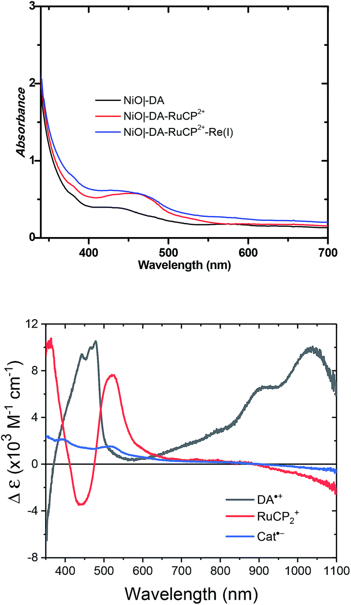 | ||
| Fig. 2 UV-visible absorption spectra of neutral molecular assemblies on NiO electrodes measured in air (top), and the corresponding spectra for each oxidized (DA) or reduced (RuCP2 or Cat) species obtained by spectroelectrochemistry (bottom). | ||
To verify the presence of the catalyst, an XPS spectrum that included Re-based absorptions for 4f5/2 at 42.8 eV and for 4f7/2 at 40.7 eV, was obtained with peak energies consistent with literature values, as shown Fig. S4.† According to the elemental analysis of the XPS measurements (data shown in the bottom of Fig. S4†), the ratio of Re:Ru in the NiO|-DA-RuCP22+-Re assembly was approximately 1:1, consistent with a 1:1 ratio in the final assembly and full surface loading.
| a On nanoITO electrodes, V vs. NHE at room temperature in acetonitrile 0.1 M in LiClO4 measured using a Ag+/Ag quasi-reference electrode referenced internally to the ferrocenium/ferrocene couple with Fc+/Fc taken as 0.62 V vs. NHE. | ||||
|---|---|---|---|---|
| Species | DA+/0 | RuCP22+/+ | RuCP22+*/+ | Re(I) |
| Couple | +˙/0 | 2+/+ | 2+*/+ | 1+/0˙ |
| E′ (V) | 0.71 | −1.20 | 0.90 | −1.19 |
For electrochemical measurements, the same preparation procedure was used as described for the assemblies on NiO surfaces, however, an indium doped tin oxide (nanoITO) substrate was used instead of NiO. Redox properties of the assemblies nanoITO|-DA, nanoITO|-RuCP22+, and nanoITO|-Re(I), were investigated by spectro-electrochemistry on mesoporous nanoITO films in 0.1 M LiClO4 acetonitile. From the data in Fig. S5 and S6,† a quasi-reversible, reduction appears at 0.71 V for the DA+˙/0 couple, at −1.19 V for the -ReI/0˙ couple, and at −1.20 V and for the -RuCP22+/+ couple vs. NHE. The values of the re-oxide couples are summarized in Table 1. The individual spectra are highlighted at the bottom of Fig. 2.
Photocurrent studies
The photocurrent responses of NiO|-RuCP22+-Re(I) and NiO|-DA-RuCP22+-Re(I) electrodes were studied using a standard three-electrode photoelectrochemical cell with 1 sun illumination (100 mW cm−2, 400 nm cutoff filter) in CO2 saturated 0.1 M LiClO4 acetonitrile solution. The working electrodes were NiO|-RuCP22+-Re(I) or NiO|-DA-RuCP22+-Re(I) with a platinum wire as the counter electrode and a Ag/Ag+ quasi-reference electrode. After three 10 s light on/off cycles, the photocurrent response for NiO|-DA-RuCP22+-Re(I) was ∼65 μA cm−2 at the end of each cycle. This photocurrent response was nearly 8 times larger than that measured for an assembly without the DA electron transfer mediator, NiO|-RuCP22+-Re(I), as shown in Fig. 3a. The enhanced photocurrent density with the dianiline donor arises from intra-assembly electron transfer initially from the DA donor to the MLCT excited state of RuCP22+*, discussed below. Results of a long term photolysis experiment using NiO|-DA-RuCP22+-Re(I) conducted over a 20 min period (Fig. 3b) showed photocurrents for the assembly NiO|-DA-RuCP22+-Re(I) decreasing by ca. 40% over this time period.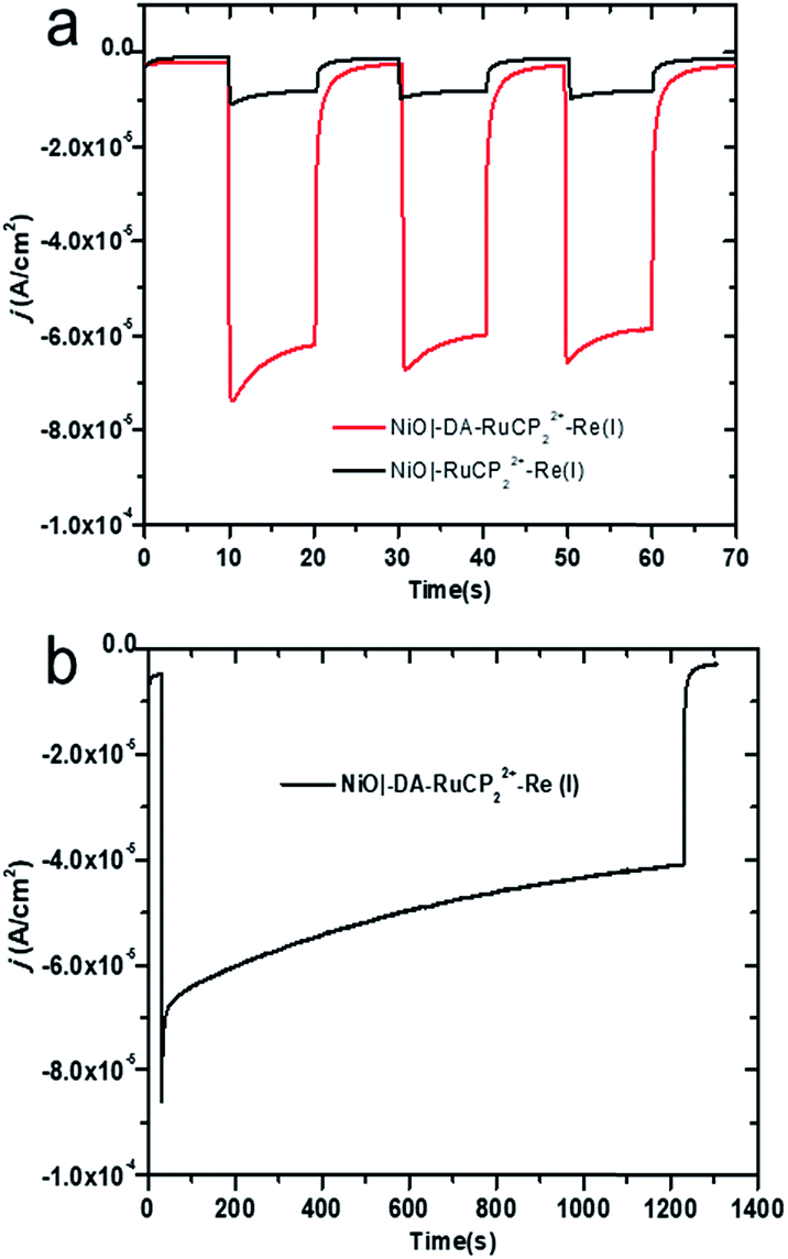 | ||
| Fig. 3 (a) Photocurrent density versus time (j–t) plots for NiO assemblies with three 10 s dark–light (one sun illumination) cycles with an applied bias of −0.54 V vs. NHE in 0.1 M in LiClO4 acetonitrile under 1 atm CO2. (b) Photocurrent response of NiO|-DA-RuCP22+-Re(I), over a 20 min period under the same conditions as described for (a). | ||
To test for the effect of applied bias, current densities were measured with the bias voltage was scanned from −0.95 to 0.4 V vs. NHE under light and dark conditions, Fig. S8.† More negative applied voltages increased the photocurrent density up to the background catalytic wave starting at ca. −0.8 V. As a note, there was no evidence for background catalytic behavior toward CO2 reduction by NiO|-DA-RuCP22+-Re(I) until an applied bias of −0.8 V vs. NHE was reached under dark conditions. When illuminated, the NiO|-DA-RuCP22+-Re(I) photocathode maintained in cathodic current up to a bias of −0.1 V vs. NHE, 0.7 V more positive than the electrocatalytic onset potential. For comparison, the same experiments were carried out with the assembly NiO|-RuCP22+-Re(I) under dark and light conditions in CO2 saturated 0.1 M NaClO4 acetonitrile solution as shown in Fig. S9.† While the surface still showed a photocathodic response, the photocurrent density was substantially lower as compared to the full assembly containing the DA unit (Fig. S8†), consistent with Fig. 3a. As noted above, the photocurrent density obtained at the DA assembly represents significant improvement over the electrode without the electron mediator, NiO|-RuCP22+-Re(I). Enhancements in the photocurrent can be largely attributed to better local charge separation and reduced back electron transfer with the added dianiline donor.
Incident photon-to-current efficiency (IPCE) measurements as a function of excitation wavelength are shown in Fig. S10.† The IPCE value for the assembly NiO|-DA-RuCP22+-Re(I) was obtained at an applied bias of −0.54 V versus NHE in CO2 saturated 0.1 M NaClO4 acetonitrile solution. The IPCE profiles overlap with the MLCT absorption profile for the chromophore, as expected for dye-sensitized CO2 reduction. From Fig. S10,† the IPCE value for the assembly, NiO|-DA-RuCP22+-Re(I), was 1.9% at the absorption maximum for the RuCP22+ chromophore at 450 nm.
Product analysis
Gas chromatography (GC) was used to estimate faradaic efficiencies for CO2 reduction to CO for both NiO|-RuCP22+-Re(I) and NiO|-DA-RuCP22+-Re(I). GC analysis revealed that CO was the major product for both assemblies as shown in Fig. 4. From the data in Fig. 4, the appearance of CO for NiO|-DA-RuCP22+-Re(I), as a product of CO2 reduction, is considerably enhanced compared to NiO|-RuCP22+-Re(I). For the latter, the ratio of H2 to CO was 1:3 and for the former (assembly with DA), the ratio of H2 to CO was 1:8.
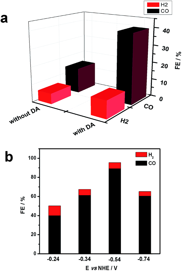 | ||
| Fig. 4 (a) Analysis of CO2 reduction products following excitation of NiO|-RuCP22+-Re(I) with 100 mW cm−2 white light source with a bias of −0.24 V vs. NHE in CO2 saturated 0.1 M LiClO4 acetonitrile. (b) Photoelectrochemical CO2 reduction products for same materials as a function of applied bias. | ||
The product distribution for NiO|-DA-RuCP22+-Re(I) was also investigated as a function of applied potential. At −0.54 V NHE, the ratio of CO to H2 increased nearly to 30:1 with concurrent increase in the faradaic efficiency for CO production to 85% with 3% H2 production. The turnover number (TON) for CO2 reduction from this experiment was calculated by comparing it to the number of adsorbed catalyst species and a TON of 22 was obtained with a bias of −0.54 V vs. NHE during 20 min measurements. By further increasing or decreasing the bias from −0.54 V, CO production was decreased.
Transient absorption
Interfacial, light-induced electron transfer dynamics were investigated by nanosecond transient absorption measurements on NiO|-DA-RuCP22+-Re(I) and NiO|-DA-RuCP22+. Samples were excited with pulsed 488 nm excitation (4.5 mJ per pulse) in argon-saturated 0.1 M LiClO4 acetonitrile solutions with an applied bias of −0.8 V vs. NHE. As shown in Fig. 5, transient absorption difference spectra measured after pulsed laser excitation revealed the prompt appearance of a band near 520 nm and an absorption edge that increased into the UV region.| NiO|-DA-RuCP22+* → NiO|-DA˙+-RuCP2+ | (7) |
| NiO|-DA˙+-RuCP2+ → NiO(h+)|-DA˙+-RuCP2+ | (8) |
| NiO(h+)|-DA-RuCP2+ → NiO|-DA-RuCP22+ | (9) |
| NiO|-DA-RuCP22+ + hν → NiO(h+)|-DA-RuCP2+ | (10) |
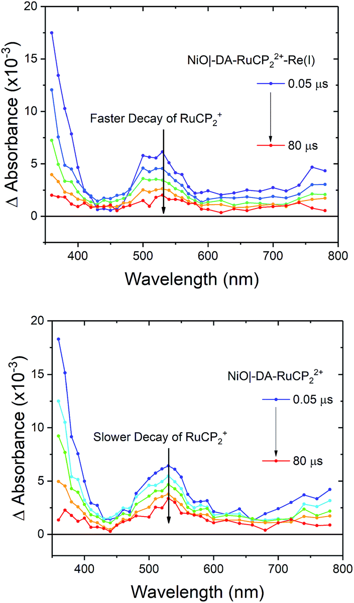 | ||
| Fig. 5 Nanosecond transient absorption difference spectra measured after pulsed 488 nm light excitation of NiO|-DA-RuCP22+-Re(I) (top) and NiO|-DA-RuCP22+ (bottom) in 0.1 M LiClO4 acetonitrile with −0.8 V vs. NHE applied potential under argon. | ||
For NiO|-DA-RuCP22+, excitation of the chromophore results in rapid (k > 108 s−1) intra-assembly quenching to give NiO|-DA˙+-RuCP2+, eqn (7), and, subsequent electron transfer to NiO(h+)|-DA-RuCP2+ (eqn (8)) after hole injection into NiO. The overall conversion to the final surface-assembly-based redox state is summarized in eqn (8), with back electron transfer a competing reaction, eqn (9). The initial electron transfer quenching by the dianiline, eqn (7), is favored by 0.19 V, and is not observed experimentally. Based on these results, and the 20 ns instrument response time, the rate constants for both the electron transfer from DA to RuCP22+* and from NiO to DA˙+ are assumed to be >108 s−1.
As shown by the data in Fig. 6, extension of the transient absorption measurements to NiO|-DA-RuCP22+-Re(I) gave comparable results. Analysis of time-dependent data at 530 nm showed that the kinetics of back electron transfer were non-exponential for both assemblies. The kinetics were characterized by the half time for the distribution, t1/2, the time at which the signal has decreased to half of its original amplitude. For the traces shown in Fig. 6, with the Re(I) catalyst, NiO(h+)|-DA-RuCP2+-Re(I), t1/2 was ∼2.0 μs. For NiO(h+)|-DA-RuCP2+, t1/2 was 8.5 μs. It is notable that the lifetime for the NiO(h+)|-DA-RuCP2+-Re(I) precursor decreased by a factor of ca. 4 compared to NiO(h+)|-DA-RuCP2+. This is consistent with electron transfer from RuCP2+ to Re(I), eqn (11).
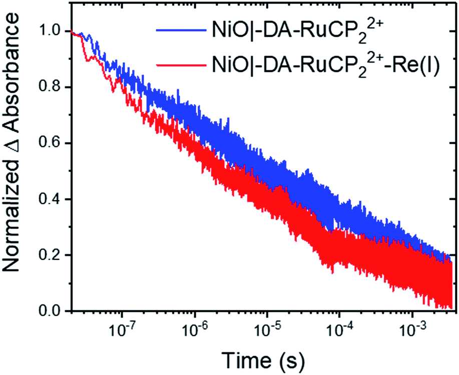 | ||
| Fig. 6 Normalized transient absorption changes measured at 530 nm after pulsed 488 nm excitation of NiO|-DA-RuCP22+ (blue) and NiO|-DA-RuCP22+-Re(I) (red) at −0.8 V vs. NHE in argon-saturated 0.1 M LiClO4 acetonitrile solution. | ||
Next, to calculate the kinetic rate constant for electron transfer in eqn (11), the difference in the loss of RuCP+ signal in the catalyst assembly can be attributed to either back electron transfer to NiO(h+) or electron transfer to the catalyst. Assuming the rate of back electron transfer is unchanged in the catalyst assembly, the equation for the rate constant is k(eqn (11)) = ln2(1/t1/2,A + 1/t1/2,B); where t1/2,A and t1/2,A are the two t1/2 obtained thus far. The calculated rate constant for eqn (11), k(eqn (11)) or kET, is therefore 3.7 × 10⁵ s−1 (t1/2,eqn (11) = 2.6 μs). In comparable Zr(IV) assemblies for light-driven water oxidation, hole transfer occurs with a half-life of 170 ps or 0.00017 μs (kET = 5.9 × 10⁹ s−1).60 The order of magnitude more sluggish electron transfer behaviour for transfer to the Re(I) catalyst is attributable to the 0.01 eV driving force for the reaction in eqn (11).
| NiO|-DA-RuCP2+-Re(I) → NiO|-DA-RuCP22+-Re(0) | (11) |
Mechanism
Insight into the mechanism for CO2 reduction to CO from the transient absorption experiments is limited by back electron transfer to the electrode. On the timescale of the nanosecond experiments, there is significant kinetic competition between back electron transfer and the rate of activation of the Re(I) catalyst without additional insight into the mechanism of CO2 reduction.There is an extensive mechanistic background in this area based on previous studies of Re(I) catalyst analogs in solution and as a component in assemblies with Ru(II) polypyridyl complexes.61–63Eqn (12) and (13) summarize the initial mechanistic steps. In the overall mechanism, the catalytic cycle is initiated by visible light absorption by the MLCT chromophore, -RuCP22+-, to give the MLCT excited state, -RuCP22+*-. Formation of the excited state is followed by its reduction by electron transfer from -DA- and electron transfer from the electrode to DA to give -RuCP2+- and NiO(h+). As shown in eqn (13), further electron transfer from the reduced chromophore occurs to the catalyst on the sub-ms timescale.
| NiO|-DA-RuCP2+-Re(I) + hν → NiO(h+)|-DA-RuCP2+-Re(I) | (12) |
| NiO(h+)|-DA-RuCP2+-Re(I)→NiO|-DA-RuCP22+-Re(0) | (13) |
Conclusions
We have successfully demonstrated here the synthesis, characterization, and properties of a surface-bound assembly for CO2 reduction to CO on the surface of mesoporous NiO electrodes. Formation of the electrode followed from a stepwise assembly synthesis based on phosphonate–Zr(IV) bridged structures to give the electrode, NiO|-DA-RuCP22+-Re(I). Compared to the assembly, NiO|-RuCP22+-Re(I), addition of the -DA- aniline donor was found to accelerate the catalytic effect by a factor of 8 by initial reduction of the MLCT excited state, -RuCP22+*, by the dianiline electron-donating mediator. With 1 sun illumination, photocurrents of up to 65 μA cm−2 were obtained for NiO|-DA-RuCP22+-Re(I) for CO2 reduction to CO under an atmosphere of CO2 in acetonitrile as the solvent.Nanosecond transient absorption measurements have been used to show that, in the assembly, initial excitation of the chromophore is followed by rapid, electron transfer to gives intermediate, NiO(h+)|-DA-RuCP2+-Re(I). This state undergoes back electron transfer on timescales shorter than a millisecond. Although not directly observed in the transient experiments, with an applied bias, reduction of the catalyst appears to be followed by a sequence of reactions that activate the catalyst toward CO2 reduction. Collectively the data show that a layer-by-layer synthetic approach can be utilized to spatially organize electron donors, catalysts, and chromophores on NiO surfaces for applications in solar fuel production.
Conflicts of interest
There are no conflicts to declare.Acknowledgements
This research was primarily supported by the UNC EFRC: Center for Solar Fuels, an Energy Frontier Research Center funded by the U.S. Department of Energy, Office of Science, Office of Basic Energy Sciences, under Award No. DE-SC0001011, GC and transient absorption experiments (Y. W., M. D. B., S. L. M.). Photoelectrochemical CO2 reduction was provided by D. W., supported by the U.S. Department of Energy (DOE), Nuclear Energy University Program award, under Contract DE-NE0008539. This work made use of instrumentation at the Chapel Hill Analytical and Nanofabrication Laboratory (CHANL), a member of the North Carolina Research Triangle Nanotechnology Network (RTNN), which is supported by the National Science Foundation (Grant ECCS-1542015) as part of the National Nanotechnology Coordinated Infrastructure (NNCI).References
- J. Barber, Chem. Soc. Rev., 2009, 38, 185–196 RSC.
- N. S. Lewis and D. G. Nocera, Proc. Natl. Acad. Sci. U. S. A., 2006, 103, 15729 CrossRef CAS PubMed.
- D. A. LaVan and J. N. Cha, Proc. Natl. Acad. Sci. U. S. A., 2006, 103, 5251 CrossRef CAS PubMed.
- K. K. Sakimoto, N. Kornienko and P. Yang, Acc. Chem. Res., 2017, 50, 476–481 CrossRef CAS.
- M. Aresta, A. Dibenedetto and A. Angelini, Chem. Rev., 2014, 114, 1709–1742 CrossRef CAS PubMed.
- G. F. Moore and G. W. Brudvig, Annu. Rev. Condens. Matter Phys., 2011, 2, 303–327 CrossRef CAS.
- X. Liu, S. Inagaki and J. Gong, Angew. Chem., 2016, 55, 14924–14950 CrossRef CAS PubMed.
- T. J. Meyer, Acc. Chem. Res., 1989, 22, 163–170 CrossRef CAS.
- G. Sahara, R. Abe, M. Higashi, T. Morikawa, K. Maeda, Y. Ueda and O. Ishitani, Chem. Commun., 2015, 51, 10722–10725 RSC.
- D. Wang, B. D. Sherman, B. H. Farnum, M. V. Sheridan, S. L. Marquard, M. S. Eberhart, C. J. Dares and T. J. Meyer, Proc. Natl. Acad. Sci., 2017, 114, 9809–9813 CrossRef CAS PubMed.
- M. K. Brennaman, R. J. Dillon, L. Alibabaei, M. K. Gish, C. J. Dares, D. L. Ashford, R. L. House, G. J. Meyer, J. M. Papanikolas and T. J. Meyer, J. Am. Chem. Soc., 2016, 138, 13085–13102 CrossRef CAS PubMed.
- N. Kaeffer, J. Massin, C. Lebrun, O. Renault, M. Chavarot-Kerlidou and V. Artero, J. Am. Chem. Soc., 2016, 138, 12308–12311 CrossRef CAS PubMed.
- D. Wang, S. L. Marquard, L. Troian-Gautier, M. V. Sheridan, B. D. Sherman, Y. Wang, M. S. Eberhart, B. H. Farnum, C. J. Dares and T. J. Meyer, J. Am. Chem. Soc., 2018, 140, 719–726 CrossRef CAS PubMed.
- Y. Kou, S. Nakatani, G. Sunagawa, Y. Tachikawa, D. Masui, T. Shimada, S. Takagi, D. A. Tryk, Y. Nabetani, H. Tachibana and H. Inoue, J. Catal., 2014, 310, 57–66 CrossRef CAS.
- A. Bachmeier, S. Hall, S. W. Ragsdale and F. A. Armstrong, J. Am. Chem. Soc., 2014, 136, 13518–13521 CrossRef CAS.
- M. Abdellah, A. M. El-Zohry, L. J. Antila, C. D. Windle, E. Reisner and L. Hammarström, J. Am. Chem. Soc., 2017, 139, 1226–1232 CrossRef CAS PubMed.
- P. Xu, N. S. McCool and T. E. Mallouk, Nano Today, 2017, 14, 42–58 CrossRef CAS.
- M. D. Brady, R. N. Sampaio, D. Wang, T. J. Meyer and G. J. Meyer, J. Am. Chem. Soc., 2017, 139, 15612–15615 CrossRef CAS PubMed.
- F. Li, K. Fan, B. Xu, E. Gabrielsson, Q. Daniel, L. Li and L. Sun, J. Am. Chem. Soc., 2015, 137, 9153–9159 CrossRef CAS PubMed.
- M. Schreier, J. Luo, P. Gao, T. Moehl, M. T. Mayer and M. Grätzel, J. Am. Chem. Soc., 2016, 138, 1938–1946 CrossRef CAS PubMed.
- R. Kamata, H. Kumagai, Y. Yamazaki, G. Sahara and O. Ishitani, ACS Appl. Mater. Interfaces, 2019, 11, 5632–5641 CrossRef CAS PubMed.
- H. Rao, L. C. Schmidt, J. Bonin and M. Robert, Nature, 2017, 548, 74 CrossRef CAS PubMed.
- M. F. Kuehnel, C. D. Sahm, G. Neri, J. R. Lee, K. L. Orchard, A. J. Cowan and E. Reisner, Chem. Sci., 2018, 9, 2501–2509 RSC.
- G. A. Ozin, Adv. Mater., 2015, 27, 1957–1963 CrossRef CAS PubMed.
- J. L. White, M. F. Baruch, J. E. Pander, Y. Hu, I. C. Fortmeyer, J. E. Park, T. Zhang, K. Liao, J. Gu, Y. Yan, T. W. Shaw, E. Abelev and A. B. Bocarsly, Chem. Rev., 2015, 115, 12888–12935 CrossRef CAS PubMed.
- R. Francke, B. Schille and M. Roemelt, Chem. Rev., 2018, 118, 4631–4701 CrossRef CAS PubMed.
- C. Liu, B. C. Colón, M. Ziesack, P. A. Silver and D. G. Nocera, Science, 2016, 352, 1210–1213 CrossRef CAS PubMed.
- K. Niu, Y. Xu, H. Wang, R. Ye, H. L. Xin, F. Lin, C. Tian, Y. Lum, K. C. Bustillo, M. M. Doeff, M. T. M. Koper, J. Ager, R. Xu and H. Zheng, Sci. Adv., 2017, 3, e1700921 CrossRef PubMed.
- J. Shen, R. Kortlever, R. Kas, Y. Y. Birdja, O. Diaz-Morales, Y. Kwon, I. Ledezma-Yanez, K. J. P. Schouten, G. Mul and M. T. M. Koper, Nat. Commun., 2015, 6, 8177 CrossRef PubMed.
- C. Costentin, S. Drouet, M. Robert and J.-M. Savéant, Science, 2012, 338, 90 CrossRef CAS PubMed.
- N. Kornienko, Y. Zhao, C. S. Kley, C. Zhu, D. Kim, S. Lin, C. J. Chang, O. M. Yaghi and P. Yang, J. Am. Chem. Soc., 2015, 137, 14129–14135 CrossRef CAS PubMed.
- K. M. Choi, D. Kim, B. Rungtaweevoranit, C. A. Trickett, J. T. D. Barmanbek, A. S. Alshammari, P. Yang and O. M. Yaghi, J. Am. Chem. Soc., 2017, 139, 356–362 CrossRef CAS PubMed.
- Y. Tamaki and O. Ishitani, ACS Catal., 2017, 7, 3394–3409 CrossRef CAS.
- H. Takeda, C. Cometto, O. Ishitani and M. Robert, ACS Catal., 2017, 7, 70–88 CrossRef CAS.
- B. D. Sherman, M. V. Sheridan, K.-R. Wee, S. L. Marquard, D. Wang, L. Alibabaei, D. L. Ashford and T. J. Meyer, J. Am. Chem. Soc., 2016, 138, 16745–16753 CrossRef CAS PubMed.
- H. Kumagai, G. Sahara, K. Maeda, M. Higashi, R. Abe and O. Ishitani, Chem. Sci., 2017, 8, 4242–4249 RSC.
- A. Bachmeier, V. C. C. Wang, T. W. Woolerton, S. Bell, J. C. Fontecilla-Camps, M. Can, S. W. Ragsdale, Y. S. Chaudhary and F. A. Armstrong, J. Am. Chem. Soc., 2013, 135, 15026–15032 CrossRef CAS PubMed.
- G. Sahara, H. Kumagai, K. Maeda, N. Kaeffer, V. Artero, M. Higashi, R. Abe and O. Ishitani, J. Am. Chem. Soc., 2016, 138, 14152–14158 CrossRef CAS PubMed.
- E. A. Gibson, Chem. Soc. Rev., 2017, 46, 6194–6209 RSC.
- D. Dini, Y. Halpin, J. G. Vos and E. A. Gibson, Coord. Chem. Rev., 2015, 304–305, 179–201 CrossRef CAS.
- F. Odobel, Y. Pellegrin, E. A. Gibson, A. Hagfeldt, A. L. Smeigh and L. Hammarström, Coord. Chem. Rev., 2012, 256, 2414–2423 CrossRef CAS.
- L. D'Amario, L. J. Antila, B. Pettersson Rimgard, G. Boschloo and L. Hammarström, J. Phys. Chem. Lett., 2015, 6, 779–783 CrossRef PubMed.
- E. A. Gibson, A. L. Smeigh, L. Le Pleux, L. Hammarström, F. Odobel, G. Boschloo and A. Hagfeldt, J. Phys. Chem. C, 2011, 115, 9772–9779 CrossRef CAS.
- M. Gennari, F. Légalité, L. Zhang, Y. Pellegrin, E. Blart, J. Fortage, A. M. Brown, A. Deronzier, M.-N. Collomb, M. Boujtita, D. Jacquemin, L. Hammarström and F. Odobel, J. Phys. Chem. Lett., 2014, 5, 2254–2258 CrossRef CAS PubMed.
- A. M. Brown, L. J. Antila, M. Mirmohades, S. Pullen, S. Ott and L. Hammarström, J. Am. Chem. Soc., 2016, 138, 8060–8063 CrossRef CAS PubMed.
- D. Gust, T. A. Moore and A. L. Moore, Acc. Chem. Res., 2009, 42, 1890–1898 CrossRef CAS PubMed.
- F. Wen and C. Li, Acc. Chem. Res., 2013, 46, 2355–2364 CrossRef CAS PubMed.
- Y. Zhao, J. R. Swierk, J. D. Megiatto, B. Sherman, W. J. Youngblood, D. Qin, D. M. Lentz, A. L. Moore, T. A. Moore, D. Gust and T. E. Mallouk, Proc. Natl. Acad. Sci. U. S. A., 2012, 109, 15612 CrossRef CAS PubMed.
- M. A. Gross, C. E. Creissen, K. L. Orchard and E. Reisner, Chem. Sci., 2016, 7, 5537–5546 RSC.
- K. Hanson, D. A. Torelli, A. K. Vannucci, M. K. Brennaman, H. Luo, L. Alibabaei, W. Song, D. L. Ashford, M. R. Norris, C. R. K. Glasson, J. J. Concepcion and T. J. Meyer, Angew. Chem., 2012, 51, 12782–12785 CrossRef CAS PubMed.
- D. Wang, M. V. Sheridan, B. Shan, B. H. Farnum, S. L. Marquard, B. D. Sherman, M. S. Eberhart, A. Nayak, C. J. Dares, A. K. Das, R. M. Bullock and T. J. Meyer, J. Am. Chem. Soc., 2017, 139, 14518–14525 CrossRef CAS PubMed.
- X. Ding, Y. Gao, L. Zhang, Z. Yu, J. Liu and L. Sun, ACS Catal., 2014, 4, 2347–2350 CrossRef CAS.
- B. H. Farnum, K.-R. Wee and T. J. Meyer, Nat. Chem., 2016, 8, 845–852 CrossRef CAS PubMed.
- H. Lee, L. J. Kepley, H. G. Hong and T. E. Mallouk, J. Am. Chem. Soc., 1988, 110, 618–620 CrossRef CAS.
- B. H. Farnum, K.-R. Wee and T. J. Meyer, Nat. Chem., 2016, 8, 845 CrossRef CAS PubMed.
- B. Shan, B. D. Sherman, C. M. Klug, A. Nayak, S. L. Marquard, Q. Liu, R. M. Bullock and T. J. Meyer, J. Phys. Chem. Lett., 2017, 8, 4374–4379 CrossRef CAS PubMed.
- R. Argazzi, C. A. Bignozzi, T. A. Heimer, F. N. Castellano and G. J. Meyer, Inorg. Chem., 1994, 33, 5741–5749 CrossRef CAS.
- B. Shan, B. H. Farnum, K.-R. Wee and T. J. Meyer, J. Phys. Chem. C, 2017, 121, 5882–5890 CrossRef CAS.
- Z. Ji, M. He, Z. Huang, U. Ozkan and Y. Wu, J. Am. Chem. Soc., 2013, 135, 11696–11699 CrossRef CAS PubMed.
- S. E. Bettis, K. Hanson, L. Wang, M. K. Gish, J. J. Concepcion, Z. Fang, T. J. Meyer and J. M. Papanikolas, J. Phys. Chem. A, 2014, 118, 10301–10308 CrossRef CAS PubMed.
- M. L. Clark, P. L. Cheung, M. Lessio, E. A. Carter and C. P. Kubiak, ACS Catal., 2018, 8, 2021–2029 CrossRef CAS.
- C. Riplinger and E. A. Carter, ACS Catal., 2015, 5, 900–908 CrossRef CAS.
- K. Koike, D. C. Grills, Y. Tamaki, E. Fujita, K. Okubo, Y. Yamazaki, M. Saigo, T. Mukuta, K. Onda and O. Ishitani, Chem. Sci., 2018, 9, 2961–2974 RSC.
Footnotes |
| † Electronic supplementary information (ESI) available. See DOI: 10.1039/c8sc03316a |
| ‡ These authors contributed equally to this work. |
| This journal is © The Royal Society of Chemistry 2019 |