
 Open Access Article
 This Open Access Article is licensed under a Creative Commons Attribution-Non Commercial 3.0 Unported Licence
The Chapman rearrangement in a continuous-flow microreactor†
Jingjie Fanga,
Miaolin Kebc,
Guanxin Huangbc,
Yuan Taobc,
Dang Cheng*bc and
Fen-Er Chen*bc
aCollaborative Innovation Center of Yangtze River Delta Region Green Pharmaceuticals, School of Pharmaceutical Sciences, Zhejiang University of Technology, 18 Chao Wang Road, 310014, Hangzhou, PR China
bEngineering Center of Catalysis and Synthesis for Chiral Molecules, Department of Chemistry, Fudan University, 220 Handan Road, Shanghai 200433, PR China. E-mail: dcheng@fudan.edu.cn; rfchen@fudan.edu.cn
cShanghai Engineering Research Center of Industrial Asymmetrical Catalysis for Chiral Drugs, 220 Handan Road, Shanghai 200433, PR China
First published on 21st March 2019
Abstract
The Chapman rearrangement is of practical significance in pharmaceutical and fine chemical industries. It is a high temperature reaction with an exothermic nature in numerous cases. The conventional batch-wise synthesis is limited by its operational complexities, temperature control difficulties and scale-up hurdles. In this work, a microreactor-based continuous-flow approach was developed to perform the rearrangement in a highly controlled and safer manner. High conversions were obtained within short residence times (≤20 minutes). The detailed kinetics of this reaction, using 2,6-dichloro-phenyl N-phenyl benzimidate and 2-carbomethoxy-phenyl N-phenyl benzimidate as the representative reactants, was explored at varying temperatures to understand the intensified reaction behavior, and was modelled based on the obtained experimental data. The continuous process was scaled up to a 16-fold larger reactor volume by increasing the diameter of the microreactor while maintaining the residence time without further optimization. A very slight variation was observed in the conversion for the larger-sized flow system. Upscaling the batch reaction to a 10 times larger volume, by contrast, resulted in a dramatic decrease in the conversion. The simplicity of scaling up continuous-flow system was clearly demonstrated. A CFD model coupled with the obtained rearrangement kinetics was developed and well validated against the experimental data, which provided a robust platform for guiding the relevant process design and optimization of the continuous-flow processes. The results presented shed new light on the developments and applications of continuous-flow method for the classical Chapman rearrangement that require harsh high temperatures.
1. Introduction
The Chapman rearrangement of aryl-N-arylbenzimidates (1) to N,N-diarylbenzamides (2) (Scheme 1) is of high synthetic significance in pharmaceutical and fine chemical industries, since it provides a useful approach for preparing N,N-diarylbenzamides (2) and/or diphenylamines (3) (via facile subsequent hydrolysis of (2)) that can otherwise be difficult to access.1–6 N,N-diarylbenzamides and diphenylamines are found in a variety of medicinally active compounds7,8 and among the most important building blocks for a host of chemotherapeutic drugs such as quinacrine,9,10 fenbendazole,11 chlorpromazine12 and diclofenac sodium,13,14 etc.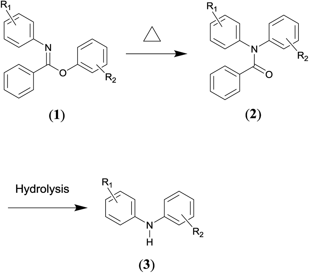 | ||
| Scheme 1 | ||
Other methods for the preparation of N,N-diarylbenzamides generally involve C–N cross-coupling of acyclic secondary amides with aryl halides,15 and the Ullmann-type cross-coupling reactions between aryl halides and anilines typically represents the alternative route to afford diphenylamines.16 However, the cross-coupling methods often require metal-catalysts, sophisticated ligands, high temperatures and long reaction times.15,16 These factors are undesirable from economic, environmental and operational safety viewpoints considering the cost of noble metal catalysts (e.g., palladium) and sophisticated ligands as well as the strict regulations to remove trace amounts of metal species in the synthesis of medicinally active molecules. What is more, only a limited substrate scope can be effected via cross-coupling reactions.17 Therefore, the Chapman rearrangement is the method of choice in numerous synthetic routes of practical relevance.
It is an intramolecular reaction via four-membered transition state, as confirmed by previous experimental studies,18,19 in which a 1,3 shift of an aryl group from oxygen to nitrogen occurs. The appealing usefulness of the rearrangement specifically lies in several aspects. Firstly, it is a unimolecular reaction, only the desired product is resulted as the end product. Hence, the operation and work-up procedures involved are simple. Secondly, it has been carried out successfully with a wide substrate scope, and the yields have generally been high.20 Thirdly, the reactant (1) can be readily prepared by the utilization of simple as well as widely accessible starting materials.21
Whereas, the main concern is that a high temperature (e.g., typically 473.15–573.15 K) is required to facilitate the aromatic migrating process.22 While if the temperature is too high, which is far above the temperature needed to provide the activation energy, it would decompose the reactant or product in a large number of cases.23,24 Furthermore, the situation becomes complex for the cases that are markedly exothermic. For example, the temperature was observed to have risen as much as 30 K for the reactant R1![[double bond, length as m-dash]](https://www.rsc.org/images/entities/char_e001.gif) o–COOMe, R2H (in Scheme 1) when operating the rearrangement at 543.15 K on a very small laboratory scale.24 More importantly, the temperature increase depends partly on the scale of the operation, which is especially true for batch-wise processes.24 Consequently, the Chapman rearrangement ideally needs to be run at an optimal temperature in a well-controlled manner.
o–COOMe, R2H (in Scheme 1) when operating the rearrangement at 543.15 K on a very small laboratory scale.24 More importantly, the temperature increase depends partly on the scale of the operation, which is especially true for batch-wise processes.24 Consequently, the Chapman rearrangement ideally needs to be run at an optimal temperature in a well-controlled manner.
It is worth noting that the Chapman rearrangement reactions are still overwhelmingly carried out in batch-wise operations. From an operational viewpoint, it is difficult to operate and manage high temperature reactions in batch reactors, in particular for large scale applications. In industrial practices, reaction temperatures over 473.15 K are generally outside of normal operating ranges for most standard batch reactors in pharmaceutical production facilities.25 Large-volume high-temperature/high-pressure customized reactors, on the other hand, are very bulky as well as costly.25 In spite of the continuous innovations in batch reactors, precise thermal control to ensure a spatially uniform temperature environment remains a big challenging problem for conventional batch reactors,26 particularly when high temperature reactions of exothermic nature are considered because of the strong nonlinear dynamics and the intrinsically unsteady behavior of batch reactors.27 Since the spatial temperature gradients are unlikely to be completely eliminated, the long-time exposure of reaction mixture to inhomogeneous heating is problematic, and may cause severe decease in the yields. Worse still, the scale up of batch processes from laboratory size to commercial scale is non-trivial, which comprises complicated, painfully long, case specific and expensive procedures.13 When upscaling a batch reactor to larger sizes, the volume increases much faster than the external surface area, so if a small reactor is operated under an isothermal condition, increasing its volume would move the reactor towards adiabatic operational regime.28 In this case, safety concerns would be raised as a result. It is thus highly desired that the Chapman rearrangement could be alternatively carried out in a more convenient, efficient, controllable and safer approach without scale-up hurdles.
Fortunately, the rapid development of micro-reaction technology (MRT) has provided new alternatives for synthetic organic chemistry and the chemical industry.25 Chemical reactions could be conveniently performed in continuous-flow microreactors. Due to the high surface-to-volume ratio, exceptional heat and mass transfer efficiencies are enabled for microreactors, in which the temperatures can be uniformly and accurately controlled in a timely manner.29 Besides, the closed system combined with small hold-up volume provide an inherently safe environment to implement high temperature, exothermic, hazardous and even explosive reactions.25 Moreover, scale up can be straightforward for microreactors via the numbering-up strategy or simply adopting longer channels while maintaining the same dimensionless transport characteristics or running for an extended period of time to increase throughput.30,31 Accordingly, the continuous-flow microreactors have attracted a great deal of attention in organic chemistry community.
The process design and optimization of continuous-flow processes can be effectively accelerated with the help of detailed knowledge of the fluid flow dynamics, heat and mass transfer characteristics including chemical kinetics. Conventionally, the employment of exhaustive experiments to assess the importance of various parameters in large scale applications is a tedious, time-intensive as well as costly task, especially for those cases in which the reactants/reagents/catalysts are not commercially available on the market, but needs to be in-house prepared. For this reason, computational fluid dynamics (CFD) technique can be employed as a powerful tool to acquire an in-depth understanding on the processes as well as to identify the crucial parameters for the highly efficient design and optimization of large-scale applications.
Many synthetic reactions requiring high temperatures have been successfully implemented in continuous-flow microreactors.32,33 However, to our best knowledge, the Chapman rearrangement has never been attempted in continuous-flow microreactors in the open literature, despite of all the potential benefits. Ergo, the Chapman rearrangement was carried out in continuous-wise microreactors in this work in order to explore its performance and behavior in this new reaction fashion. Although rearrangement of this type has been heavily investigated in batch processes since its discovery, its reaction performance and behavior in microreactors were never discussed and analyzed before. As is often the case, continuous-wise reaction behaviors are prone to deviate substantially from the batch-wise counterparts. With this in mind, it becomes necessary to study the detailed continuous-wise reaction behaviors in order to provide new knowledge and insights into the rearrangement performed in continuous manner, and thus improve upon the conventional batch mode as well as define the optimal operating regimes in the continuous-flow processes. In addition, chemical kinetics could be coupled with the CFD model, thus allowing the development of a robust predictive platform for further reliable process design and optimization.
In this work, an initial understanding on the Chapman rearrangement was first obtained by examining the effects of temperature and reaction time. Then, the performance of this rearrangement in a continuous-flow microreactor was investigated for a number of reactants. Subsequently, the reaction behavior was detailedly explored and the corresponding kinetic model was formulated to describe the reaction process in a quantitative way. Following that, scale up of both the continuous-flow and batch-wise approaches was discussed in order to showcase the easy scale-up of flow devices. A CFD model coupled with the obtained chemical kinetics was developed to aid the analysis of transport characteristics of the continuous-flow processes finally. The results reported would shed new lights on the developments and applications of continuous-flow method for the classical Chapman rearrangement that requiring harsh high temperatures.
2. Experimental
2.1 Materials and analytics
Since the reactants used in this work were not commercially available, they were in-house prepared according to Scheme 2. The detailed preparation procedures are elaborated in the ESI (Pages S2–S8).†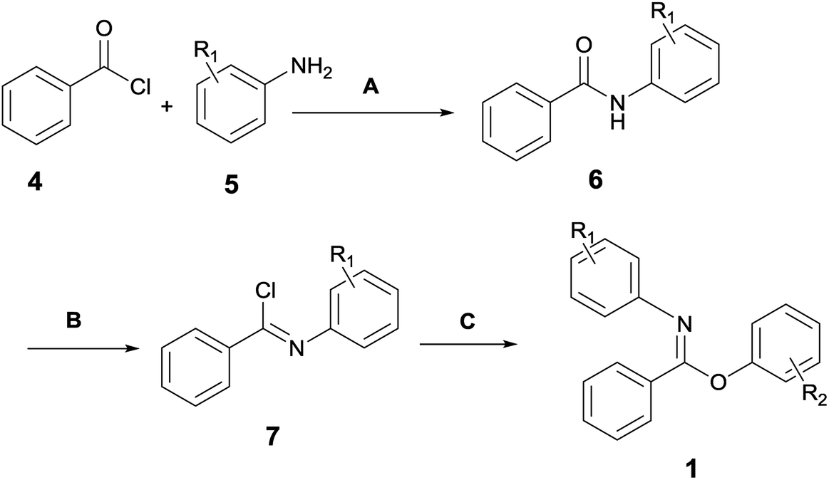 | ||
| Scheme 2 General procedure for preparing the Chapman rearrangement reactants. | ||
Melting points were measured on a WRS-1B digital melting-point apparatus. HRMS was measured by the Bruker micrOTOF spectrometer. HPLC analysis was performed on an Agilent 1200 HPLC system with UV detector and PHENOMENEX OOG-4375-E0 column (250 mm × 4.6 mm). Eluents were composed of H2O (A) and CH3CN (B) with VA/VB = 40![[thin space (1/6-em)]](https://www.rsc.org/images/entities/char_2009.gif) :60–10:90. Peaks were found at λ 220 nm with a flow rate of 1.0 ml min−1. 1H (400 MHz) and 13C (100 MHz) NMR were analyzed on a Bruker Avance 400 spectrometer in d6-DMSO using tetramethyl silane (TMS) as the internal standard. The chemical shifts were given in δ (ppm) units relative to TMS. Coupling constant (J) values were given in Hz. Multiplicities were designated by the following abbreviations: s, singlet; d, doublet; t, triplet; q, quartet; br, broad; m, multiplet. Products were purified by flash column chromatography on silica gel purchased from Qingdao Haiyang Chemical Co., Ltd.
:60–10:90. Peaks were found at λ 220 nm with a flow rate of 1.0 ml min−1. 1H (400 MHz) and 13C (100 MHz) NMR were analyzed on a Bruker Avance 400 spectrometer in d6-DMSO using tetramethyl silane (TMS) as the internal standard. The chemical shifts were given in δ (ppm) units relative to TMS. Coupling constant (J) values were given in Hz. Multiplicities were designated by the following abbreviations: s, singlet; d, doublet; t, triplet; q, quartet; br, broad; m, multiplet. Products were purified by flash column chromatography on silica gel purchased from Qingdao Haiyang Chemical Co., Ltd.
2.2 Experimental setup and method
The graphic representation of the flow system is shown in Fig. 1. Unless otherwise specified, the adopted microreactor consisted of a 250 μl piece of stainless steel coil with an internal diameter (d) of 0.588 mm and a length (L) of 920 mm. In the experiments, the reactant in tetraethylene glycol dimethyl ether (tetraglyme) was introduced into the microreactor by a syringe pump (Fusion 400, Chemyx). A check value was installed between the pump and the microreactor in order to prevent the reverse flow. The microreactor was immersed in an oil bath to ensure the required reaction temperature. A stainless termination loop with an internal diameter of 0.588 mm at room temperature was connected to the microreactor. Because the Chapman rearrangement required a certain high temperature, so it stopped proceeding once the reaction mixture flowing into the termination loop. The whole system was pressurized by a back pressure valve to avoid boiling point limitations. The use of high-boiling solvent tetraglyme (bp 548.15 K) could make the operation safer by considerably decreasing the pressure needed to overcome the boiling point limitations.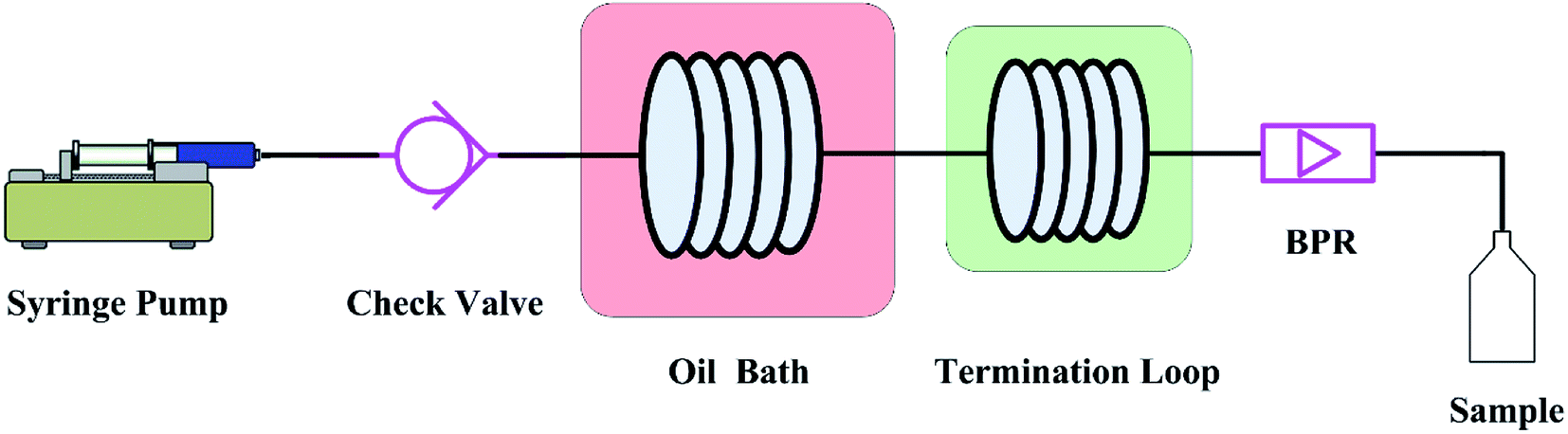 | ||
| Fig. 1 Schematic overview of the experimental system for the Chapman rearrangement. | ||
The reaction time inside the microreactor was accurately controlled via varying the flow rate. The quenched effluent was collected after a period of the corresponding residence time in the flow system. The collected samples were subject to further purification and quantitative analysis.
Additionally, unless otherwise stated the relevant batch-wise syntheses were carried out in a 25 ml standard round-bottomed flask with reaction volume of 10 ml in order to compare the two methods. The analytical and spectral data for all the obtained reactants and products are given in the ESI (Pages S2–S8 and S13–S18 for the reactants; Pages S9–S11 and S19–S24 for the products).†
3. Results and discussion
3.1 The Chapman rearrangement
The continuous-flow microreactor provided a convenient means to conduct high temperature reactions. In this approach, the reactant was continuously delivered into the microreactor with a pump, then it flowed through the reaction channel set at the desired temperature with chemical transformation occurred during the course. After a period of the residence time, the reaction mixture was collected when it exited the system. No external intervention was needed after the system started up. The continuous-flow process allows this rearrangement to operate in a safer and more controllable manner. The effects of temperature (T) and reaction time (tR) were first examined to have an initial understanding on this reaction based on the reactant 2,6-dichloro-phenyl N-phenyl benzimidate.Fig. 2(a) reveals the temperature dependence of this rearrangement operated in a microreactor. It is of interest to note that a temperature increase from 493.15 to 533.15 K resulted in about 4.5 times higher conversion (X), but the increase in conversion slowed down with further increase in the temperature. It is worth pointing out that over 92% conversion was achieved within only 5 min at 533.15 K, and over 99% conversion was realized in just 2.5 min at 553.15 K.
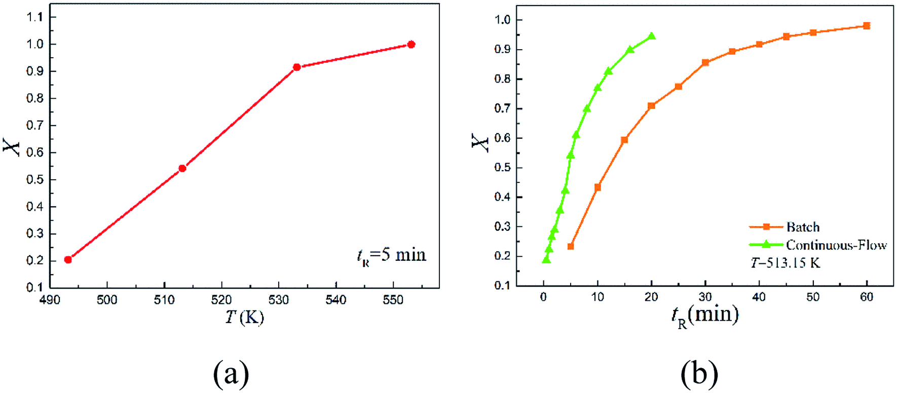 | ||
| Fig. 2 Effects of temperature and reaction time on the conversion for 2,6-dichloro-phenyl N-phenyl benzimidate. (a) Effect of temperature in a microreactor for tR = 5 min. (b) Effect of reaction time in a microreactor and a batch reactor. | ||
Fig. 2(b) shows the reaction time dependence of the rearrangement in both the microreactor and the batch reactor. As can be seen, more than 94.42% reactant was quickly converted into product within 20 min in continuous-flow approach, but the batch-wise reaction was much slower. Approximately, it took about 3 times more time for the batch-wise reaction to reach the similar final conversion.
Following the initial examination of the reaction conditions (Fig. 2), a group of reactants was tested as shown in Table 1 to evaluate the performance of the continuous-flow method.
| Entry | Product | tR (min) | T (K) | Conversiona | Isolated yield |
|---|---|---|---|---|---|
| a Conversion was quantified by offline HPLC analysis of aliquots of reaction mixture with internal standard of diphenyl ether (bp 531.7 K). | |||||
| 1 | 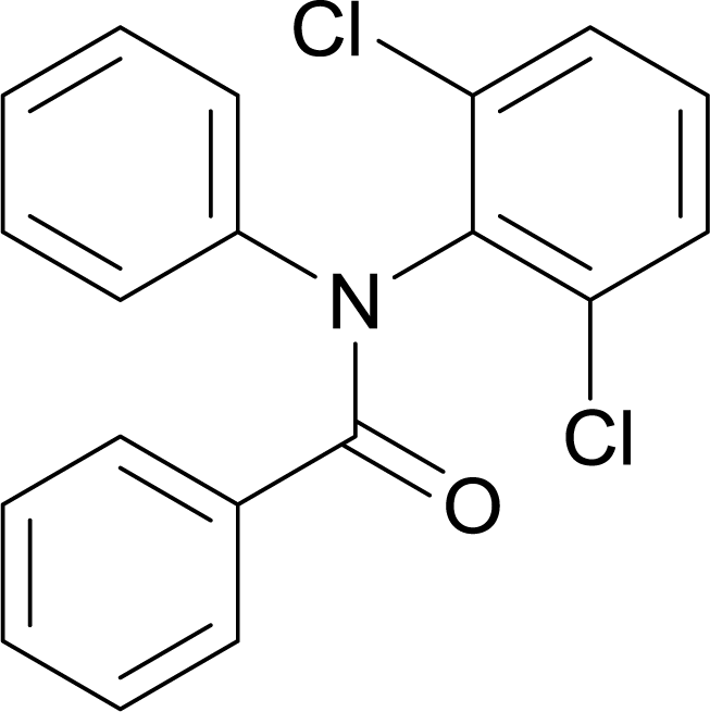 |
20 | 513.15 | 94.42% | 81% |
| 2 | 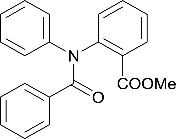 |
20 | 513.15 | >99% | 82.8% |
| 3 | 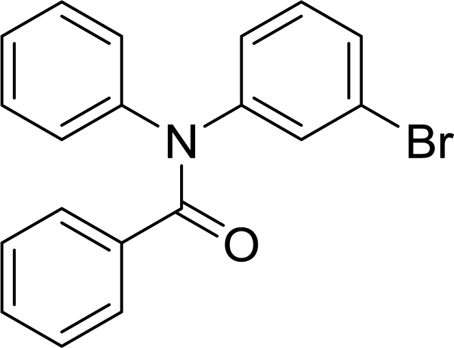 |
20 | 563.15 | 92% | 73.8% |
| 4 | 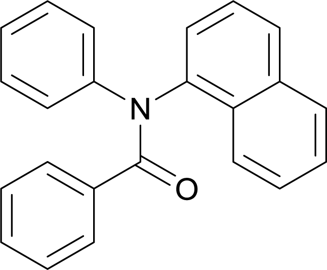 |
20 | 563.15 | 78.5% | 67.4% |
| 5 | 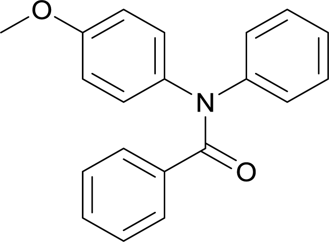 |
20 | 563.15 | 72.4% | 65.9% |
| 6 | 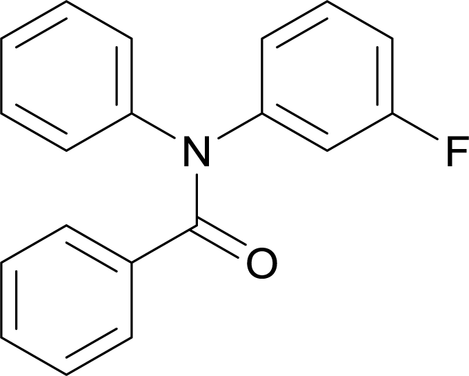 |
20 | 563.15 | 83.3% | 53.8% |
It appears that high conversions were achieved in only 20 min in the continuous-flow microreactors compared to that many hours were consumed in batch-wise approaches.2,19,21,34 In addition, it is important to emphasize that no by-products were found in these tested reactions. The results shown in Table 1 illustrate that the Chapman rearrangement could be efficiently performed in continuous-flow microreactors.
3.2 Chemical kinetics
Although chemical kinetics is useful to understand the reaction behavior as well as plays a significant role in process design and optimization, the detailed kinetics of this continuous-flow Chapman rearrangement has never been reported. Efforts were thus undertaken in the present study to explore the intensified kinetic behavior. Since it is a unimolecular reaction,18,19 the rate of transformation of the reactant was derived as
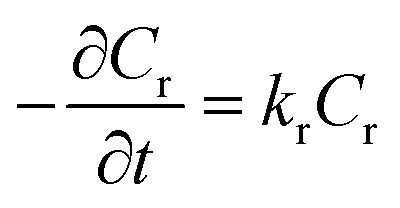 | (1) |
Integrating and applying the condition that at t = 0 s, Cr= Cr,0 (initial reactant concentration), we arrived at
| Cr = Cr,0e−krt | (2) |
In order to determine the value of kr from the experimental data, taking the natural log of eqn (2) leaded to
| ln(Cr) = ln(Cr,0) − krt | (3) |
As is known, the Arrhenius equation quantitatively correlates the reaction rate constant with the corresponding energy of activation (Ea, kJ mol−1) and pre-exponential factor (A, 1/s) as
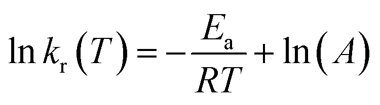 | (4) |
The kinetic parameters were calculated from the equations below 35,36
| ΔH† = Ea − RT | (5) |
 | (6) |
 | (7) |
The typical reactants 2,6-dichloro-phenyl N-phenyl benzimidate and 2-carbomethoxy-phenyl N-phenyl benzimidate were employed to study the detailed kinetics because they are of practical importance in the syntheses of diclofenac sodium13 and quinacrine,9,10 respectively. A series of kinetic experiments were conducted in the microreactor at 493.15, 513.15, 533.15, and 553.15 K with the reactant concentration of 0.3 mol L−1. Reactant concentrations over time were closely followed in order to obtain the corresponding reaction rate constants. Fig. 3 shows the variations of reactant concentrations over time. Obviously, the rearrangement is highly temperature-dependent, and increasing temperature would dramatically facilitate the transformation.
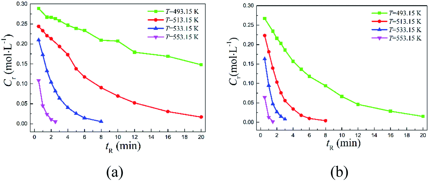 | ||
| Fig. 3 Measured reactant concentrations vs. residence time in a continuous-flow microreactor at varying temperatures for (a) 2,6-dichloro-phenyl N-phenyl benzimidate, (b) 2-carbomethoxy-phenyl N-phenyl benzimidate. | ||
The conversions with time are depicted in Fig. 4. Specifically, 2,6-dichloro-phenyl N-phenyl benzimidate reached only about 50.73% conversion at 493.15 K within 20 min of reaction time, but over 94.42% reactant was successfully converted within the same period of reaction time (20 min) when increasing the temperature to 513.15 K. Further increasing it to 553.15 K, the conversion was complete in 2.5 min. Note that over 95% conversion was realized in 20 min at 493.15 K for 2-carbomethoxy-phenyl N-phenyl benzimidate, and almost complete conversion was reached in 1.5 min at 553.15 K.
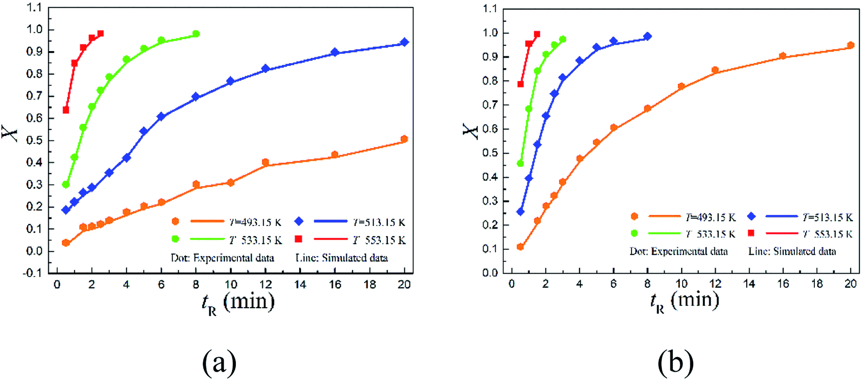 | ||
| Fig. 4 Comparison of measured and simulated conversions vs. reaction time in a continuous-flow microreactor at varying temperatures for (a) 2,6-dichloro-phenyl N-phenyl benzimidate, (b) 2-carbomethoxy-phenyl N-phenyl benzimidate (scattered dots: experimental data; solid lines: CFD simulated data). | ||
The data shown in Fig. 4 offers valuable information for aiding the choices of optimum operating variables including the residence times and reaction temperatures. Because in practical process design, it is often challenging to define the optimal operating conditions. Higher temperature means more energy consumption. It might not be the best practice to simply select the highest possible temperature for large scale applications, as conversion need to be trade-off with energy consumption and the overall operating cost.
The reaction rate constants at varying temperatures were obtained via fitting eqn (3) to the experimental data. The rate constants of reaction as well as the corresponding kinetic parameters (ΔG†, ΔH† and ΔS†) are tabulated in Tables 2 and 3.
| T (K) | kr (1/s) | ΔG† | ΔH† | ΔS† |
|---|---|---|---|---|
| a Ea = 143.757 kJ mol−1, A = 5.826 × 10¹³ (1/s). | ||||
| 493.15 | 0.0337 | 136.739 | 139.657 | −5.918 |
| 513.15 | 0.1389 | 136.412 | 139.491 | −6.000 |
| 533.15 | 0.4893 | 136.317 | 139.325 | −5.642 |
| 553.15 | 1.51 | 136.417 | 139.159 | −4.956 |
| T (K) | kr (1/s) | ΔG† | ΔH† | ΔS† |
|---|---|---|---|---|
| a Ea = 118.923 kJ mol−1, A = 6.126 × 10¹¹ (1/s). | ||||
| 493.15 | 0.1471 | 130.697 | 114.823 | 32.188 |
| 513.15 | 0.5515 | 130.529 | 114.657 | 30.931 |
| 533.15 | 1.2172 | 132.277 | 114.491 | 33.360 |
| 553.15 | 3.7164 | 132.275 | 114.325 | 32.451 |
Arrhenius correlations between reaction rate constants and inverse temperatures are plotted in Fig. 5. The energy of activation Ea and pre-exponential factor A were obtained from the slope and intercept, respectively (Tables 2 and 3).
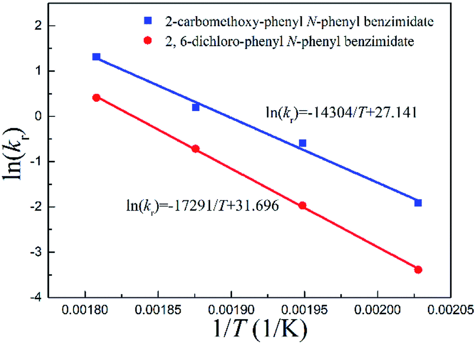 | ||
| Fig. 5 Arrhenius correlations between reaction rate constants and inverse temperatures for continuous-flow processes. | ||
Fig. 5 quantitatively indicates that the higher the temperature, the larger the reaction rate constant for the Chapman rearrangement. Note that the reaction rate constants of 2-carbomethoxy-phenyl N-phenyl benzimidate are larger than the counterparts of 2,6-dichloro-phenyl N-phenyl benzimidate. This fact justifies the better conversions of 2-carbomethoxy-phenyl N-phenyl benzimidate compared to those of 2,6-dichloro-phenyl N-phenyl benzimidate at the same operating conditions as shown in Fig. 4.
3.3 Scale-up
The throughput of a single channel on sub-millimeter scale is often too low to supply large amounts of materials to meet commercial needs. The straightforward approaches to increase the throughput involve numbering up the flow devices or adopting longer channels while maintaining the same dimensionless transport characteristics or simply running the reaction for an extended period of time. However, numbering-up of sub-milliliter volume microreactor is not industrially preferred taking into account the complexity of simultaneously controlling flows and temperatures in numerous microreactors in parallel. On the other hand, the exceedingly long microchannel results in a very high pressure drop. Alternatively, it was suggested to first scale the microchannel to a larger size while maintaining transport characteristics and then number up a smaller number of flow devices.37Based on these considerations, the sub-millimeter microreactor (MR1) was scaled up to a 16-fold larger volume by employing a larger-sized stainless steel coil (MR2). The comparison was made such that the diameter and length were changed while the residence time was retained constant.
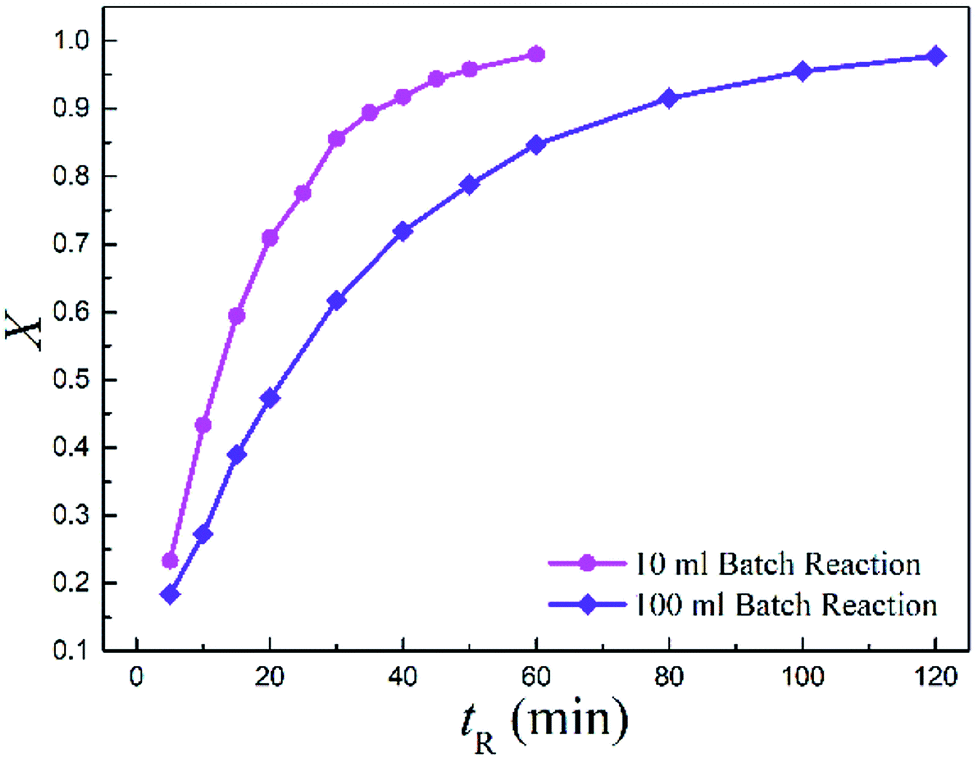
Meanwhile, the batch-wise reaction volume was scaled from 10 (BR1) to 100 ml (BR2) as well. Notably, the conversion dramatically decreased by more than 33.3% when upscaling the batch reaction to a 10 times larger volume.
Fig. 6 displays the conversions with time for the two batch reactors. It is observed that the reaction in larger volume was much slower than in the small one, suggesting a strong scale-up effect for the conventional batch-wise synthesis.
 | ||
| Fig. 6 Measured conversions vs. reaction time for the two batch reactors (T = 513.15 K and Cr = 0.3 mol L−1). | ||
However, in stark contrast, only a very slight decrease was found in the conversion when increasing 16-fold the reaction volume for the continuous-flow method. Clearly, it exemplified the flow system could be easily scaled to a larger dimension without palpably affecting the reaction results. More importantly, no further optimization was needed. The production rate of MR1 was 62 mg h−1, while it reached 0.949 g h−1 for MR2. The production rate of MR2 represents a 15.31-fold increase in scale, which could be translated to 22.776 g product per day. The scale-up experiments demonstrated the simplicity of scaling up continuous-flow Chapman rearrangement.
3.4 CFD modelling
It is difficult to experimentally measure the transport characteristics (e.g., species concentration distributions, temperature distributions, etc.) inside the microreactor used in this work because it is made of opaque stainless steel and has a very small dimension. CFD modelling can thus be used to obtain an in-depth understanding on the transport characteristics inside the microreactors, as well as a powerful tool in the relevant process design and optimization. Since the microreactors used are circular tubes, a 2D axisymmetric computational domain was reasonably assumed to decrease the computing burden. The fluid flow inside was laminar with Reynolds number in the range of 0.13–0.74. The fluid was assumed to be constant density considering that it was pressurized in the system.The continuity and momentum equations were given by the Navier–Stokes equations
| ∇·(ρu) = 0 | (8) |
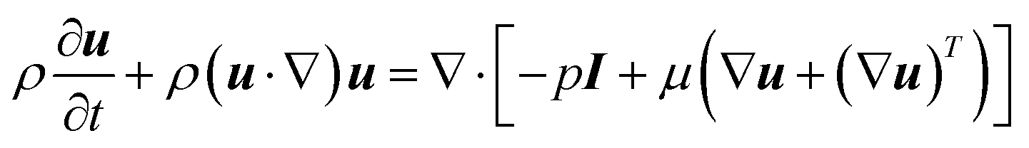 | (9) |
The energy conservation equation in the microreactor was modelled as
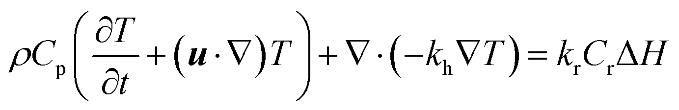 | (10) |
The mass conservation of the reactant in the microreactor was formulated as
 | (11) |
The CFD simulated values of conversion are compared to the corresponding experimental data as shown in Fig. 4. As can be seen, the simulated conversions (solid lines) matched well with the experimental data (scattered dots).
The simulated reactant concentration distributions inside MR1 and MR2 are shown in Fig. 7. Be noted that the geometries were scaled by a factor of 200 for both MR1 and MR2 as they had very large aspect ratios. Interestingly, it is noted that the plug flow pattern was very closely presented in MR1, while the flow profile obviously deviated from the ideal plug flow in MR2.
 | ||
| Fig. 7 Simulated reactant concentration distributions inside microreactors: (a–c) for MR1, (d–f) for MR2 (2,6-dichloro-phenyl N-phenyl benzimidate, T = 513.15 K, tR = 20 min and Cr = 0.3 mol L−1). | ||
Fig. 8 exhibits the temperature distributions in MR1 and MR2. The CFD simulations revealed that the reaction fluid was heated up to 513.15 K in 4.03 seconds for MR1 and in 5.88 seconds for MR2 respectively after it was pumped into the flow system from room temperature. The similarly distributed temperatures in MR1 and MR2 ensured that the reaction results were close to each other. Nevertheless, the deviation from plug flow pattern in MR2 might be the cause for the slight variation in the conversion as compared to that of MR1 (Table 4).
 | ||
| Fig. 8 Temperature distributions in MR1 and MR2 (2,6-dichloro-phenyl N-phenyl benzimidate, T = 513.15 K, tR = 20 min and Cr = 0.3 mol L−1). | ||
| Reactor | Geometric parameters | Reaction volume | Reaction time | Conversionc | Isolated yield |
|---|---|---|---|---|---|
| a Internal diameter (d) and length (L) of the microreactor.b Standard round-bottomed flask, VR is the total reactor volume.c Conversion was quantified by offline HPLC analysis of aliquots of reaction mixture with internal standard of diphenyl ether.d Not isolated. | |||||
| MR1 | d = 0.588 mma, L = 920 mma | 0.25 ml | 20 min | 94.42% | 81% |
| MR2 | d = 1.755 mma, L = 1650 mma | 4.0 ml | 20 min | 92.7% | 78% |
| BR1 | VR = 25 ml flaskb | 10 ml | 20 min | 70.92% | −d |
| BR2 | VR = 250 ml flaskb | 100 ml | 20 min | 47.27% | −d |
The simulated values of conversion and experimental data are compared in Fig. 9 with the mean absolute error of 1.06%. Almost all the simulated data fell within 3% absolute error with the experimental data. Therefore, good agreement was obtained between the simulated values and the measured data, which confirmed that the CFD model was robust and could be further employed as a powerful predictive platform in the process design and optimization when translating the developed continuous-flow approach into industrial practices.
 | ||
| Fig. 9 Comparison of experimental and CFD simulated conversions. | ||
4. Conclusion
In this work, a microreactor-based continuous flow method was developed for the high temperature Chapman rearrangement. The process was found to operate in a highly controlled and safer manner as compared to the conventional batch mode. High conversions were reached for a range of reactants within short residence times (≤20 minutes). The continuous-flow rearrangement was several times faster than the batch-wise counterpart. The detailed kinetics of this reaction, using 2,6-dichloro-phenyl N-phenyl benzimidate and 2-carbomethoxy-phenyl N-phenyl benzimidate as the representative reactants, was explored at varying temperatures to understand the intensified reaction behavior, and was modelled based on the obtained experimental data. The determined kinetic parameters indicated that the activation energy of 2,6-dichloro-phenyl N-phenyl benzimidate is higher than that of 2-carbomethoxy-phenyl N-phenyl benzimidate. The continuous-flow synthesis was scaled up 16 times in volume by increasing the diameter of the microreactor while maintaining the residence time. Only a very slight decrease was observed in the conversion for the larger-sized system. By contrast, upscaling the batch-wise reaction to a 10 times larger volume resulted in a dramatic decrease in the conversion. The simplicity of scaling up continuous-flow system was well demonstrated. A CFD model coupling with the rearrangement kinetics was developed and well validated against the experimental data, which provided a robust platform for guiding the process design and optimization of the continuous-flow Chapman rearrangement.Conflicts of interest
There are no conflicts to declare.Acknowledgements
This work was financially sponsored by Shanghai Pujiang Program (No. 18PJ1401100) and State Key Laboratory of Chemical Engineering (No. SKL-ChE-18A03).References
- A. W. Chapman, J. Chem. Soc., 1929, 569–572 RSC.
- F. Benington, E. V. Shoop and R. Poirier, J. Org. Chem., 1953, 18, 1506 CrossRef CAS.
- G. Bock, Chem. Ber./Recl., 1967, 100, 2870–2884 CrossRef CAS.
- V. Burdukovskii, D. Mognonov, S. Allayarov, S. Botoeva and Z. P. Mazurevskaya, Russ. Chem. Bull., 2004, 53, 1773 CrossRef CAS.
- A. Kaczor, L. M. Proniewicz, R. Almeida, A. Gomez-Zavaglia, M. L. S. Cristiano, A. M. M. Beja, M. R. Silva and R. Fausto, J. Mol. Struct., 2008, 892, 343–352 CrossRef CAS.
- A. Imberdis, G. Lefevre, P. Thuery and T. Cantat, Angew. Chem., Int. Ed., 2018, 57, 3084–3088 CrossRef CAS PubMed.
- A. Kumar and A. K. Mishra, J. Pharm. BioAllied Sci., 2015, 7, 81–85 CrossRef CAS PubMed.
- J. Wagner, M. L. Wagner and W. A. Hening, Ann. Pharmacother., 1998, 32, 680–691 CrossRef CAS PubMed.
- M. Kimura, J. Chem. Soc., Perkin Trans. 2, 1987, 205–209 RSC.
- W. G. Dauben and R. L. Hodgson, J. Am. Chem. Soc., 1950, 72, 3479–3480 CrossRef CAS.
- L. Peterson, A. Douglas and R. Tolman, J. Heterocycl. Chem., 1981, 18, 659–662 CrossRef CAS.
- F. Lopez-Munoz, C. Alamo, G. Rubio and E. Cuenca, Prog. Neuropsychopharmacol. Biol. Psychiatry, 2004, 28, 205–208 CrossRef CAS PubMed.
- I. Grafe, H. Schickaneder and K. H. Ahrens, US Pat., US4978773, 1990.
- F. Nohara, UK Patent, GB1532087, 1978.
- J. D. Hicks, A. M. Hyde, A. M. Cuezva and S. L. Buchwald, J. Am. Chem. Soc., 2009, 131, 16720–16734 CrossRef CAS PubMed.
- J. F. Hartwig, Angew. Chem., Int. Ed., 1998, 37, 2046–2067 CrossRef CAS PubMed.
- A. R. Katritzky and A. J. Cozens, J. Chem. Soc., Perkin Trans. 1, 1983, 11, 2611–2615 RSC.
- K. B. Wiberg and B. I. Rowland, J. Am. Chem. Soc., 1955, 77, 2205–2209 CrossRef CAS.
- O. H. Wheeler, F. Roman and O. Rosado, J. Org. Chem., 1969, 34, 966–968 CrossRef CAS.
- J. Schulenberg and S. Archer, Org. React., 2004, 14, 1–51 Search PubMed.
- O. H. Wheeler, F. Roman, M. V. Santiago and F. Quiles, Can. J. Chem., 1969, 47, 503–504 CrossRef CAS.
- H. M. Relles, J. Org. Chem., 1968, 33, 2245–2249 CrossRef CAS.
- A. W. Chapman, J. Chem. Soc., 1927, 1743–1751 RSC.
- M. M. Jamison and E. Turner, J. Chem. Soc., 1937, 0, 1954–1959 RSC.
- B. Gutmann, D. Cantillo and C. O. Kappe, Angew. Chem., Int. Ed., 2015, 54, 6688–6728 CrossRef CAS PubMed.
- M. Huzmezan, B. Gough and S. Kovac, Proceedings of the 2002 American Control Conference (IEEE Cat. No. CH37301), 2002, vol. 2, pp. 1156–1161 Search PubMed.
- F. Caccavale, M. Iamarino, F. Pierri and V. Tufano, Control and Monitoring of Chemical Batch Reactors, Springer, London, 2011 Search PubMed.
- J. Worstell, Batch and Semi-Batch Reactors-Practical Guides in Chemical Engineering, Butterworth-Heinemann, Waltham, 2015 Search PubMed.
- N. Kockmann and D. M. Roberge, Chem. Eng. Technol., 2009, 32, 1682–1694 CrossRef CAS.
- K. S. Elvira, X. C. I. Solvas, R. C. R. Wootton and A. J. deMello, Nat. Chem., 2013, 5, 905–915 CrossRef CAS PubMed.
- S. G. Newman and K. F. Jensen, Green Chem., 2013, 15, 1456–1472 RSC.
- T. Razzaq, T. N. Glasnov and C. O. Kappe, Eur. J. Org. Chem., 2009, 9, 1321–1325 CrossRef.
- T. Razzaq and C. O. Kappe, Chem.–Asian J., 2010, 5, 1274–1289 CAS.
- R. Barclay, Can. J. Chem., 1965, 43, 2125–2131 CrossRef CAS.
- J. Boche and O. Runquist, J. Org. Chem., 1968, 33, 4285–4286 CrossRef CAS.
- K. J. Laidler and M. C. King, J. Phys. Chem., 1983, 87, 2657–2664 CrossRef CAS.
- Y. J. Zhang, S. C. Born and K. F. Jensen, Org. Process Res. Dev., 2014, 18, 1476–1481 CrossRef CAS.
Footnote |
| † Electronic supplementary information (ESI) available. See DOI: 10.1039/c9ra01347d |
| This journal is © The Royal Society of Chemistry 2019 |