 Open Access Article
Preparation and properties of PTFE hollow fiber membranes for the removal of ultrafine particles in PM2.5 with repetitive usage capability
Huan Xua,
Wangyong Jinb,
Feng Wangac,
Chengcai Lia,
Jieqi Wanga,
Hailin Zhu*ac and
Yuhai Guo *a
*a
aZhejiang Provincial Key Laboratory of Fiber Materials and Manufacturing Technology, Zhejiang Sci-Tech University, Hangzhou, 310018, China. E-mail: gyh@zstu.edu.cn; zhhailin@163.com
bZhejiang Dong Da Environment Engineering CO., LTD, Zhuji 311800, China
cZhejiang Kertice Hi-Tech Fluor-Material Co., LTD, Huzhou 313000, China
First published on 14th November 2018
Abstract
This study reveals the first attempt to apply PTFE hollow fiber membranes for removing ultrafine particles in PM2.5. The asymmetric polytetrafluoroethylene (PTFE) hydrophobic hollow fiber membranes were prepared through a cold pressing method including paste extrusion, stretching and heating. The reduction ratio, stretching ratio and heating temperature have influences on the morphology, structure, porosity, shrinkage ratio, tensile strength and permeability of the PTFE hollow fiber membranes. The morphological properties of the PTFE hollow fiber membrane were studied using field emission scanning electron microscopy (FESEM). The increase of stretching ratio can improve the pore size and porosity of the hollow membrane, but be negative for the mechanical properties. By changing the reduction ratio we can obtain different inner diameter PTFE hollow fiber membranes. Finally, the PTFE hollow fiber membranes were tested for their performances in the removal of ultrafine particles in PM2.5. The PTFE hollow fiber membranes had the microstructure of nodes interconnected by fibrils, designed to possess the synergistic advantages of porous filters and fibrous filters with a sieve-like outer surface and a fibrous-like porous substrate. Under dead-end filtration, the filtration efficiency is related to the wall thickness, pore size and porosity of the membranes. The air filtration achieved was higher than 99.99% for PM2.5 and 90% for PM0.3, indicating that all the prepared PTFE hollow fiber membranes exhibited satisfactory removal of ultrafine particles performances. Because of the hydrophobicity, PTFE hollow fiber membranes have self-cleaning ability and a large dust-holding capacity of >120 g m−2, slowing down membrane fouling. The fouled filter media after washing retained a high filtration efficiency without obvious deterioration. The hydrophobic PTFE hollow fiber membranes developed in this work exhibited potential applications in air filtration.
1. Introduction
Over the past decade, air pollution has become a global issue, especially in developing countries. Fine particulate matter (PM) is the most harmful matter and has a severe influence on human health, air quality, and climate.1–3 As we all know, PM is a complex mixture of extremely small particles and moisture that can penetrate the human lungs and enter into the body circulation system. Exposure to PM pollution can lead to heart disease, and lung disease, even cancer.4,5 People are paying more attention to outdoor air quality but neglecting indoor air quality. Sometimes, the indoor air quality has become of great importance as indoor air contains two to five times higher concentrations of pollutants than outdoor air.6 It is necessary and urgent to ensure effective protection for the public from the present hazy days.7,8 For individual outdoor protection, some efforts have been made.9,10 Facial masks are used to prevent the inhalation of PM2.5 during outdoor activities. But we should care about indoor air quality, such as that in a modern commercial building or our house.11–13 The PTFE hollow fiber membrane air cleaner is employed to improve the air-conditioned indoor air.To remove or filter PMs from polluted air, many techniques have been developed, such as such as cyclones, electrostatic precipitators and fibrous filters including high-efficiency particulate air filters and nanofiber filters.14,15 The most well-known air filtration mechanisms are direct interception, Brownian diffusion, inertial impaction, and gravity settling.16–18 In the past decade, electrospun nanofibers have been used as fibrous filters for air filtration because of the extremely fine diameters.10,19–26 However, most of these membranes still suffer from filter' robustness, antiwear properties and low production, which limit the practical application of electrospun nanofibers.27,28 High-efficiency particulate air filter is constructed from fibers which arrange into random layers and stack onto one another. This type of filter has a short service life because of its symmetric structure. After depth air filtration, different sizes of PMs are captured by filters and permeate inside the filters, making cleaning and reuse more difficult.17,29,30
Comparing the conventional air filters, PTFE hollow fiber membrane is an attractive membrane material for air filtration due to superior hydrophobicity, self-supported, high packing density and module fabrication.31,32 Thus far, PTFE hollow fiber membranes have been widely exploring and adopted for versatile application, such as water treatment, membrane distillation, membrane bioreactor, membrane aeration bioreactor.33–36
PTFE is widely used in the field of air filtration, but the main products are PTFE flat membranes and PTFE bag filter. Ning Mao37 discussed the influencing factors on filtration performances of PTFE membranes filters. Zhang Nan38 improved filtration properties of hydroentangled PTFE/PPS fabric filters caused by fibrillation. Byung Hyun Park39 studied the filtration characteristics of Fine Particulate Matters in a PTFE/Glass Composite Bag Filter. Baiwang Zhao40 used PTFE-PDMS flat membranes to build a haze particles removal and thermally induced membrane dehumidification system.
Up to now, few reports could be seen about the fabrication of PTFE hollow fiber membranes and investigation of its application in air filtration for removal of ultrafine particles in PM2.5, and few studies which aim to use hollow fiber membranes in air filtration.41–43 The special structure and performance of the PTFE hollow fiber membrane may make the filter reduce the PMs penetration, clean easily, and extended service life.
The objective of the present research is to (1) fabricate PTFE hollow fiber membranes through a cold pressing method including paste extrusion, stretching and heating. (2) Evaluate the filtration performance of the fabricated PTFE hollow fiber membranes, and (3) develop cleaning strategies in its service life for repetitive usage. The results obtained in this work may provide useful insights to develop cleanable and reusable hollow fiber membranes for air filtration.
2. Experimental
2.1 PTFE hollow fiber membrane fabrication
The low temperature mixing procedure ensured that the resin particles were not prematurely fibrillated. Before being processed in a ram extruder, the PTFE powders were formed into a cylindrical billet at 2 MPa pressure. The outer diameter, the inner diameter and the length of the PTFE cylindrical billet were 43.6 mm, 6.0 mm and 30 cm, respectively.
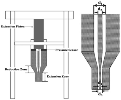
The applied pressure was to remove air voids in the mixture to obtain uniform and mechanically acceptable products. The paste extrusion setup is shown in Fig. 1. The pressure sensor (measuring range up to 80 MPa) was mounted on the extrusion piston. The reduction ratio and the speed of extrusion were 350 and 1.0 mm s−1, respectively. The extrusion was carried out at 30 °C. The PTFE hollow fiber membranes with different inner diameters were obtained through the paste extrusion process.
The reduction ratio is defined as:
 | (1) |
The different inner diameters of the PTFE hollow tube are listed in Table 1.
| Membrane code | Outer diameter (mm) | Inner diameter (mm) | Wall thickness (mm) | Porosity (%) | Contact angle (°) | Bubble points (kPa) |
|---|---|---|---|---|---|---|
| P-1 | 3 | 2 | 0.5 | 35.8 | 130.4 ± 2.8 | 50 |
| P-2 | 3 | 2 | 0.5 | 67.3 | 28.6 ± 3.2 | 37 |
| P-3 | 3 | 2 | 0.5 | 71.5 | 30.5 ± 3.0 | 28 |
| P-4 | 3 | 2 | 0.5 | 76.8 | 26.7 ± 2.3 | 15 |
| P-5 | 3 | 2 | 0.5 | 83.2 | 27.8 ± 1.8 | 10 |
| P-6 | 3 | 2 | 0.5 | 54.3 | 128.9 ± 2.7 | 22 |
| P-7 | 3 | 2 | 0.5 | 59.7 | 129.3 ± 2.5 | 20 |
| P-8 | 3 | 2 | 0.5 | 68.9 | 126.7 ± 3.7 | 18 |
| P-9 | 3 | 2 | 0.5 | 67.3 | 132.3 ± 2.5 | 12 |
| P-10 | 4 | 1 | 1.5 | 75.4 | 128.6 ± 3.1 | 17 |
| P-11 | 4 | 1.5 | 1.25 | 78.8 | 126.5 ± 3.5 | 15 |
| P-12 | 4 | 2 | 1 | 80.3 | 128.4 ± 2.3 | 16 |
| P-13 | 4 | 2.5 | 0.75 | 76.7 | 130.4 ± 1.5 | 15 |
| P-14 | 4 | 3 | 0.5 | 77.5 | 130.5 ± 2.2 | 18 |
Here, d1 is the outer diameter of the PTFE cylindrical billet, d2 is the inner diameter of the PTFE cylindrical billet, d3 is the outer diameter of the PTFE hollow tube, and d4 is the inner diameter of the PTFE hollow tube.
 | (2) |
Here, Ls is the length of the stretched PTFE hollow fiber membrane and Lo is the original length of the PTFE hollow tube before stretching. The stretching setup is shown in Fig. 2. After the stretching process, the stretched PTFE hollow fiber membrane was sintered by heating system to ensure its strength and dimensional stability. The heating temperatures were 300 °C, 340 °C, 360 °C, 380 °C, 410 °C, respectively. The heating duration was 60 s.
The stretching ratios and heating temperatures for the PTFE hollow fiber membranes preparation are listed in Table 2.
| Membrane code | Stretching ratio (%) | Stretching temperature (°C) | Heating temperature (°C) | Heating time (s) |
|---|---|---|---|---|
| P-1 | 170 | 200 | 380 | 60 |
| P-2 | 260 | 200 | 380 | 60 |
| P-3 | 330 | 200 | 380 | 60 |
| P-4 | 450 | 200 | 380 | 60 |
| P-5 | 650 | 200 | 380 | 60 |
| P-6 | 450 | 200 | 300 | 60 |
| P-7 | 450 | 200 | 340 | 60 |
| P-8 | 450 | 200 | 360 | 60 |
| P-9 | 450 | 200 | 410 | 60 |
| P-10 | 450 | 200 | 380 | 60 |
| P-11 | 450 | 200 | 380 | 60 |
| P-12 | 450 | 200 | 380 | 60 |
| P-13 | 450 | 200 | 380 | 60 |
| P-14 | 450 | 200 | 380 | 60 |
2.2 Morphology of PTFE hollow fiber membrane
The morphologies of PTFE hollow fiber membranes were investigated with a FESEM equipped with an X-ray energy dispersive spectrometer (EDS) (EVO MA 25, ZEISS, Germany). The hollow fiber membranes were frozen in liquid nitrogen, fractured to obtain fragments, and sputtered with platinum using a HITACHI E-1010 Ion Sputtering device for FESEM observation.2.3 Porosity and pore size distribution
The overall porosity was usually determined by the gravimetric method, determining the weight of liquid contained in the membrane pores. The porosity ε of the PTFE hollow fiber membrane was calculated by the following equation:44
 | (3) |
Here, m1 is the weight of the wet PTFE hollow fiber membrane, m2 is the weight of the dry PTFE hollow fiber membrane, m3 is the weight of liquid in the lumen of hollow fiber, ρL is the liquid density, l is the hollow fiber length, r1 and r2 are the outer radius and the inner radius of the hollow fiber, respectively. The weight of the liquid in the lumen was calculated by the following equation:
| m3 = ρL × V = ρL × π × r22 × l | (4) |
Here, ρL is the liquid density, r2 is the inner radius of the hollow fiber, l means the hollow fiber length, respectively. The liquid (GQ-16) used for porosity measurement was the aqueous perfluoro octane sulfopropyl betaine solution (1 wt%). It was supplied by GaoQFunc. Mater. Tech. Co. Ltd. (China) and its surface tension and density were 16 dyn cm−1 and 1.87 g ml−1, respectively. The pore size distribution of the PTFE hollow fiber membranes was investigated by using a Capillary Flow Porometer (Porometer 3GZH QantachromeInstruments, USA). The hollow fiber membranes were fully wetted with the Gq16, and then the measurements were carried out following the procedure described in the literature.45 The bubble point and pore size distribution were determined with the aid of the computer software coupled to the capillary flow porometer.
2.4 Contact angle
The contact angle measurements were performed using a tensiometer (DCAT21 Dataphysics, Germany) to determine the hydrophobic properties of the PTFE hollow fibers.46 Five specimens were tested for each hollow fiber membrane sample.2.5 Mechanical properties test
Mechanical properties of the fabricated PTFE hollow fiber membranes were investigated by measurements with an Instron tensiometer (Instron 5565-51cN, Instron Corporation, USA) at 25 °C and 65% RH. The sample was clamped at both ends and pulled in tension at a constant elongation rate of 200 mm min−1 with an initial length of 10 cm; five specimens were tested for each hollow fiber sample.2.6 Filtration performance of PTFE hollow fiber membranes
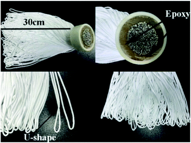
PTFE hollow fiber modules were prepared to evaluate the filtration performance of PTFE hollow fiber membranes. Both ends of hollow fibers were put on one module using epoxy and cured at room temperature. All hollow fibers present a U-shaped arrangement as shown in Fig. 3. The effective length of hollow fibers was 30 cm.The air filtration performance of PTFE hollow fibers was evaluated in a glass chamber as shown in Fig. 4, including an aerosol generation system, a hollow fiber module, and a particle detection system. The nano aerosol particles were formed by burning incense sticks. The filtration was conducted at an outside-in mode with a dead-end configuration.
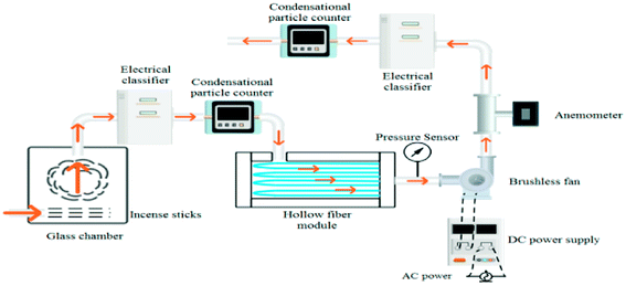 | ||
| Fig. 4 Schematic diagram of the experimental setup for a particulate generation, filtration, and measurement system. | ||
For air filtration materials or air filtration units, filtration efficiency and pressure drop are two important indicators. The air filtration is the ability of a filter unit to remove particles from an air stream and the pressure drop describes the energy requirements.
The air before and after the hollow fiber membranes was sampled, and the filtration efficiency of the membrane filter was determined using a TSI SMPS 3080 electrostatic classifier connect to a CPC 3775 particle counter with a scanning time of 45 s and a retrace time of 15 s.
| η = (C0 − C)/C0 | (5) |
The downstream side of the hollow fiber membranes was provided with a ventilator and a differential pressure sensor. Adjusting the speed of the ventilator can obtain different dead-end pressure drops. The pipeline was provided with a velocity probe to measure the flow rate and calculate the flow of fresh air.
| Q = S × V | (6) |
The flow of unit membrane area was used to evaluate the permeability of the membrane, and it was defined as follows:
 | (7) |
We copied the method of testing the air permeability in the textile field to judge the resistance of the membranes by comparing the volume of the fresh air under the same dead-end pressure drop.
2.7 Regeneration strategies for fouled membrane
After the PTFE hollow fiber membranes were applied for air filtration, several physical methods were used to clean the fouled membranes, including air back purge, water backwash, and water rinsing. To examine the efficacy of these physical methods, the flow of fresh air was compared with that produced by the new module at the same dead-end pressure.
 | (8) |
3. Result and discussion
3.1 Membrane morphology
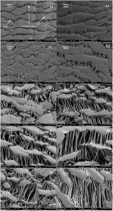
The FESEM images of the PTFE hollow fiber membranes with different stretching ratios were shown in Fig. 5. It could be seen that all the PTFE hollow fiber membranes had microstructures of nodes interconnected by fibrils. In the uniaxially stretched PTFE hollow fiber membranes, the fibrils and nodes appeared in turn regularly in spaces along the stretching direction. With the increase of stretching ratio, the areas of nodes reduced and the fibrils were elongated and densely distributed in the direction parallel to stretching direction. A higher stretching ratio tended to result in larger pore size.The microstructure of the PTFE porous membranes was made of two domains. One was the node and the other was the fibril. Node was the solid agglomerates of particles and fibrils bridged the two adjoining notes. The length of fibril increased with the increase of stretching ratio and stretching operation brought about the steady formation of fibrils and large pore size.
It was noticed that the pore sizes in the inner surface were larger than in the outer surface for all the PTFE hollow fiber membranes, which might be due to the reduction ratio. In the preforming process, the outer diameter and the inner diameter of the obtained PTFE cylindrical billet were 43.6 mm and 6.0 mm. After the paste extrusion, the outer diameter and inner diameter of the obtained PTFE hollow tube were 3 mm and 2 mm, respectively. A high reduction ratio resulted in a higher extrusion pressure on the outer surface than that on the inner surface of the PTFE hollow tube. The outer surface of the PTFE hollow tube became denser than the inner surface. Therefore, the outer surface was more difficultly stretched during the stretching process.
3.2 Pore size distribution, bubble point and porosity
The mean pore size distribution of the PTFE hollow fiber membrane was presented in Fig. 6.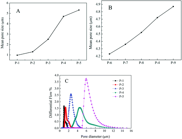 | ||
| Fig. 6 The mean pore size of the PTFE hollow fiber membrane with different (A) stretching ratios, (B) different heating temperature and (C) the pore size distribution of the hollow fiber membranes. | ||
It could be found that the pore sizes of the PTFE hollow fiber membranes became larger with the increase of stretching ratio, which was in agreement with the results of FESEM. The pore size distribution of the hollow fiber membrane was presented in Fig. 6C. In can be found that the pore sizes of the PTFE hollow fiber membranes increased with the increase of stretching ratio, which was in agreement with the analysis of membrane morphology. When the stretching ratio was 170%, the pore size distribution of the PTFE hollow fiber membrane was narrow. Larger pore size and broader pore size distribution could be acquired with a higher stretching ratio. The porosities and the bubble point of the PTFE hollow fiber membranes were presented in Table 1. The increasing stretching ratio was positive for porosity but negative for the bubble point pressure. This might be due to the fact that the pore sizes of the PTFE hollow fiber membranes became larger as the stretching ratio in the uniaxially stretching process.
It could be found that with the rise of the heating temperature, the pore size and porosity increased and the bubble point decreased. Some fibrils in the membrane break at a higher heating temperature in the heating process, which resulted in the above phenomenon.
The membranes with different inner diameters had similar mean pore size are shown in Table 3. This proved that the stretching ratio played a decisive role in the pore size of the membrane.
| Membrane code | Mean pore size (μm) | Breaking strength (MPa) | Elongation-at-break (%) |
|---|---|---|---|
| P-10 | 4.67 | 18.54 ± 0.27 | 68 ± 2 |
| P-11 | 4.75 | 17.73 ± 0.73 | 62 ± 3 |
| P-12 | 4.71 | 16.36 ± 0.58 | 58 ± 1 |
| P-13 | 4.68 | 14.67 ± 1.67 | 56 ± 3 |
| P-14 | 4.72 | 14.32 ± 0.32 | 52 ± 2 |
3.3 Contact angle
The results of contact angles in Table 1 confirmed that the PTFE hollow fiber membranes possessed the excellent hydrophobic properties. It could be seen that heating temperature and stretching ratio have little influence on the contact angle. Due to the hydrophobic properties, it was possible to clean the fouled membranes.3.4 Mechanical properties
The effect of stretching ratio and heating temperature on tensile strength was shown in Fig. 7. The stress–strain curves were shown in Fig. 7A. It could be seen that the breaking strength and elongation-at-break of the PTFE hollow fibers membranes decreased with the increase of stretching ratio. The results were mainly due to that with the increase of stretching ratio, the fibrils in the microstructure became longer in the PTFE hollow fiber membranes and easily broken in the stretching process. The tensile strength increases with the rise in heat treatment temperature. The result shown in Fig. 7B suggested that at a higher temperature some changes in the membrane structure which brought about the increase in tensile strength. It also could be seen from Table 3 that with the increase of the wall thickness of the hollow fiber membrane, the tensile strength and elongation-at-break increased.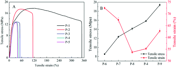 | ||
| Fig. 7 Stress–strain curves of the PTFE hollow fiber membranes with different stretching ratios (A) and mechanical properties of the PTFE hollow fiber membrane with different heating temperature (B). | ||
3.5 Air purification tests
The filtration efficiency as a function of different stretching ratios of the PTFE hollow fiber membranes was shown in Fig. 8. Clearly, the PTFE hollow fiber membrane with different stretching ratios had achieved an ultrahigh particle removal efficiency of over 99.99% for particles larger than 2.5 μm and over 90% for particles larger than 0.3 μm. The filtration efficiency of the P-4 was higher than other hollow fibers. The filtration efficiency and the flow rate across the membrane increased when the stretching ratio rose from 1.7 times to 4.5 times. Interestingly, this trend was opposite to those findings using flat symmetric porous filters where a smaller pore size lead to higher filtration efficiency and using flat symmetric fibrous filters where a higher flow rate lead to lower filtration efficiency. The PTFE hollow fiber membranes possessed the synergistic advantages of porous filters and fibrous filters with a sieve-like outer surface and a fibrous-like porous substrate. The cross-section of the PTFE hollow fiber membranes had an asymmetric structure. Due to the asymmetric structure, the high flow rate could increase the possibility of particles deposition via direct impaction and Brownian motion. For the filtration efficiency of asymmetric hollow fiber membranes, the flow rate was more important than the pore size and porosity. The filtration efficiency of P-5 reduces slightly because the larger pore size and porosity could increase the penetration of the particles.
The FESEM images of the non-heated membrane (A) and the heated membranes obtained at different temperatures: 300 °C (B), 340 °C (C), 360 °C (D), 380 °C (E), 410 °C (F). These FESEM images showed the boundary region between the fibril domain and the node. As can be seen in Fig. 9A, some PTFE particulates starting materials adhere in the node. The FESEM images of the membranes heat treated at 300 °C (B) and 340 °C (C) were similar to that of the non-heated membrane. However, the microstructure hardly changed and the PTFE particles were almost completely lost when the heat treatment temperature was up to 360 °C (D). These results suggest that the change in the microstructure observed at 360 °C was due to the melting of PTFE particles, and furthermore, it was suggested that the increase in tensile strength of the PTFE hollow fiber membrane caused at 360 °C was related to this melting of PTFE.
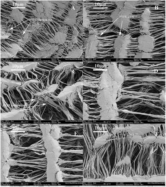 | ||
| Fig. 9 FESEM images of the PTFE hollow fiber membrane: (A) nonheated; (B) 300 °C; (C) 340 °C; (D) 360 °C; (E) 380 °C; (F) 410 °C. | ||
The filtration performance of the hollow fiber membrane with different heating temperature under the dead-end mode at the same dead-up pressure (300 Pa) after two hours of filtration was shown in Fig. 10. The fresh air volume increased with the increase of heating temperature, which might result from the pore size and the porosity. It could be seen from Fig. 6B and Table 1 that the pore size and porosity increased with the rise of heating temperature. Because in the heating process, some fibrils in the membrane break at higher heating temperature, which resulted in the increase of pore size and porosity.
We also compared the filtration efficiencies of the PTFE hollow fiber membranes with different heating temperature. It was shown that the removal efficiencies of both PM2.5 and PM0.3 were better with the heating temperature at 380 °C. The filtration efficiency crossed the membrane increase when the heating temperature raised from 300 °C to 410 °C because of the larger flow rate. The filtration efficiency of P-9 reduced slightly because the larger pore size and porosity could increase the penetration of the particles. This phenomenon was consistent with the effect of stretching ratio.
Regarding filtration performance, the filtration efficiency decreased when the wall thickness decreased from 1.5 mm to 1 mm and opposite from 1 mm to 0.5 mm. We could see an expected trend for the tested hollow fiber membranes when the wall thickness decreased from 1.5 mm to 1 mm. For thicker walls, the particles could get a higher residence time to be collected by diffusion deposition. It was consistent with symmetrical fibrous filtration. As mentioned above, for the asymmetric hollow fiber membranes, the filtration efficiency should be improved with the increase of flow rate. When the wall thickness within this interval, wall thickness had more influence on filtration performance than the flow rate at the lower flow rate.
When the wall thickness was less than 1 mm, the filtration efficiency increased as the wall thickness decreased. The hollow fiber membranes with thinner walls had a high rate of penetration. For PTFE hollow fiber membrane, its asymmetric structure in the cross-section might enhance the possibility of particles deposition via direct impaction and Brownian motion. When the wall thickness was thinner, the high flow rate might be more conducive to filtration efficiency. Hence, the wall thickness and flow rate were the two important factors that affect the filtration efficiency.
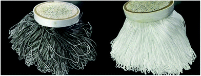
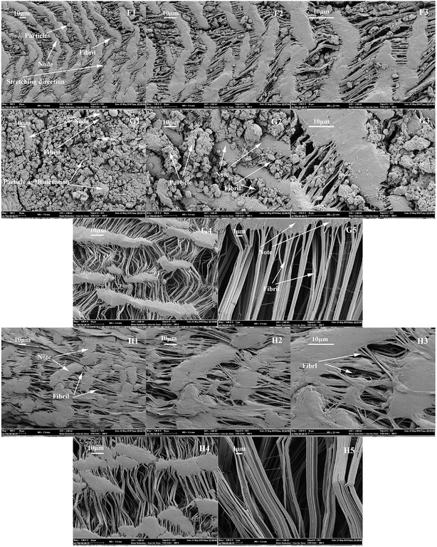
The outer surface of hollow fiber membranes after filtration was shown in Fig. 14 (F1, G1, F2, G2, F3 and G3). PTFE had the smallest surface tension in solid materials and did not adhere to any substances. The PTFE hollow fiber membranes had the microstructure of nodes interconnected by fibrils. On the surface of the membranes, some particles were captured by the pores made of fibrils. Other particles could merge to form a layer due to the air humidity. In the south of China, the humidity was high; it might increase adhesion forces among the particles and form agglomerates. Interestingly, there were few or even no particles on the surface of fibrils and notes because of the lower surface tension of the PTFE hollow fiber membranes. PTFE was often referred to as a self-cleaning material and it was a benefit to improve the repetitive-use performance of filter media.
It was clear that the larger particles might mainly intercept by the surface filtration and the smaller particles would be captured inside the hollow fiber membrane wall via the diffusion inherently. PTFE hollow fiber membranes after filtration could be cleaned by water due to the excellent hydrophobic properties.
The inner surface of the hollow fiber membrane after filtration was shown in Fig. 14 (G4 and G5). Interestingly, there were few or even no particles on the inner surface and it was not polluted. This proved that the outer surface and the wall of hollow fiber membranes played a key role in air filtration.
As shown in Fig. 14 (H1–H5), the outer and inner surface of the membrane after the swilling–drying process. This process could remove most of the particles of the outer surface and had a litter effect on the surface structure of the membrane.
The dust-holding capacity of the PTFE fiber membrane module (the area is 5 m2) in different periods of one year was shown in Fig. 15. We could divide the whole process into two stages, in the first stage, the dust holding capacity increased rapidly from the beginning to the sixth month. In this stage, dust would accumulate on the surface of the membrane like a tree branch, and the membrane had a sufficient area to hold them. But, from the sixth month to the end, the dust holding capacity increased slowly due to the limited membrane area. Dust layer had gradually appeared on the surface of the membrane and dust accumulated on the dust layer and produced a thicker dust layer in the later stage of the test. The ability of the membrane to hold dust was gradually decreasing.
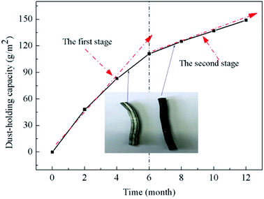 | ||
| Fig. 15 The dust-holding capacity of the PTFE fiber membrane module at different stages of one year. | ||
As shown in Fig. 16, the result evaluated as a function of time was described. Multicycle air filtration tests were conducted to investigate the long-term performance of the membrane filter within the area was 5 m2. Water-swilling was adopted in the filtration-clean cycles, after which the membranes were dried for repetitive use. The regenerated filter media were then utilized again in the next cycles and the test was taken for totally 4 cycles with 3 months for each cycle. We evaluated the performance of the PTFE hollow fiber membrane module with fresh air volume and filtration efficiency at a certain dead-end pressure (300 Pa). In each cycle, first, the fresh air volume decreased gradually because of the decrease of the pore size of the membranes caused by the particle deposition on the surface. After testing for one month in each cycle, the volume of fresh air decreased rapidly due to the quick pore blocking. To porous type filter, in addition to the above two phases, there should be a period of stability. In this period, the volume of fresh air reduced slowly result from the formation of the cake layer. This phenomenon did not occur in the PTFE hollow fiber membranes test because the filter had a capacity of dust holding and a larger area. The test time was too short to form the dense particulate layer. The end value of volume in each cycle test showed a decrease compared to the previous cycle. Perhaps, some particles were clogged on the walls of the membranes after cleaning. In contrast, the volume of fresh air exhibited a whole decrease trend with the test repeated.
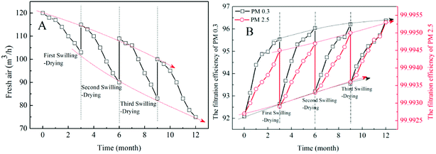 | ||
| Fig. 16 (A) Fresh air, (B) filtration efficiency of the PTFE hollow fiber membranes with 5 m2 as the function of test time. | ||
In each cycle, the filtration efficiency offered a rapid increase and remains well above 99.99% for PM2.5 and 92% for PM0.3. At the very beginning of the next cycle, the filtration efficiency dived to a low level and it was slightly higher than that at the same time in the current cycle. That was because the pore size of the membranes decreased due to the particle deposition on the surface and merge to form a layer. For HEPA in the market, three swilling and drying cycles might have a serious impact on its structure and filtration efficiency. So, for PTFE hollow fiber membrane, it had great potential as a filter in air filtration.
3.6 Comparison to other hollow fiber membranes
This study reveals as the first attempt to apply PTFE hollow fiber membranes for removing the ultrafine particles and few studies which aim to use hollow fiber membranes in air filtration. PTFE is a fluorocarbon polymer with unique characteristics. The chemical resistance, thermal stability and mechanical properties of PVDF-PEG hollow fiber membranes,43 PES hollow fiber membranes42 and PP hollow fiber membranes41 are lower than the PTFE hollow fiber membranes in this study. Due to the hydrophobicity, PTFE hollow fiber membranes have the self-cleaning ability and large dust-holding capacity of >120 g m−2 (larger than other hollow fiber membranes), slowing down membrane fouling. The fouled filter media after washing remained high filtration efficiency without obvious deterioration. There are three companies with HFM air filter products in their portfolio: KITZ Microfilter Corp. (Japan), Pisco Inc. (USA) and SMC Pneumatics Pvt. Ltd. (India). These filters are mainly used in compressed air/nitrogen and special applications such as microelectronics, print boards, precision machinery and medical equipment. Compared to PTFE hollow fiber membranes, these filters have a smaller filtration area of 80–1000 cm2, pore size of 0.01 μm and operate under low flow rates of 70–500 L min−1.4. Conclusion
The PTFE hydrophobic hollow fiber membranes were prepared for air filtration through a cold pressing method including paste extrusion, stretching and sintering. The PTFE hollow fiber membranes have the micro-structures of nodes interconnected by fibrils. The pore size and porosity are increased with an increase of stretching ratio and heating temperature. An enhancement in heating temperature and inner diameter increase the tensile strength of the membrane. The air filtration performance of PTFE hollow fiber membranes was investigated. Due to their high efficiency of PM2.5 and hydrophobic, the PTFE hollow fiber membrane may be used for air filtration. The PTFE hollow fiber membranes with different pore size, porosity and inner diameter have achieved an ultrahigh particle removal efficiency of over 99.99% for PM2.5 and over 90% for PM0.3. The thick wall thickness and the high flow rate are beneficial to improve the filtration for PTFE hollow fiber membranes. The PTFE hollow fiber membrane has a long service life and maintains good permeability after prolonged use. The membranes maintain high filtration performance after multiple swilling–drying processes.Conflicts of interest
There are no conflicts to declare.Acknowledgements
This work was supported by the National Natural Science Foundation of China [grant no. 21406207 and 21706238]; Key Laboratory of Advanced Textile Materials and Manufacturing Technology (Zhejiang Sci-Tech University), Ministry of Education (2016QN03), the Excellent Postgraduate Thesis Program of Zhejiang Sci-Tech University (grant no. 2018-XWLWPY-B-03-07, 2018-XWLWPY-M-03-06)Reference
- J. S. Apte, J. D. Marshall, A. J. Cohen and M. Brauer, Addressing Global Mortality from Ambient PM2.5, Environ. Sci. Technol., 2015, 49(13), 8057–8066 CrossRef CAS PubMed.
- R. Esworthy in Air Quality: EPA's 2013 Changes to the Particulate Matter (PM) Standard, Congressional Research Service Reports, 2015 Search PubMed.
- R. J. Huang, Y. Zhang, C. Bozzetti, K. F. Ho, J. J. Cao, Y. Han, K. R. Daellenbach, J. G. Slowik, S. M. Platt and F. Canonaco, High secondary aerosol contribution to particulate pollution during haze events in China, Nature, 2014, 514(7521), 218–222 CrossRef CAS PubMed.
- R. Betha, S. N. Behera and R. Balasubramanian, 2013 Southeast Asian smoke haze: fractionation of particulate-bound elements and associated health risk, Environ. Sci. Technol., 2014, 48(8), 4327–4335 CrossRef CAS PubMed.
- A. Nel, Atmosphere. Air pollution-related illness: effects of particles, Science, 2005, 308(5723), 804–806 CrossRef CAS PubMed.
- T. Fedel, Air filtration: Evaluating filtration efficiency, Filtr. Sep., 2012, 49(6), 37–39 CrossRef.
- N. Bruce, R. Perezpadilla and R. Albalak, Indoor air pollution in developing countries: a major environmental and public health challenge, Bull. W. H. O., 2000, 78(9), 1078–1092 CAS.
- P. Sheehan, E. Cheng, A. English and F. Sun, China's response to the air pollution shock, Nat. Clim. Change, 2014, 4(5), 306–309 CrossRef.
- M. Faccini, C. Vaquero and D. Amantia, Development of Protective Clothing against Nanoparticle Based on Electrospun Nanofibers, J. Nanomater., 2012, 2012, 18 Search PubMed.
- V. Thavasi, G. Singh and S. Ramakrishna, Electrospun nanofibers in energy and environmental applications, Energy Environ. Sci., 2008, 1(2), 205–221 RSC.
- W. J. Fisk, Health benefits of particle filtration, Indoor Air, 2014, 23(5), 357–368 CrossRef PubMed.
- R. Goyal and P. Kumar, Indoor–outdoor concentrations of particulate matter in nine microenvironments of a mix-use commercial building in megacity Delhi, Air Qual., Atmos. Health, 2013, 6(4), 747–757 CrossRef CAS.
- D. G. Karottki, M. Spilak, M. Frederiksen, L. Gunnarsen, E. V. Brauner, B. Kolarik, Z. J. Andersen, T. Sigsgaard, L. Barregard and B. Strandberg, An indoor air filtration study in homes of elderly: cardiovascular and respiratory effects of exposure to particulate matter, Environ. Health, 2013, 12(1), 116 CrossRef PubMed.
- J. P. Brincat, D. Sardella, A. Muscat, S. Decelis, J. N. Grima, V. Valdramidis and R. Gatt, A review of the state-of-the-art in air filtration technologies as may be applied to cold storage warehouses, Trends Food Sci. Technol., 2016, 50, 175–185 CrossRef CAS.
- Q. Yao, S. Q. Li, H. W. Xu, J. K. Zhuo and Q. Song, Studies on formation and control of combustion particulate matter in China: A review, Energy, 2009, 34(9), 1296–1309 CrossRef CAS.
- R. S. Barhate and S. Ramakrishna, Nanofibrous filtering media: Filtration problems and solutions from tiny materials, J. Membr. Sci., 2007, 296(1), 1–8 CrossRef CAS.
- P. Li, C. Wang, Y. Zhang and F. Wei, Air Filtration in the Free Molecular Flow Regime: A Review of High-Efficiency Particulate Air Filters Based on Carbon Nanotubes, Small, 2015, 10(22), 4543–4561 CrossRef PubMed.
- C. Wang and Y. Otani, Removal of Nanoparticles from Gas Streams by Fibrous Filters: A Review, Ind. Eng. Chem. Res., 2013, 52(1), 5–17 CrossRef CAS.
- R. Balgis, C. W. Kartikowati, T. Ogi, L. Gradon, B. Li, K. Seki and K. Okuyama, Synthesis and evaluation of straight and bead-free nanofibers for improved aerosol filtration, Chem. Eng. Sci., 2015, 137, 947–954 CrossRef CAS.
- L. Jing, K. Shim, C. Y. Toe, T. Fang, C. Zhao, R. Amal, K. Sun, J. H. Kim and Y. H. Ng, Electrospun Polyacrylonitrile-Ionic Liquid Nanofibers for Superior PM2.5 Capture Capacity, ACS Appl. Mater. Interfaces, 2016, 8(11), 7030 CrossRef CAS PubMed.
- K. Liu, Z. Xiao, P. Ma, J. Chen, M. Li, Q. Liu, Y. Wang and D. Wang, Large scale poly(vinyl alcohol-co-ethylene)/TiO2 hybrid nanofibrous filters with efficient fine particle filtration and repetitive-use performance, RSC Adv., 2015, 5(107), 87924–87931 RSC.
- N. Wang, A. Raza, Y. Si, J. Yu, G. Sun and B. Ding, Tortuously structured polyvinyl chloride/polyurethane fibrous membranes for high-efficiency fine particulate filtration, J. Colloid Interface Sci., 2013, 398(19), 240–246 CrossRef CAS PubMed.
- J. Xu, C. Liu, P. C. Hsu, K. Liu, R. Zhang, Y. Liu and Y. Cui, Roll-to-Roll Transfer of Electrospun Nanofiber Film for High-Efficiency Transparent Air Filter, Nano Lett., 2016, 16(2), 1270 CrossRef CAS PubMed.
- S. Zhang, H. Liu, J. Yu, W. Luo and B. Ding, Microwave structured polyamide-6 nanofiber/net membrane with embedded poly(m-phenylene isophthalamide) staple fibers for effective ultrafine particle filtration, J. Mater. Chem. A, 2016, 4(16), 6149–6157 RSC.
- Y. Zhang, S. Yuan, X. Feng, H. Li, J. Zhou and B. Wang, Preparation of Nanofibrous Metal-Organic Framework Filters for Efficient Air Pollution Control, J. Am. Chem. Soc., 2016, 138(18), 5785 CrossRef CAS PubMed.
- X. Zhao, S. Wang, X. Yin, J. Yu and B. Ding, Slip-Effect Functional Air Filter for Efficient Purification of PM2.5, Sci. Rep., 2016, 6, 35472 CrossRef CAS PubMed.
- X. H. Qin and S. Y. Wang, Electrospun nanofibers from crosslinked poly(vinyl alcohol) and its filtration efficiency, J. Appl. Polym. Sci., 2010, 109(2), 951–956 CrossRef.
- X. H. Qin and S. Y. Wang, Filtration properties of electrospinning nanofibers, J. Donghua Univ., 2010, 102(2), 1285–1290 CrossRef.
- Y. Chen, S. Zhang, S. Cao, S. Li, C. Fan, Y. Shuai, X. Cheng, J. Zhou, F. Xiao and X. Ma, Roll-to-Roll Production of Metal-Organic Framework Coatings for Particulate Matter Removal, Adv. Mater., 2017, 29(15), 1606221 CrossRef PubMed.
- S. Zhang, H. Liu, Y. Xia, Z. Li, J. Yu and B. Ding, Tailoring Mechanically Robust Poly(m-phenylene isophthalamide) Nanofiber/nets for Ultrathin High-Efficiency Air Filter, Sci. Rep., 2017, 7, 40550 CrossRef PubMed.
- N. Peng, N. Widjojo, P. Sukitpaneenit, M. M. Teoh, G. G. Lipscomb, T. S. Chung and J. Y. Lai, Evolution of polymeric hollow fibers as sustainable technologies: Past, present, and future, Prog. Polym. Sci., 2012, 37(10), 1401–1424 CrossRef CAS.
- A. Podgórski, A. Bałazy and L. Gradoń, Application of nanofibers to improve the filtration efficiency of the most penetrating aerosol particles in fibrous filters, Chem. Eng. Sci., 2006, 61(20), 6804–6815 CrossRef.
- F. Bougie, I. Iliuta and M. C. Iliuta, Absorption of CO 2 by AHPD–Pz aqueous blend in PTFE hollow fiber membrane contactors, Sep. Purif. Technol., 2014, 138, 84–91 CrossRef CAS.
- T. Miyoshi, T. P. Nguyen, T. Tsumuraya, H. Tanaka, T. Morita, H. Itokawa and T. Hashimoto, Energy reduction of a submerged membrane bioreactor using a polytetrafluoroethylene (PTFE) hollow-fiber membrane, Front. Environ. Sci. Eng., 2018, 12(3), 1 CrossRef CAS.
- H. Wang, S. Ding, H. Zhu, F. Wang, Y. Guo, H. Zhang and J. Chen, Effect of stretching ratio and heating temperature on structure and performance of PTFE hollow fiber membrane in VMD for RO brine, Sep. Purif. Technol., 2014, 126(15), 82–94 CrossRef CAS.
- H. Zhu, H. Wang, F. Wang, Y. Guo, H. Zhang and J. Chen, Preparation and properties of PTFE hollow fiber membranes for desalination through vacuum membrane distillation, J. Membr. Sci., 2013, 446(1), 145–153 CrossRef CAS.
- N. Mao, J. X. Liu, D. Q. Chang and X. Sun, Discussion of influencing factors on filtration performances of PTFE membrane filters, ACSR-Adv. Comput., 2015, 13, 2274–2281 Search PubMed.
- N. Zhang, X. Y. Jin, C. Huang and Q. F. Ke, Improved filtration properties of hydroentangled PTFE/PPS fabric filters caused by fibrillation, Indian J. Fibre Text. Res., 2017, 42(3), 278–285 Search PubMed.
- B. H. Park, S. B. Kim, Y. M. Jo and M. H. Lee, Filtration Characteristics of Fine Particulate Matters in a PTFE/Glass Composite Bag Filter, Aerosol Air Qual. Res., 2012, 12(5), 1030–1036 CrossRef.
- B. Zhao, W. F. Yong and T.-S. Chung, Haze particles removal and thermally induced membrane dehumidification system, Sep. Purif. Technol., 2017, 185, 24–32 CrossRef CAS.
- P. Bulejko, M. Dohnal, J. Pospíšil and T. Svěrák, Air filtration performance of symmetric polypropylene hollow-fibre membranes for nanoparticle removal, Sep. Purif. Technol., 2017, 197, 122–128 CrossRef.
- M. Li, Y. Feng, K. Wang, W. F. Yong, L. Yu and T. S. Chung, Novel hollow fiber air filters for the removal of ultrafine particles in PM2.5 with repetitive usage capability, Environ. Sci. Technol., 2017, 51(17), 10041–10049 CrossRef CAS PubMed.
- L. Y. Wang, W. F. Yong, L. E. Yu and T. S. Chung, Design of high efficiency PVDF-PEG hollow fibers for air filtration of ultrafine particles, J. Membr. Sci., 2017, 535, 342–349 CrossRef CAS.
- D. Hou, J. Wang, X. Sun, Z. Ji and Z. Luan, Preparation and properties of PVDF composite hollow fiber membranes for desalination through direct contact membrane distillation, J. Membr. Sci., 2012, 405–406(2), 185–200 CrossRef CAS.
- Y. W. Kai, T. S. Chung and M. Gryta, Hydrophobic PVDF hollow fiber membranes with narrow pore size distribution and ultra-thin skin for the fresh water production through membrane distillation, Chem. Eng. Sci., 2008, 63(9), 2587–2594 CrossRef.
- J. Zhang, J. D. Li, M. Duke, Z. Xie and S. Gray, Performance of asymmetric hollow fibre membranes in membrane distillation under various configurations and vacuum enhancement, J. Membr. Sci., 2010, 362(1), 517–528 CrossRef CAS.
| This journal is © The Royal Society of Chemistry 2018 |

