 Open Access Article
Boron carbide composites with highly aligned graphene nanoplatelets: light-weight and efficient electromagnetic interference shielding materials at high temperatures
Y. Q. Tan,
H. Luo,
X. S. Zhou,
S. M. Peng* and
H. B. Zhang *
*
Innovation Research Team for Advanced Ceramics, Institute of Nuclear Physics and Chemistry, China Academy of Engineering Physics, Mianyang, 621900, China. E-mail: pengshuming@caep.cn; hbzhang@caep.cn
First published on 26th November 2018
Abstract
B4C-based ceramic composites containing 0–2 vol% highly aligned graphene nanoplatelets (GNPs) are fabricated. The electromagnetic interference (EMI) shielding properties of the obtained composites are investigated at X-band (8.2–12.4 GHz) frequency range from room-temperature up to 800 °C. All composites exhibit outstanding EMI shielding properties with satisfactory frequency- and thermal-stability. The shielding effectiveness (SE) of GNP/B4C composites increases monotonically with increasing GNP loading. Superior room-temperature SE close to 40 dB is achieved with only 2 vol% GNPs and high SE around 35 dB still persists at 800 °C. Considering their relatively low density, GNP/B4C composites possess a high specific shielding effectiveness (SSE) of 16 dB cm3 g−1 which is among the highest values in reported ceramic-based shielding composites. Especially, the GNP/B4C composite with 2 vol% GNPs exhibits the highest SSE/t (SSE divided by thickness) values at temperatures above 200 °C for all reported shielding composites, indicating that GNP/B4C composites belong to the most promising high-temperature shielding composites. The excellent shielding properties of GNP/B4C composites arise mainly from the high electrical conductivity, high dielectric loss and the multiple reflections by the highly aligned and large-sized GNP layers.
Introduction
The ever-growing researches on ceramic-based electromagnetic interference (EMI) shielding materials have been generally motivated by their specific applications as light-weight and highly-efficient structural EMI shielding components in modern spacecraft which are commonly exposed to thermally harsh environments.1–4 Ceramics exhibit the unique combination of excellent mechanical strength and thermal stability at high temperatures which usually cannot be achieved in traditional EMI shielding materials such as metallic or electrically conductive polymer composites. Besides, ceramics usually exhibit the merits of light weight, good corrosion resistance and high dielectric loss at high temperatures.4–7One of the biggest obstacles for common ceramics as effective structural EMI shielding materials is the relatively low shielding effectiveness (SE) which had been generally ascribed to their poor electrical conductivity.2,4,8 Similar to polymer composites,9–12 the electrical conductivity and EMI SE of ceramics could be significantly enhanced by incorporating highly conductive nano-fillers such as nano-layered Ti3SiC2,7,13 carbon fiber (Cf),14,15 carbon nanotube (CNT)16,17 and graphene.1–3 Specially, it is worth noting that composites containing two-dimensional graphene could achieve considerably high EMI SE at a much lower filler content compared to one-dimensional or three-dimensional nano-fillers,18,19 and the high SE dominantly arose from the high absorption loss.19 Yuan et al. demonstrated that graphene nanoplatelets (GNPs) are more effective in enhancing the electrical conductivity and EMI SE of polymer composites by comparing the EMI shielding properties between single-wall carbon nanotube and graphene sheet/polyaniline composites.19 It can be speculated that the two-dimensional nature and high aspect ratio of GNPs played a significant role in enhancing the shielding of EMI and the total SE could be possibly further improved by optimizing the interfaces and microstructure of ceramic composites.11,20 Self-aligned reduced graphene oxide (rGO) in epoxy composites could give rises to a remarkable EMI SE of 38 dB.20 It was recently reported that the two-dimensional nano-layered MAX phase (a class of layered ternary transition-metal carbides and nitrides with a general formula of Mn+1AXn, wherein M is an early transition metal, A is an A-group element, X is either C or N, and n varies from 1 to 3)21 Ti3AlC2 with higher aspect ratio grains and higher texture degree is more favourable for high EMI SE.22 Specially, a giant X-band (8.2–12.4 GHz) EMI SE around 92 dB was reported in well aligned MXene film which is another type of highly conductive two-dimensional materials exfoliated from MAX phases.23
In addition to the total SE, the specific SE (SSE) defined as the ratio between the total SE and the density of composite is considered as another important criterion to evaluate the EMI shielding materials especially for aerospace applications.23,24 In an effort to reduce the weights of the shielding materials, foam-structured composites were produced with the aid of expanding agents.24–26 Although ceramic-based composites could achieve high EMI SE by incorporating highly conductive nanofillers, their SSE was generally lower especially than those of conductive polymer-based composites owning to their relatively higher density. Consequently, it is of vital importance to choose suitable ceramic matrix with much lower density. Meanwhile, the chosen ceramic matrix should exhibit satisfactory mechanical properties and thermal stability, especially at high temperatures.
Boron carbide (B4C) is one of the most light-weight ceramics with a density of only 2.52 g cm−3 which is comparable to polymer matrix.27 In addition, the excellent hardness, mechanical strength and thermal stability render B4C ceramics promising candidates of high-temperature structural EMI shielding ceramic matrix.27 The semiconducting characteristic of B4C could also largely benefit the EMI shielding in comparison to other insulating ceramics.28 Accordingly, it can be expected that B4C will be one of the most suitable ceramic matrices for high-temperature EMI shielding. Our previous study has demonstrated that the room-temperature EMI SE of B4C could be significantly enhanced by adding GNPs.29 Nevertheless, the EMI shielding properties of B4C-based composites at elevated temperatures still needs to be evaluated and the underlying mechanisms for the high shielding properties needs further clarification.
In this study, B4C was chosen as the ceramic matrix with 0–2 vol% GNPs being uniformly dispersed. The electrical, dielectric and EMI shielding properties of the obtained GNP/B4C composites were systematically investigated in the temperature range from 25 to 800 °C at the frequency range of 8.2–12.4 GHz (X-band). The origins of the high EMI shielding properties were explored and related mechanisms were presented.
Experimental
Composites preparation
GNPs were purchased from Deyang Carbonene Technology Co.,Ltd. The GNPs are stacks of graphene sheets about 6–8 nm in thickness and 5–10 μm in level dimensions. GNPs were first dispersed in isopropanol and sonicated for 1 h. B4C powders (Grade HS, H. C. Starck GmbH, Germany) mixed with different amount of GNPs dispersion (0–2 vol%) and 10 vol% Ti3AlC2 powders (purity > 98%, Forsman, China) as sintering aid were homogenized by attrition milling in isopropanol media for 10 h. Afterwards, the slurry was dried and then sieved. The mixed powders were placed in a 50 mm diameter graphite die and hot-pressed in vacuum under 1900 °C for 30 min. A uniaxial pressure of 30 MPa was applied during sintering. The bulk density of the sintered samples was measured by the Archimedes' method. The microstructural characterizations of the samples were determined by scanning electron microscopy (SEM, JEOL JSM 6300) and transmission electron microscopy (TEM, JEM-2100). The crystal structure of the samples was studied by X-ray diffraction (XRD). The crystal structure refinement was carried out using the FullProf program based on a triphase system with structural models of TiB2, B4C and Al2O3. The diffraction lines were modelled by a pseudo-Voigt function convoluted with axial divergence asymmetry function and the background was modelled by a linear interpolation between a set of fixed points. The following parameters were also refined for each phase: the scale factor, the zero point of detector, the unit-cell parameters, the atomic site coordinates, and the overall displacement parameter.Evaluation of EMI properties
The room-temperature electrical conductivity was measured with four-probe (dc power supply Agilent E364×A) on samples with a dimension of 13.0 × 2.5 × 2.5 mm3 using a tubular support of alumina as holder. For EMI SE characterization, specimens with dimensions of 22.86 × 10.16 × 1.50 mm3 were cut and polished. The magnitudes of complex scattering parameters (S-parameters) that correspond to reflection (S11 or S22) and transmission (S21 or S12) in the X-band frequency were determined through wave-guide method with a vector network analyzer (Agilent N5230A). For accuracy of measurement, the device is carefully calibrated with Through-Reflect-Line (TRL) approach. The high-temperature measurement of SE was performed in a waveguide heated by an inner heater at a rate of 10°C min−1. The temperature range is 25–800 °C with a temperature span of 100 °C, and each temperature spot was stabilized for 10 min in order to ensure the accuracy of measurements.The total SE (SET) can be applied and characterized as follows:30
SET = 10![[thin space (1/6-em)]](https://www.rsc.org/images/entities/char_2009.gif) log(Pi/Pt) = −10 log(Pi/Pt) = −10![[thin space (1/6-em)]](https://www.rsc.org/images/entities/char_2009.gif) log|S12|2 log|S12|2
| (1) |
SER = −10![[thin space (1/6-em)]](https://www.rsc.org/images/entities/char_2009.gif) log(1 − |S11|2) log(1 − |S11|2)
| (2) |
SEA = −10![[thin space (1/6-em)]](https://www.rsc.org/images/entities/char_2009.gif) log(|S21|2/(1 − |S11|2)) log(|S21|2/(1 − |S11|2))
| (3) |
Results and discussion
Fig. 1 shows the XRD profiles of the obtained GNP/B4C composites with 0 and 2 vol% GNPs. Besides the main diffraction peaks corresponding to B4C, TiB2 and Al2O3 phases were also detected in all composites. The presence of TiB2 and Al2O3 phases can be ascribed to the reactions between B4C and Ti3AlC2 at high temperatures, as suggested in our previous study.31 The diffraction peak at ∼26° reveals the presence of carbon, which is related to the residual carbon from reactions between B4C and Ti3AlC2.32 The XRD refinements were performed in order to obtained the amount of different phases. The amorphous carbon the residual carbon from reactions between B4C and Ti3AlC2 was not considered during the refinement. According to the refinement results, the molar ratios of TiB2, B4C and Al2O3 phases are around 13%, 83% and 4% respectively. Table 1 summarizes the phase composition, density and electrical conductivity of various GNP/B4C composites. All composites exhibit similar density which is slightly higher than that of monolithic B4C ceramics due to the presence of TiB2. The existence of highly conductive TiB2 phase also enhances the electrical conductivity of the composites. The composites without GNPs exhibit a moderate electrical conductivity of 27 S m−1, which is higher than that of monolithic B4C ceramics.28 With the increase of GNPs loading, the electrical conductivity increases monotonically. A jump of electrical conductivity occurs at 1 vol% GNPs loading and a maximum value of 1850 S m−1 was obtained in composites with 2 vol% GNPs. The enhancement of electrical conductivity is generally ascribed to the formation of numerous conducting paths by GNPs layers and TiB2 particles.32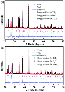 | ||
| Fig. 1 Typical XRD patterns and XRD refinements of GNP/B4C composites with (a) 0 vol% and (b) 2 vol% GNPs. | ||
| GNPs content (vol%) | Density (g cm−3) | Electrical conductivity (S m−1) |
|---|---|---|
| 0.0 | 2.63 | 27 ± 5 |
| 0.5 | 2.60 | 35 ± 4 |
| 1.0 | 2.58 | 980 ± 12 |
| 2.0 | 2.57 | 1850 ± 17 |
Fig. 2 displays the fracture surfaces of the GNP/B4C composites with different GNP loadings. All the B4C composites show dense microstructures, demonstrating the effective promotion of densification of B4C by adding Ti3AlC2. The B4C exhibits a uniform size distribution with a fine grain size around 0.5 μm. The presence of TiB2 particles can be observed in all composites, as indicated in the red circles in Fig. 2(a). The GNPs could be easily distinguished as the thin layers indicated by yellow arrows in Fig. 2(c-1) and (d-1). It can be seen that the GNPs were distributed uniformly in all GNP/B4C composites. The GNPs are more uniformly distributed compared to our previous study due to the utilization of isopropanol as dispersion media.32 Correspondingly, the electrical conductivity becomes slightly higher as demonstrated in Table 1. The level dimension of GNPs layers varies from several micrometres to tens of micrometres, which is consistent with the raw GNPs layers. GNP layers with a level dimension over 20 μm were occasionally seen as indicated in Fig. 2(d-2). The level dimension of GNPs in this study is apparently larger than most studies in literature.1–3 Accordingly, the GNP layers show certain degree of parallel alignment under high applied pressure during sintering, as demonstrated in Fig. 2(c-1) and (d-1). The large level dimensions and texture-like alignment of GNPs are highly desirable and were supposed to induce high EMI shielding efficiency for electromagnetic waves that emanate through the thickness direction.20,33 Fig. 3(a) and (b) display the TEM images of the GNP/B4C composites at lower and higher resolutions respectively. GNP was found to locate well along the grain boundaries. A simple estimate taking into account the thickness of the single graphene sheets (∼2 nm) gives a proportion of ∼30 layers of graphene in the observed GNP sheet. The relatively higher observed thickness is a consequence of two GNPs stacking closely together, as shown in Fig. 3(b).
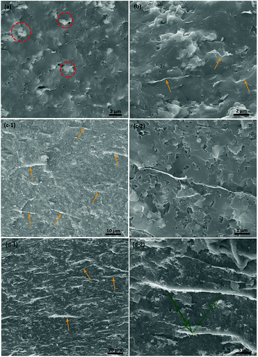 | ||
| Fig. 2 Fracture surfaces of GNP/B4C composites with different GNP loading. (a) 0 vol%; (b) 0.5 vol%; (c-1) and (c-2) 1 vol%; (d-1) and (d-2) 2 vol%. | ||
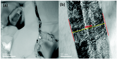 | ||
| Fig. 3 TEM images of B4C/GNP composites with 2 vol% GNPs. (a) Lower magnification; (b) higher magnification. | ||
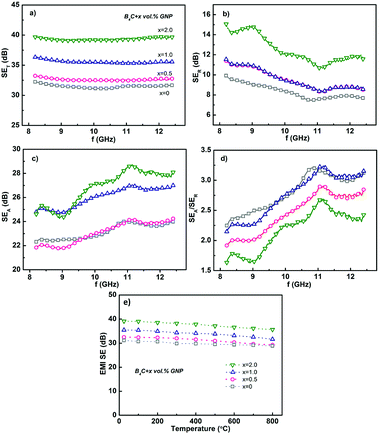
Fig. 4(a) compares the total room-temperature EMI SE (SET) of GNP/B4C composites with different GNPs content measured at the X-band frequency range. The SET of B4C composite without GNPs shows a relatively high value (∼32 dB) with a tiny variation at the measured frequency range. The high SET could be mainly attributed to the semiconducting nature of B4C matrix and the presence of highly conductive TiB2 particles. The addition of 0.5 vol% GNPs gives rise to a slight enhancement of the SET to ∼33 dB. With further increase of GNPs, SET increased remarkably and a maximum SET close to 40 dB was obtained in GNP/B4C composite with only 2 vol% GNPs which is almost the lowest amount of nano-fillers required to achieve such a high EMI SET in reported ceramic- or even polymer-based composites.1–3,7,20 Correspondingly, 99.99% of the incident EMI energy could be effectively shielded at room-temperature for GNP/B4C composite with 2 vol% GNPs. The overall EMI SET could be further divided into three parts which correspond to reflection (SER), absorption (SEA) and the multiple reflections (SEM) respectively.34 The multiple reflection effect, nevertheless, is included in the absorption because the re-reflected waves could get absorbed or dissipated within the composite material.23 Accordingly, the SET of GNP/B4C composites could be expressed as follows for simplicity,
| SET = SER + SEA | (4) |
The frequency dependences of the SER and SEA of GNP/B4C composites were exhibited in Fig. 4(b) and (c) respectively. The SER exhibits a significant enhancement when the GNPs loading is higher than 1 vol%, which is in consistency with the dependence of electrical conductivity on GNPs loading. The composite with 2 vol% GNPs shows high SER in the range of 11–15 dB. The high SER can be ascribed to the giant impedance mismatch between GNP/B4C composites and the free air. In theory, for a plane wave radiation, the far field reflection loss (SER) is given by7
SER = 39.5 + 10![[thin space (1/6-em)]](https://www.rsc.org/images/entities/char_2009.gif) log log![[thin space (1/6-em)]](https://www.rsc.org/images/entities/char_2009.gif) σ/(2πfμ) σ/(2πfμ)
| (5) |
Table 2 compares the EMI SE of various advanced ceramic composites reported in literatures.1–3,8,13–17,22,35–37 It can be observed that considerably high EMI SE over 30 dB can be achieved in many ceramic composites by incorporating highly conductive nanofillers such as Cf, CNT, GNP and Ti3AlC2 particles. More importantly, their high EMI SE could be well maintained or even enhanced at high temperatures up to 600 °C. However, the high EMI SE of most ceramic composites was achieved either by high filler loading or large thickness. Moreover, the preparation of some ceramics such as SiC/SiC composites with high SE is costly and time-consuming compared to the preparation of GNP/B4C composite in this study. It seems that only Al2O3 composites with 2 vol% GNPs exhibit similar EMI shielding properties with B4C composites in this study. However, the density of Al2O3 is much higher than B4C. Regarding the aerospace applications of EMI shielding materials, the specific EMI shielding effectiveness SSE (SE divided by density of composite) is more appropriate to judge the shielding performances of different shielding composites.23,24 Nevertheless, SSE alone is not a sufficient parameter for understanding overall effectiveness, as a higher SSE can simply be achieved at a larger thickness, which directly increases the weight of the final product. Therefore, a more realistic parameter is to divide SSE by the material thickness (SSE/t). Fig. 5 shows the temperature dependent SSE/t of various EMI shielding composites reported in literature and this study. It can be observed that metals exhibit both lower SSE/t values and lower application temperature; carbon/polymer composites show extremely high SSE/t values while lower application temperature (generally lower than 300 °C); Traditional ceramic-based composites exhibit the highest application temperature (≥400 °C) while relatively lower SSE/t values which are comparable to metals such as copper. GNP/B4C composite with 2 vol% GNPs in this study exhibits simultaneously high SSE/t values and application temperature. The high SSE/t around 100 dB cm2 g−1 were well maintained up to 800 °C. It can be concluded that GNP/B4C composite with 2 vol% GNPs in this study exhibit the highest EMI shielding efficiency both at temperatures higher than 400 °C in all EMI shielding composites investigated so far, indicating that the application of B4C/GNP composites as light-weight structural EMI shielding materials at high temperatures is highly promising.
| Matrix | Filler and loading | Thickness (mm) | Frequency range | Temperature range | EMI SE (dB) | Ref. | |
|---|---|---|---|---|---|---|---|
| RT | HT | ||||||
| a Ordered mesoporous carbon.b Pyrolytic carbon. | |||||||
| SiO2 | r-GO 20 wt% | 1.5 | X band | 25–200 °C | ∼36 | ∼37 | 3 |
| SiO2 | MWCNT 10 wt% | 2.5 | X band | 100–500 °C | ∼21 | ∼23 | 17 |
| SiO2 | Cf 20 wt% | 2.5 | X band | 25–600 °C | ∼12 | ∼12 | 15 |
| SiO2 | OMCa 10 vol% | 5.0 | X band | 25 °C | ∼40 | — | 37 |
| SiC | Cf 40 vol% | 3.0 | X band | 25 °C | ∼31 | — | 14 |
| SiCf/SiC | Ti3SiC2 14.4 wt% | 3.0 | X band | 25–600 °C | ∼20 | ∼45 | 7 |
| SiCf/SiC | PyCb 3.3 vol% | 2.0 | X band | 25 °C | ∼26 | 35 | |
| Al2O3 | GNP 2 vol% | 1.5 | X band | 25–400 °C | ∼23 | ∼37 | 2 |
| Al2O3 | Ti3SiC2 25 vol% | 1.0 | Ku-band | 25 °C | ∼32 | — | 13 |
| BaTiO3 | GNP 4 wt% | 1.5 | X band | 25 °C | ∼42 | — | 1 |
| Ti3AlC2 | — | 1.5 | X band | 25–800 °C | ∼34 | ∼31 | 7 |
| 3Y-TZP | MWCNT 9 wt% | 1.0 | Ku band | 25 °C | 25–30 | — | 8 |
| Si3N4 | PyC 11.7 vol% | 2.8 | X band | 25 °C | ∼43 | — | 36 |
| B4C | GNP 2 vol% | 1.5 | X band | 25–800 °C | ∼40 | ∼36 | |
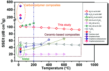 | ||
| Fig. 5 Comparison of SSE/t for typical EMI shielding materials reported in literature and this study. | ||
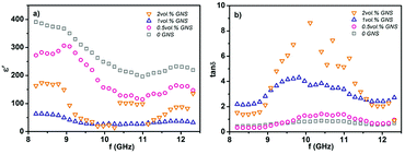
Generally, the high shielding properties of GNP/B4C composites can be attributed to the high reflection loss and absorption loss. The high reflection loss comes from the highly conductive networks formed by GNPs and TiB2. The absorption of the radiation could arise from different energy dissipation processes as ohmic loss, dielectric loss and magnetic loss.35 In GNP/B4C composites magnetic loss can be generally neglected. The ohmic loss is mainly due to the high electrical conductivity of GNP/B4C composites. Compared to ohmic loss, the dielectric loss is expected to make a dominant contribution to the high attenuation of microwave in GNP/B4C composites. Fig. 6(a) illustrates the real part of the complex permittivity of GNP/B4C composites with different GNP loadings. Composite without GNPs exhibit relatively high permittivity between 200 and 400 in the X-band frequency range and it decreases gradually with increasing frequency, which is higher than the reported values in literatures. The high permittivity of B4C composites mainly arises from the hopping electrons of B4C and free electrons in TiB2 phase. Besides, the defects produced during high-temperature sintering and reactions could also contribute to the high permittivity. With the increase of GNPs content, the real permittivity keeps decreasing to ∼50 at 1 vol% GNPs. With further increasing GNPs content, no more decrease of permittivity was observed. The significantly decreased real permittivity can be ascribed to the weaken ability to storage electrical charges by the formation of highly conductive GNPs networks in B4C composites with high GNPs loading. Being opposite to the real part of permittivity, the dielectric loss tan![[thin space (1/6-em)]](https://www.rsc.org/images/entities/char_2009.gif) δ defined as the ratio between the imaginary and the real part of the complex permittivity of GNP/B4C composites increases monotonically with increasing GNP content, as exhibited in Fig. 6(b). When the GNP content is below 1 vol%, the dielectric loss kept around 1. GNP/B4C composite with 2 vol% GNPs exhibit a highly lossy characteristic with extremely high dielectric loss between 1 and 9. The high dielectric loss of GNP/B4C composites can be ascribed to the high imaginary permittivity which was generally described as below,7
δ defined as the ratio between the imaginary and the real part of the complex permittivity of GNP/B4C composites increases monotonically with increasing GNP content, as exhibited in Fig. 6(b). When the GNP content is below 1 vol%, the dielectric loss kept around 1. GNP/B4C composite with 2 vol% GNPs exhibit a highly lossy characteristic with extremely high dielectric loss between 1 and 9. The high dielectric loss of GNP/B4C composites can be ascribed to the high imaginary permittivity which was generally described as below,7
 | (6) |
 is the electron relaxation polarization, σ is the electrical conductivity, ε0 is the dielectric constant in vacuum, and ω is the angular frequency. The first term in eqn (6) is related to the relaxation loss of microwave and arises mainly from interface polarization and defects produced during high-temperature sintering. The last term corresponds to the conductance loss resulted from the formation of conductive nanofiller networks acting as dissipating mobile charge carriers in the composites. The high conductivity gives rise to high imaginary permittivity and consequently high electromagnetic radiation dissipation. Besides the high dielectric loss, the high absorption loss of GNP/B4C composites partially arises from the presence of aligned two-dimensional nano-layered architecture.20,33 The parallel aligned GNPs layers could induce multiple reflections inside the composites. The multiple reflections prolong the EM wave propagation path and enhance the absorption accordingly. The multiple reflections are speculated to be responsible for the different EMI shielding efficiency in composites containing GNP and CNT. With increasing temperature, the dielectric loss decreased due to the lower internal friction during the rotation of the dipoles, thereby leads to a slight decrease of SET.
Conclusions
Light-weight B4C composites with high EMI shielding properties were successfully obtained by incorporating a small amount of GNPs. The composites containing only 2 vol% GNPs exhibit a high room-temperature shielding effectiveness around 40 dB and a satisfactory shielding effectiveness over 35 dB at 800 °C in the whole X-band frequency range. A high SSE/t around 100 dB cm2 g−1 which was almost the highest value reported in ceramic-based shielding composites was achieved in GNP/B4C composites containing 2 vol% GNPs. The outstanding shielding performance of GNP/B4C composites was ascribed to: (1) high reflection loss and ohmic loss due to high electrical conductivity; (2) high dielectric loss resulting from the interfacial polarization and large amounts of defects; (3) multiple reflections by parallel-aligned GNP layers.Conflicts of interest
There are no conflicts to declare.Acknowledgements
This work was supported by the National Natural Science Foundation of China (Grants No. 91326102 and 51532009), and the Science and Technology Development Foundation of China Academy of Engineering Physics (Grant No. 2013A0301012). Haibin Zhang is grateful to the foundation by the Recruitment Program of Global Youth Experts and the Youth Hundred Talents Project of Sichuan Province.Notes and references
- Y. Qing, Q. Wen, F. Luo, W. Zhou and D. Zhu, J. Mater. Chem. C, 2016, 4, 371–375 RSC.
- Y. Qing, Q. Wen, F. Luo and W. Zhou, J. Mater. Chem. C, 2016, 4, 4853–4862 RSC.
- B. Wen, M. Cao, M. Lu, W. Cao, H. Shi, J. Liu, X. Wang, H. Jin, X. Fang, W. Wang and J. Yuan, Adv. Mater., 2014, 26, 3484–3489 CrossRef CAS PubMed.
- X. Yin, L. Kong, L. Zhang, L. Cheng, N. Travitzky and P. Greil, Int. Mater. Rev., 2014, 59, 326–355 CAS.
- B. Zhang, J. Li, J. Sun, S. Zhang, H. Zhai and Z. Du, J. Eur. Ceram. Soc., 2002, 22, 93–99 CrossRef CAS.
- X. Li, L. Zhang, X. Yin, L. Feng and Q. Li, Scr. Mater., 2010, 63, 657–660 CrossRef CAS.
- Y. Mu, W. Zhou, F. Wan, D. Ding, Y. Hu and F. Luo, Composites, Part A, 2015, 77, 195–203 CrossRef CAS.
- S. Shi and L. Ji, Nanotechnology, 2008, 19, 255707 CrossRef PubMed.
- J.-M. Thomassin, C. Jérôme, T. Pardoen, C. Bailly, I. Huynen and C. Detrembleur, Mater. Sci. Eng., R, 2013, 74, 211–232 CrossRef.
- Y. Yang, M. C. Gupta, K. L. Dudley and R. W. Lawrence, Nano Lett., 2005, 5, 2131–2134 CrossRef CAS PubMed.
- D. Yan, H. Pang, B. Li, R. Vajtai, L. Xu, P. Ren, J. Wang and Z. Li, Adv. Funct. Mater., 2015, 25, 559–566 CrossRef CAS.
- M. H. Al-Saleh, W. H. Saadeh and U. Sundararaj, Carbon, 2013, 60, 146–156 CrossRef CAS.
- S. Shi, L. Zhang and J. Li, J. Appl. Phys., 2008, 103, 124103 CrossRef.
- L. Chen, X. Yin, X. Fan, M. Chen, X. Ma, L. Cheng and L. Zhang, Carbon, 2015, 95, 10–19 CrossRef CAS.
- M. Cao, W. Song, Z. Hou, B. Wen and J. Yuan, Carbon, 2010, 48, 788–796 CrossRef CAS.
- Y. Qing, Y. Mu, Y. Zhou, F. Luo, D. Zhu and W. Zhou, Eur. Ceram. Soc., J., 2014, 34, 2229–2237 CrossRef CAS.
- B. Wen, M. Cao, Z. Hou, W. Song, L. Zhang, M. Lu, H. Jin, X. Fang, W. Wang and J. Yuan, Carbon, 2013, 65, 124–139 CrossRef CAS.
- S. H. Xie, Y. Y. Liu and J. Y. Li, Appl. Phys. Lett., 2008, 92, 243121 CrossRef.
- B. Yuan, L. Yu, L. Sheng, K. An and X. Zhao, J. Phys. D: Appl. Phys., 2012, 45, 235108 CrossRef.
- N. Yousefi, X. Sun, X. Lin, X. Shen, J. Jia, B. Zhang, B. Tang, M. Chan and J.-K. Kim, Adv. Mater., 2014, 26, 5480–5487 CrossRef CAS PubMed.
- J. Wang and Y. Zhou, Annu. Rev. Mater. Res., 2009, 39, 415–443 CrossRef CAS.
- Y. Tan, H. Luo, H. Zhang, X. Zhou and S. Peng, Scr. Mater., 2017, 134, 47–51 CrossRef CAS.
- F. Shahzad, M. Alhabeb, C. B. Hatter, B. Anasori, S. Man Hong, C. M. Koo and Y. Gogotsi, Science, 2016, 353, 1137–1140 CrossRef CAS PubMed.
- Z. Chen, C. Xu, C. Ma, W. Ren and H. Cheng, Adv. Mater., 2013, 25, 1296–1300 CrossRef CAS PubMed.
- B. Shen, Y. Li, D. Yi, W. Zhai, X. Wei and W. Zheng, Carbon, 2016, 102, 154–160 CrossRef CAS.
- Y. Zhang, Y. Huang, T. Zhang, H. Chang, P. Xiao, H. Chen, Z. Huang and Y. Chen, Adv. Mater., 2015, 27, 2049–2053 CrossRef CAS PubMed.
- F. Thévenot, J. Eur. Ceram. Soc., 1990, 6, 205–225 CrossRef.
- T. L. Aselage, D. Emin and S. S. McCready, Phys. Rev. B, 2001, 64, 054302 CrossRef.
- Y. Tan, H. Luo, H. Zhang, X. Zhou and S. Peng, AIP Adv., 2016, 6, 035208 CrossRef.
- M. H. Al-Saleh and U. Sundararaj, Carbon, 2009, 47, 1738–1746 CrossRef CAS.
- Y. Tan, H. Luo, H. Zhang, X. Zhou and S. Peng, Ceram. Int., 2016, 42, 7347–7352 CrossRef CAS.
- Y. Tan, H. Luo, H. Zhang and S. Peng, J. Eur. Ceram. Soc., 2016, 36, 2679–2687 CrossRef CAS.
- B. Shen, W. Zhai and W. Zheng, Adv. Funct. Mater., 2014, 24, 4542–4548 CrossRef CAS.
- D. D. L. Chung, Carbon, 2001, 39, 279–285 CrossRef CAS.
- D. Ding, Y. Shi, Z. Wu, W. Zhou, F. Luo and J. Chen, Carbon, 2013, 60, 552–555 CrossRef CAS.
- X. Li, L. Zhang and X. Yin, J. Eur. Ceram. Soc., 2013, 33, 647–651 CrossRef CAS.
- J. Wang, C. Xiang, Q. Liu, Y. Pan and J. Guo, Adv. Funct. Mater., 2008, 18, 2995–3002 CrossRef CAS.
| This journal is © The Royal Society of Chemistry 2018 |

