 Open Access Article
3D web freestanding RuO2–Co3O4 nanowires on Ni foam as highly efficient cathode catalysts for Li–O2 batteries†
Zhuo-Liang Jiang‡
,
Jing Xie‡,
Cong-Shan Luo,
Meng-Yang Gao,
Huan-Liang Guo,
Mo-Han Wei,
Hong-Jun Zhou and
Hui Sun *
*
State Key Laboratory of Heavy Oil Processing, Beijing Key Laboratory of Biogas Upgrading Utilization, Institute of New Energy, China University of Petroleum-Beijing, Beijing, 102249, China. E-mail: sunhui@cup.edu.cn
First published on 27th June 2018
Abstract
The mechanism of Li–O2 batteries is based on the reactions of lithium ions and oxygen, which hold a theoretical higher energy density of approximately 3500 W h kg−1. In order to improve the practical specific capacity and cycling performance of Li–O2 batteries, a catalytically active mechanically robust air cathode is required. In this work, we synthesized a freestanding catalytic cathode with RuO2 decorated 3D web Co3O4 nanowires on nickel foam. When the specific capacity was limited at 500 mA h g−1, the RuO2–Co3O4/NiF had a stable cycling life of up to 122 times. The outstanding performance can be primarily attributed to the robust freestanding Co3O4 nanowires with RuO2 loading. The unique 3D web nanowire structure provides a large surface for Li2O2 growth and RuO2 nanoparticle loading, and the RuO2 nanoparticles help to promote the round trip deposition and decomposition of Li2O2, therefore enhancing the cycling behavior. This result indicates the superiority of RuO2–Co3O4/NiF as a freestanding highly efficient catalytic cathode for Li–O2 batteries.
Introduction
As a favorable solution to the energy shortage and environmental crisis, electric vehicles (EVs) are gaining more and more attention. Almost all EVs are Li-ion battery-driven and achieve unsatisfactory mileage due to the limited energy density of Li-ion batteries.1 With a high theoretical energy density of approximately 3500 W h kg−1, Li–O2 batteries (LOBs) could be the leader for use in EVs.2–4 The mechanism of LOBs is based on a simple series of reactions between lithium ions and oxygen, namely, oxygen reduction reactions (ORRs) and oxygen evolution reactions (OERs).5–7 In the discharge process the ORR happens, where oxygen is reduced to form Li2O2 with the lithium ions from the electrolyte,8 while the OER happens in the charge process, when the Li2O2 electrochemically decomposes to oxygen and lithium ions. Despite their high performance, they still have many disadvantages, such as poor cycling ability, high charging voltages, low energy efficiency and poor electrolyte stability, as well as cathode stability in the cell environment.9–11In traditional LOBs, carbonaceous materials and organic binders have been used to compose a typical oxygen cathode.12,13 However, the use of carbon materials and a binder to cover the surface of cathodes results in tough challenges, such as the resulting high polarization and poor cycle life and limited conductivity.14–16 In addition, because of the low solubility of the discharge product Li2O2 in organic electrolyte, any undecomposed Li2O2 can block the path of oxygen diffusion, leading to electrode degradation.17 Accordingly, the ideal electrode should contain a porous structure and bifunctional catalysts with excellent ORR and OER performance.18–20 Among the many investigated binder-free oxygen cathodes, the use of commercial nickel foam (NiF), which is widely used as a substrate due to its good electron conductivity and 3D porous structure, is beneficial for Li2O2 deposition and electron transferability.21–24
Catalysts when used as important cathode materials can effectively lower the overpotential and enhance the cycling stability of Li–O2 batteries. Transition metal oxide catalysts and noble metal oxide catalysts are widely used. Cobalt oxide-based catalysts, for example, such as the widely studied compound Co3O4, can serve as good bifunctional catalysts for Li–O2 batteries due to their low cost, high redox activity and favorable catalytic activity for both ORR and OER.25–28 Cui et al. first reported free-standing Co3O4 arrays growing on the surface of NiF that showed a low polarization and a relative high capacity of 1880 mA h g−1.29 However, the cycling stability of the material was limited to only 5 cycles due to the use of propylene carbonate electrolyte, which is known to be unsuitable for the long-term operation of Li–O2 cells.30 Lee et al. synthesized Co3O4 nanowire (NW) arrays vertically grown on NiF and demonstrated that this type of morphology is restrained by the decomposition of Li2O2.31 He et al. synthesized Co3O4 rectangular nanosheets that led to a higher specific capacity of 1380 mA h g−1 and better cycling stability over 54 cycles at a fixed current density of 100 mA g−1.32
Normally, freestanding oxide arrays grown on substrates are usually well structured but have poor catalytic activity. Many studies have found that the catalytic performance of pristine freestanding arrays could be markedly improved after the loading of noble metals/oxides. Many precious metals/oxides such as Pt,33 Pd,34 Ag,35 Au36 and Ru/RuO2,37–42 have been used in LOBs. Among these noble metals, Ru and RuO2 have attracted great interest due to their excellent catalytic activity, which dramatically reduces the charging overpotential and improves the round-trip efficiency.20 Liao et al. successfully grew nanoporous Ru on NiF via a galvanic replacement reaction and showed that this material has a voltage window of 2.75–3.75 V with a limited capacity of 1000 mA h g−1.43 Liu et al. reported a Ru nanoparticle decorated carbon-free O2 cathode using 3D ultralight porous nickel which demonstrated a relatively high specific capacity of 2410 mA h g−1 at a limited current density of 150 mA g−1.44 However, if too much of the noble metal is used, the cost of the material will be too high for commercial use in EVs. To produce a low-cost cathode catalyst, it is necessary to reduce the noble metal content in the battery whilst maintaining a high catalytic performance.
In this work, we synthesized Co3O4 nanowires directly on nickel foam using a two-step hydrothermal and heat treatment preparation. Then, RuO2 nanoparticles were decorated on the Co3O4/NiF using immersion methods to produce a cathode for use in Li–O2 batteries, resulting in enhanced catalytic activity due to the freestanding structure and RuO2 loading. Therefore, compared with LOBs with a Co3O4 cathode, the ones with a RuO2–Co3O4 cathode exhibited a much more improved electrochemical performance with a durable cycling stability of 122 cycles at a limited capacity of 500 mA h g−1.
Experimental section
Electrode preparation
Analytical grade chemicals were purchased and used without any further purification. Nickel foam was cut into 2 cm × 5 cm pieces and then cleaned in acetone and ethanol for half an hour. After tailoring, the pretreated pieces were dried in an oven overnight and weighed before use, and the weight was recorded as m1. In a typical synthesis of the Co3O4 nanowires, 2 mmol of Co(NO3)2 and 3 mmol of (NH4)2SO4 were weighed and mixed in 80 ml of deionized (DI) water under magnetic stirring for 10 min. Then 10 mmol of urea was dissolved in another 20 ml of DI water and stirred for 10 min. After that, the latter solution was slowly dropped into the former pink solution followed by a further 20 min of stirring. Then, pretreated nickel foam combined with the precursor solution was transferred into a Teflon-lined stainless autoclave. The autoclave was sealed and put into an electric oven and heated at 120 °C for 8 h. In order to remove the redundant particles, the products were removed from the autoclave and rinsed more than 3 times with ultrapure water and anhydrous alcohol. Ni-supported Co3O4 nanowires were finally obtained after heating at 300 °C for 2 h in air, after which the Co3O4/NiF was weighed again, and the weight was recorded as m2. To prepare RuO2–Co3O4 nanowires, the previously synthesized materials were steeped in a RuCl3 aqueous solution (3 mg l−1) for 1 h, followed by drying at 60 °C for 6 h and annealing at 300 °C for 2 h in Air. RuO2–Co3O4/NiF was weighed, and the weight was recorded as m3. The loading masses of RuO2–Co3O4 and Co3O4 are based on the difference between m3 and m1 as well as the difference between m2 and m1, respectively. The loading mass of RuO2–Co3O4 on Ni foam was found to be approximately 0.8 mg cm−2. According to the energy dispersive X-ray spectroscopic (EDS) results, the weight percentage of RuO2 in RuO2–Co3O4 is around 2.5% (Fig. S1†). The Ru–Co3O4/NiF cathode was synthesized by following a literature procedure.38Electrode characterization
The nanowires grown on the NiF were scraped off and examined using powder X-ray diffraction (PXRD) on a Bruker D8 advance powder diffractometer with Cu Kα radiation operating at 40 keV. X-ray photoelectron spectroscopic (XPS) studies were conducted with an ESCALAB MARK II spherical analyser using a magnesium anode (Mg 1253.6 eV) X-ray source. The morphologies of the air electrodes (or nanowires grown on NiF) were observed using a scanning electron microscope (SEM, Quanta 200F) fitted with an energy dispersive X-ray spectrometer (EDS) operating at 15 kV. Transmission electron microscopy (TEM) was carried out using a JEM 2100 LaB6 microscope. RuO2–Co3O4/NiF was immersed in absolute ethanol and sonicated for 30 min, after which the solution was dropped onto holey carbon-coated Cu grids. The discharge products were characterized by Raman spectroscopy (JOBIN YVON Technology, Horiba LabRAM HR Evolution) at a 532 nm excitation wavelength in the range of 100–1000 cm−1.Electrochemical measurements
The electrochemical properties of the non-aqueous Li–O2 batteries were measured on top-holed CR2032-type coin cells. The non-aqueous Li–O2 batteries were assembled in an argon-filled glove box with less than 0.5 ppm water and oxygen content. The as-prepared RuO2–Co3O4/NiF was tailored (0.7 cm × 0.7 cm) and used as the cathode. Li metal foil was used as the anode and a glass fiber membrane (Whatman GF/D) was chosen as the separator. The electrolyte used was 1 M LiTFSI (Aladdin) in tetraethylene glycol dimethyl ether (TEGDME, Aladdin). The catalytic cathodes were dried in an oven at 80 °C for more than 6 h before use to eliminate the influence of water. After assembly, the cells were sealed in a vessel filled with high-purity oxygen. The cells were galvanostatically charged and discharged after 5 h of rest on a battery test system (LAND-V34, Land Electronic Co. Ltd, Wuhan) at room temperature. The cell performance evaluations (current density and specific capacity) of the RuO2–Co3O4 electrodes were calculated based on the total weight of Co3O4 and RuO2, and those of the bare Co3O4 electrodes were based on the weight of Co3O4. Cyclic voltammetry (CV) measurements were conducted on an electrochemical workstation (AMETEK Solartron 1260/1287) within a potential range of 2.0–4.3 V at a scan rate of 0.1 mV s−1. Electrochemical impedance spectroscopic (EIS) measurements were taken at the initial state, 1st-discharged state and 1st-charged state at a fixed specific capacity of 500 mA h g−1. The AC voltage was 10 mV in amplitude and the frequency range used was between 10 mHz and 100 kHz.Results and discussion
3D web Co3O4 nanowires grown on Ni foam (Co3O4/NiF) were synthesized through a mild hydrothermal route followed by annealing of the material in an air atmosphere. RuO2–Co3O4 nanowires were prepared by simply steeping Co3O4/NiF in a RuCl3 aqueous solution, followed by annealing in an air atmosphere. The crystal structure of the as-prepared RuO2–Co3O4/NiF was characterized by powder X-ray diffraction (PXRD), as shown in Fig. 1a, using RuO2–Co3O4 exfoliated from RuO2–Co3O4/NiF. All of the diffraction peaks correspond to crystalline Co3O4 (PDF # 42-1467). There is no obvious peak for RuO2 due to the small loading amount. X-ray photoelectron spectroscopy (XPS) was used to study the oxidation state of RuO2–Co3O4 (Fig. 1b and c). The XPS spectrum of Co 2p, as shown in Fig. 1b, consists of two primary peaks with binding energies of 779.8 and 795.0 eV,44,45 which were assigned to Co 2p3/2 and 2p1/2, respectively. The 15.2 eV spin-energy separation of the two binding energies is a feature of Co3O4.46 The small peaks observed at 788.20 and 805.20 eV close to the main peaks are common satellite peaks. The binding energies of Ru 3p3/2 and 3p1/2 in RuO2–Co3O4 can be observed at 462.2 eV and 486.9 eV, respectively (Fig. 1c),8,47 and were assigned as Ru(IV) species. The PXRD and XPS results confirmed the formation of RuO2–Co3O4 on the Ni foam.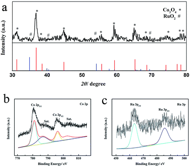 | ||
| Fig. 1 (a) PXRD patterns of RuO2–Co3O4 exfoliated from the Ni foam, (b) Co 2p XPS spectrum and (c) Ru 3p XPS spectrum of RuO2–Co3O4 on Ni foam. | ||
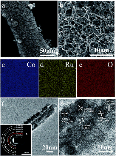
Scanning electron microscopy (SEM) and transmission electron microscopy (TEM) were used to further study the morphology and structure of the as-prepared RuO2–Co3O4/NiF cathode. The SEM images of RuO2–Co3O4/NiF (Fig. 2a) show the nanowires growing on the surface of the Ni foam, presenting a 3D web-like morphology. Fig. 2b shows a magnified SEM image where the nanowires are evenly distributed and randomly leaning on the Ni foam with a porous structure. It is noted that this morphology is the same as that without RuO2 nanoparticle loading (the morphology of Co3O4/NiF is shown in Fig. S2†). The distance between each nanowire is measured as ca. 1 μm and could allow for the transportation of O2 or electrolyte. The architecture of the catalyst-cathode is of paramount importance for Li–O2 cells, since the cathode should provide enough channels for the transportation of Li+ ions or oxygen and guarantee enough space for the deposition of discharge products from the electrochemical reactions. Fig. 2c–e show the elemental mapping of Fig. 2a (the as-prepared RuO2–Co3O4/NiF cathode). It is easy to observe that Co and Ru are uniformly distributed on the surface of NiF, which might be beneficial for both the ORR and OER processes in Li–O2 cells. The energy dispersive spectrometer (EDS) results of RuO2–Co3O4 reveal that only a small amount of RuO2 is loaded on the Co3O4 nanowires and that the weight percentage of RuO2 in RuO2–Co3O4 is 2.4% (Fig. S1†).
From the TEM images of RuO2–Co3O4/NiF (Fig. 2f), it can be seen that the width of the Co3O4 nanowires measures about 40 nm. The particles (measuring less than 10 nm) were uniformly distributed on the surface of the Co3O4 nanowires and could be confirmed as RuO2 from a lattice spacing measurement of 0.256 nm that corresponds to the (101) planes of RuO2 in the HRTEM image (Fig. 2g). It is noteworthy that a lattice spacing of 0.467 nm corresponding to that of Co3O4 (111) planes can also be observed in the HRTEM image. According to previous literature, Co3O4 (111) planes have an excellent electrocatalytic performance, and can increase the cycling performance of Li–O2 batteries by reducing the charge and discharge overpotential.46,48,49 The related selected area electron diffraction (SAED) pattern of RuO2–Co3O4/NiF is shown in Fig. 2f. The diffraction rings can be indexed to the (220), (400), (422), (440) and (533) planes of Co3O4 as well as the (101) plane of RuO2, indicating well-defined crystallinity.
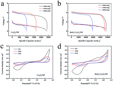
We decorated the Co3O4 nanowires with RuO2, which has been demonstrated to be effective for producing a cathode for ORR and OER to enhance the cycling properties of Li–O2 batteries. The electrochemical performance of the Co3O4/NiF and RuO2–Co3O4/NiF catalysts was then tested in assembled Li–O2 cells. Fig. 3a and b show the first discharge/charge curves for these Li–O2 batteries at different current densities of 100 mA g−1, 150 mA g−1 and 200 mA g−1 in a voltage window of 2.0–4.2 V. In these rate studies, the overpotential of both catalysts was almost the same, while there was a huge difference observed in their specific capacities. The discharge capacity of the Co3O4/NiF electrode was found to be 2406.6 mA h g−1 at 100 mA g−1, which was much lower than that of the RuO2–Co3O4/NiF electrode (9620 mA h g−1 under the same conditions), indicating the better ORR catalytic performance of RuO2–Co3O4 than that of Co3O4. The rate performances of the RuO2–Co3O4/NiF and Co3O4/NiF electrodes were further studied at higher discharge/charge current densities of 150 mA g−1 and 200 mA g−1. The discharge capacity of the RuO2–Co3O4/NiF based battery reached 9186.5 mA h g−1 and 5882.3 mA h g−1 at current densities of 150 mA g−1 and 200 mA g−1, respectively, while the Co3O4/NiF based battery only reached 1657.3 mA h g−1 and 1010.7 mA h g−1 under the same conditions. The high specific capacity indicated that the passivation of the electrode could be slowed due to the controllable 3D web structure and uniformly distributed RuO2.
Cyclic voltammograms (CVs) were recorded to study the ORR and OER properties of the RuO2–Co3O4/NiF and Co3O4/NiF electrodes. As shown in Fig. 3c and d, the CV curves of RuO2–Co3O4 and Co3O4 were measured in a voltage window of 2.0–4.3 V. Both the RuO2–Co3O4/NiF and Co3O4/NiF electrodes displayed a reduction peak during the cathodic scan and the ORR onset potentials of both electrodes were measured to be about 2.90 V, indicating the excellent catalytic performance for ORR. It is worth noting that the reduction peak current density of the RuO2–Co3O4 electrode was a bit higher than that of the Co3O4 electrode, which is related to the higher electrochemical activity and conductivity of the RuO2-doped catalyst. During the succeeding anodic scan process, a relatively strong oxidation peak could be observed at 3.60 V for RuO2–Co3O4 and the intensity of the following peaks was reduced. For the Co3O4/NiF electrode, the OER peak appeared until the second cycle. This phenomenon indicated that the RuO2–Co3O4/NiF electrode might have a better OER performance, and in general, the overall CV results demonstrated the much better catalytic activity of RuO2–Co3O4/NiF electrode.
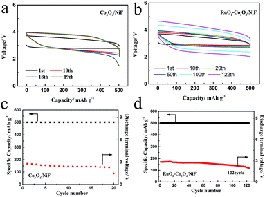
Fig. 4a shows the voltage profiles of the Co3O4-catalyzed Li–O2 battery with a fixed specific capacity of 500 mA h g−1 under a current density of 100 mA g−1 in the voltage range of 2.0–4.3 V. Although the discharge plateau of the battery was higher at 2.75 V and the charge plateau remained lower at 3.60 V in the first cycle, indicating an overpotential of 0.85 V, the cycling performance could only be maintained by up to 18 cycles, with a rapid voltage decrease below 2 V being observed at the 19th cycle, as shown in Fig. 4c. The cyclic performance of the battery could be greatly increased by using the RuO2–Co3O4/NiF catalyst. In Fig. 4b it can be seen that the RuO2–Co3O4/NiF based Li–O2 battery exhibits a lower overpotential of 0.7 V in the first cycle, which is much better than the performance of Co3O4/NiF. When the specific capacity is limited to 500 mA h g−1 at the same current density, the battery incorporating RuO2–Co3O4/NiF achieved a durable cycling performance of 122 cycles before the cut-off voltage at below 2 V (Fig. 4d). This result proves that the RuO2–Co3O4/NiF electrode could significantly increase the cycle life of a Li–O2 battery. A comparison of reported works and this work is shown in Table S1,† proving the superiority of the electrode synthesized in this work. We also studied the effects of Ru loading. Ru–Co3O4/NiF-catalyzed batteries were also used under these conditions, and the charge/discharge curves of the 40th cycles are shown in Fig. S3.† The Ru–Co3O4/NiF based Li–O2 battery exhibits an overpotential of 0.73 V in the 1st cycle, indicating the good catalytic performance brought about by the Ru loading. However, the overpotential increases to 1.24 V in the 40th cycle, which is much larger than that of RuO2–Co3O4/NiF (0.95 V, Fig. S4†). These results indicate that even though Ru–Co3O4/NiF has an electrocatalytic activity as high as that of RuO2–Co3O4/NiF, its cyclability is unsatisfactory. Therefore, RuO2 modified Co3O4/NiF was considered to be the best choice for improving the performance of the Li–O2 battery in this system.
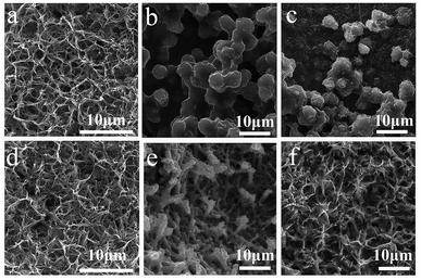
To investigate the growth mechanism of the discharge products of these two batteries equipped with different cathodes, ex-SEM characterization of the catalytic cathodes was implemented in both the discharged and charged states. Fig. 5 shows a schematic illustration of the formation of the discharge products on the surfaces of the Co3O4 nanowires and RuO2–Co3O4 nanowires, which exhibit different growth mechanisms of Li2O2 and briefly describe the following ex-SEM observations. Fig. 6 shows the SEM images of the Co3O4-catalyzed and RuO2–Co3O4-catalyzed cells in their initial states, and after discharging and charging, respectively. Fig. 6b shows an SEM image of the discharged Co3O4 electrode. It can be seen that Li2O2 grows on the surface of the Co3O4 nanowires, as well as between the nanowires. The knitted 3D web structure of the nanowires is fully covered by Li2O2. After charging, most of the intermediates remained undecomposed. Only a few decompose as the size of the ball-like intermediates decreased from ∼8 μm to ∼3 μm (Fig. 6c). For RuO2–Co3O4, its knitted 3D web structure was maintained after Li2O2 deposition (Fig. 6e), which was indicated by the Raman results shown in Fig. S5.† Four characteristic peaks from Co3O4 located at 189, 471, 514 and 678 cm−1 correspond to the 2F2g, 1Eg, and 1A1g Raman active modes of the Co3O4 nanocrystals, respectively.50 The other two peaks correspond to the stretching mode of O2-2 (vs. Li2O2) at 798 cm−1 and the lattice modes at 267 cm−1.51,52 An enlarged SEM image can be found in Fig. S6,† showing that the Ru-doped Co3O4 nanowires were evidently covered with Li2O2 sheets. According to Lee's work, during discharge, Li2O2 grows on the surface of the nanowires little by little until the whole surface of the nanowires is covered with Li2O2.53 Our results are similar to theirs. In contrast to the pristine Co3O4 nanowires, the knitted 3D web nanowires remained unbroken after charging (Fig. 6f), suggesting enhanced mechanical strength and a better performance.
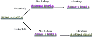 | ||
| Fig. 5 Schematic illustrations of the formation of discharge products on the surfaces of Co3O4 nanowires and RuO2–Co3O4 nanowires. | ||
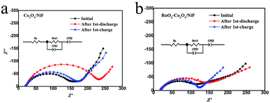
In order to further investigate the variation of the intermediates (Li2O2) formed in Li–O2 batteries at different discharge/charge stages, the electrochemical impedance spectra (EIS) of Li–O2 batteries with Co3O4/NiF and RuO2–Co3O4/NiF catalysts were measured. The Nyquist plots containing a semicircle and a sloping line were fitted by employing the equivalent circuit, as shown in the insets in Fig. 7, and the fitting results are summarized in Table 1. It is obvious that the impedance of both Li–O2 batteries increased for the poor electronic conductive discharge products (Li2O2) formed during discharging. After the charging process, the impedance of the Li–O2 batteries with the Co3O4/NiF cathode increased (Fig. 7a), indicating that the discharge products were not fully decomposed upon charging. On the contrary, the Li–O2 batteries with the RuO2–Co3O4/NiF cathode almost recovered the initial impedance after the charge process (Fig. 7b). This indicated that the generated discharge products were almost completely decomposed after charging, which is consistent with the SEM results. Hence, the EIS results confirmed the microstructure observation and electrochemical experiments and further confirmed the unique properties of the Li–O2 batteries with a RuO2–Co3O4/NiF catalyst.
| Co3O4-catalyzed Li–O2 batteries | Cdl | |||
|---|---|---|---|---|
| Ro (Ω) | Rct (Ω) | Y | n | |
| Initial | 18.60 | 131.6 | 2.16 × 10⁻⁵ | 0.79 |
| After discharge | 19.74 | 224.1 | 8.34 × 10⁻⁵ | 0.81 |
| After charge | 18.86 | 152.7 | 7.48 × 10⁻⁵ | 0.77 |
| RuO2-Co3O4-catalyzed Li–O2 batteries | Cdl | |||
|---|---|---|---|---|
| Ro (Ω) | Rct (Ω) | Y | n | |
| Initial | 17.14 | 102.8 | 3.38 × 10⁻⁵ | 0.71 |
| After discharge | 17.80 | 130.1 | 2.85 × 10⁻⁴ | 0.74 |
| After charge | 19.04 | 107.5 | 2.19 × 10⁻⁴ | 0.80 |
Conclusions
In summary, RuO2–Co3O4 with a 3D web microstructure was prepared via a simple hydrothermal method followed by impregnation and an annealing treatment. The 3D web freestanding Co3O4 nanowires growing on the surface of NiF offer a porous structure for O2 diffusion, and provide a large surface space for the loading of RuO2 nanoparticles, as well as Li2O2 formation and decomposition. The uniformly distributed RuO2 particles boost the catalytic activity of the Li–O2 batteries. Hence, the 3D porous structure of the freestanding Co3O4 nanowires loaded with RuO2 was maintained after Li2O2 deposition and the discharge products were fully decomposed after charging. Therefore, Li–O2 batteries with the freestanding RuO2–Co3O4/NiF cathode achieved a higher specific capacity and advanced cycling performance. When measurements were conducted at a limited specific capacity of 500 mA h g−1 at a current density of 100 mA g−1, the RuO2–Co3O4/NiF based Li–O2 battery achieved 122 stable cycles. In other words, this excellent catalytic cathode material is worthy of further investigation in the field of Li–O2 batteries.Conflicts of interest
The authors declare no conflict of interest.Acknowledgements
This work was supported financially by the National Basic Research Program of China (No. 2016YFB0100201); the National Natural Science Foundation of China (No. 21706279); the Science Foundation of the China University of Petroleum, Beijing (C201604, No. 2462014YJRC003) and the State Key Laboratory of Physical Chemistry of Solid Surfaces, Xiamen University (No. 201703).Notes and references
- K. M. Abraham, J. Phys. Chem. Lett., 2015, 6, 830–844 CrossRef PubMed.
- P. G. Bruce, S. A. Freunberger, L. J. Hardwick and J. M. Tarascon, Nat. Mater., 2012, 11, 19–29 CrossRef PubMed.
- H. D. Lim, K. Y. Park, H. Song, E. Y. Jang, H. Gwon, J. Kim, Y. H. Kim, M. D. Lima, R. R. Ovalle and X. Lepró, Adv. Mater., 2013, 25, 1348 CrossRef PubMed.
- A. C. Luntz and B. D. Mccloskey, Chem. Rev., 2014, 114, 11721–11750 CrossRef PubMed.
- B. D. Mccloskey, R. Scheffler, A. Speidel, D. S. Bethune, R. M. Shelby and A. C. Luntz, J. Am. Chem. Soc., 2011, 133, 18038 CrossRef PubMed.
- M. M. Ottakam Thotiyl, S. A. Freunberger, Z. Peng, Y. Chen, Z. Liu and P. G. Bruce, Nat. Mater., 2013, 12, 1050–1056 CrossRef PubMed.
- F. Li and J. Chen, Adv. Energy Mater., 2017, 7, 1602934 CrossRef.
- J. J. Xu, Z. W. Chang, Y. Wang, D. P. Liu, Y. Zhang and X. B. Zhang, Adv. Mater., 2016, 28, 9620–9628 CrossRef PubMed.
- J. Xiao, J. Hu, D. Wang, D. Hu, W. Xu, G. L. Graff, Z. Nie, J. Liu and J. G. Zhang, J. Power Sources, 2011, 196, 5674–5678 CrossRef.
- B. D. Mccloskey, A. Speidel, R. Scheffler, D. C. Miller, V. Viswanathan, J. S. Hummelshøj, J. K. Nørskov and A. C. Luntz, J. Phys. Chem. Lett., 2012, 3, 997 CrossRef PubMed.
- M. Balaish, A. Kraytsberg and Y. Ein-Eli, Phys. Chem. Chem. Phys., 2014, 16, 2801–2822 RSC.
- G. A. Elia, J.-B. Park, B. Scrosati, Y.-K. Sun and J. Hassoun, Electrochem. Commun., 2013, 34, 250–253 CrossRef.
- C. Li, O. Fontaine, S. A. Freunberger, L. Johnson, S. Grugeon, S. Laruelle, P. G. Bruce and M. Armand, J. Phys. Chem. C, 2014, 118, 3393–3401 CrossRef.
- Z. Liu, N. Feng, Z. Shen, F. Li, P. He, H. Zhang and H. Zhou, ChemSusChem, 2017, 10, 2714–2719 CrossRef PubMed.
- D. Zhai, H. H. Wang, J. Yang, K. C. Lau, K. Li, K. Amine and L. A. Curtiss, J. Am. Chem. Soc., 2013, 135, 15364–15372 CrossRef PubMed.
- N. Mahne, B. Schafzahl, C. Leypold, M. Leypold, S. Grumm, A. Leitgeb, G. A. Strohmeier, M. Wilkening, O. Fontaine, D. Kramer, C. Slugovc, S. M. Borisov and S. A. Freunberger, Nat. Energy, 2017, 2, 17036 CrossRef.
- C. Cao, Y. Yan, H. Zhang, J. Xie, S. Zhang, B. Pan, G. Cao and X. Zhao, ACS Appl. Mater. Interfaces, 2016, 8, 31653–31660 CrossRef PubMed.
- Y. Shao, F. Ding, J. Xiao, J. Zhang, W. Xu, S. Park, J.-G. Zhang, Y. Wang and J. Liu, Adv. Funct. Mater., 2013, 23, 987–1004 CrossRef.
- R. S. Assary, J. Lu, P. Du, X. Luo, X. Zhang, Y. Ren, L. A. Curtiss and K. Amine, ChemSusChem, 2013, 6, 51–55 CrossRef PubMed.
- X. Guo, B. Sun, D. Su, X. Liu, H. Liu, Y. Wang and G. Wang, Sci. Bull., 2017, 62, 442–452 CrossRef.
- Y. Ren, S. Zhang, H. Li, X. Wei and Y. Xing, Appl. Surf. Sci., 2017, 420, 222–232 CrossRef.
- Q. C. Zhu, F. H. Du, S. M. Xu, Z. K. Wang, K. X. Wang and J. S. Chen, ACS Appl. Mater. Interfaces, 2015, 8, 3868 CrossRef PubMed.
- C. Shu, Y. Liu, J. Long, X. Chen and Y. Su, Part. Part. Syst. Charact., 2018, 1700433 CrossRef.
- Q. C. Zhu, F. H. Du, S. M. Xu, Z. K. Wang, K. X. Wang and J. S. Chen, ACS Appl. Mater. Interfaces, 2015, 8, 3868 CrossRef PubMed.
- C. Guan, A. Sumboja, H. Wu, W. Ren, X. Liu, H. Zhang, Z. Liu, C. Cheng, S. J. Pennycook and J. Wang, Adv. Mater., 2017, 29(44), 1704117 CrossRef PubMed.
- S. M. Xu, Q. C. Zhu, F. H. Du, X. H. Li, X. Wei, K. X. Wang and J. S. Chen, Dalton Trans., 2015, 44, 8678 RSC.
- R. Gao, Z. Yang, L. Zheng, L. Gu, L. Liu, Y. Lee, Z. Hu and X. Liu, ACS Catal., 2018, 8, 1955–1963 CrossRef.
- X. Han, F. Cheng, C. Chen, F. Li and J. Chen, Inorg. Chem. Front., 2016, 3, 866–871 RSC.
- Y. M. Cui, Z. Y. Wen and Y. Liu, Energy Environ. Sci., 2011, 4, 4727–4734 RSC.
- S. A. Freunberger, Y. Chen, N. E. Drewett, L. J. Hardwick, F. Barde and P. G. Bruce, Angew. Chem., Int. Ed. Engl., 2011, 50, 8609–8613 CrossRef PubMed.
- H. Lee, Y. J. Kim, J. L. Dong, J. Song, M. L. Yong, H. T. Kim and J. K. Park, J. Mater. Chem. A, 2014, 2, 11891–11898 RSC.
- M. He, P. Zhang, S. Xu and X. B. Yan, ACS Appl. Mater. Interfaces, 2016, 8, 23713–23720 CrossRef PubMed.
- J. Y. Cao, S. Y. Liu, J. Xie, S. C. Zhang, G. S. Cao and X. B. Zhao, ACS Catal., 2015, 5, 241–245 CrossRef.
- L. Leng, X. Zeng, H. Song, T. Shu, H. Wang and S. Liao, J. Mater. Chem. A, 2015, 3, 15626–15632 RSC.
- H. Huang, S. Luo, C. Liu, Q. Wang, Z. Wang, Y. Zhang, A. Hao, Y. Liu, J. Li, Y. Zhai and Y. Dai, J. Alloys Compd., 2017, 726, 939–946 CrossRef.
- C. Xu, B. M Gallant, P. U Wunderlich, T. Lohmann and J. Greer, ACS Nano, 2015, 9(6), 5876–5883 CrossRef PubMed.
- H. G. Jung, Y. S. Jeong, J. B. Park, Y. K. Sun, B. Scrosati and Y. J. Lee, ACS Nano, 2013, 7, 3532 CrossRef PubMed.
- L. Huang, Y. Mao, G. Wang, X. Xia, J. Xie, S. Zhang, G. Du, G. Cao and X. Zhao, New J. Chem., 2016, 40, 6812–6818 RSC.
- J. Jiang, P. He, S. Tong, M. Zheng, Z. Lin, X. Zhang, Y. Shi and H. Zhou, NPG Asia Mater., 2016, 8, e239 CrossRef.
- F. Li, D.-M. Tang, T. Zhang, K. Liao, P. He, D. Golberg, A. Yamada and H. Zhou, Adv. Energy Mater., 2015, 5, 1500294 CrossRef.
- F. Li, D. M. Tang, Z. Jian, D. Liu, D. Golberg, A. Yamada and H. Zhou, Adv. Mater., 2014, 26, 4659–4664 CrossRef PubMed.
- F. Li, D. M. Tang, Y. Chen, D. Golberg, H. Kitaura, T. Zhang, A. Yamada and H. Zhou, Nano Lett., 2013, 13, 4702–4707 CrossRef PubMed.
- K. M. Liao, T. Zhang, Y. Q. Wang, F. J. Li, Z. L. Jian, H. J. Yu and H. S. Zhou, Chemsuschem, 2015, 8, 1429–1434 CrossRef PubMed.
- J. Liu, Y. Ma, M. Roberts, T. Gustafsson, K. Edström and J. Zhu, J. Power Sources, 2017, 352, 208–215 CrossRef.
- Y. G. Huang, J. Chen, X. H. Zhang, Y. H. Zan, X. M. Wu, Z. Q. He, H. Q. Wang and Q. Y. Li, Chem. Eng. J., 2016, 296, 28–34 CrossRef.
- G. Y. Zhao, Z. M. Xu and K. N. Sun, J. Mater. Chem. A, 2013, 1, 12862–12867 RSC.
- R. Gao, J. Zhu, X. Xiao, Z. Hu, J. Liu and X. Liu, J. Phys. Chem. C, 2015, 119, 4516–4523 CrossRef.
- M. Zhou, C.-Y. V. Li and K.-Y. Chan, Energy Technol., 2017, 5, 732–739 CrossRef.
- D. Su, S. Dou and G. Wang, Sci. Rep., 2014, 4, 5767 CrossRef PubMed.
- J. K. Zhang, P. F. Li, Z. H. Wang, J. S. Qiao, D. Rooney, W. Sun and K. N. Sun, J. Mater. Chem. A, 2015, 3, 1504–1510 RSC.
- M. Dunuwille, M. Kim and C. S. Yoo, J. Chem. Phys., 2016, 145, 084701 CrossRef PubMed.
- D. Zhai, H. H. Wang, J. Yang, K. C. Lau, K. Li, K. Amine and L. A. Curtiss, J. Am. Chem. Soc., 2013, 135, 15364–15372 CrossRef PubMed.
- H. Lee, Y.-J. Kim, D. J. Lee, J. Song, Y. M. Lee, H.-T. Kim and J.-K. Park, J. Mater. Chem. A, 2014, 2, 11891 RSC.
Footnotes |
| † Electronic supplementary information (ESI) available. See DOI: 10.1039/c8ra03325k |
| ‡ These authors contributed equally to this work. |
| This journal is © The Royal Society of Chemistry 2018 |

