
 Open Access Article
 This Open Access Article is licensed under a Creative Commons Attribution-Non Commercial 3.0 Unported Licence
A core–shell structured polyacrylonitrile@poly(vinylidene fluoride-hexafluoro propylene) microfiber complex membrane as a separator by co-axial electrospinning†
Shuting Yang abc,
Wenhao Maabc,
Aili Wangabc,
Jifeng Guabc and
Yanhong Yin*abc
abc,
Wenhao Maabc,
Aili Wangabc,
Jifeng Guabc and
Yanhong Yin*abc
aSchool of Chemistry and Chemical Engineering, Henan Normal University, Xinxiang, Henan 453007, P. R. China. E-mail: yyh3326439@foxmail.com
bNational & Local Joint Engineering Laboratory for Motive Power and Key Materials, Xinxiang, Henan 453007, China
cCollaborative Innovation Center of Henan Province for Motive Power and Key Materials, Xinxiang, Henan 453007, China
First published on 27th June 2018
Abstract
A novel and facile core–shell structured polyacrylonitrile@poly (vinylidene fluoride-hexafluoro propylene) (PAN@PVDF-HFP) microfiber complex membrane was designed and fabricated via co-axial electrospinning, which was used as a separator in lithium-ion batteries. Poly(vinylidene fluoride-co-hexafluoro propene) (PVDF-HFP) and polyacrylonitrile (PAN) were used as the shell (outer) layer and core (inner), respectively. Structure, surface morphology, porosity, and thermal properties of the core–shell structured microfiber membranes were investigated. Compared with the traditional commercial porous polyethylene (PE) separator, the PAN@PVDF-HFP microfiber complex membranes exhibited higher porosity, superior thermal stability, better electrolyte wettability and higher ionic conductivity. As a consequence, batteries assembled with the PAN@PVDF-HFP microfiber complex membrane display better cycling stability and superior rate performance compared to those with the PE separator.
1 Introduction
With the increasing demands for energy storage systems and equipment, rechargeable lithium-ion batteries (LIBs) have received considerable attention. They have been applied widely in a variety of electrical devices and equipment, even automotive vehicles, owing to their relatively higher power density/energy density, longer cycling life, and lower memory effect.1–5As one of the main components in LIBs, the separator is used to separate the anode and cathode to avoid electrical short circuits, and permit the transportation of ions between them during the charge/discharge procedure.4,6–9 At present, microporous polyolefin separators, such as polypropylene (PP) and polyethylene (PE) fabricated by the dry or wet processes, are widely used owing to their outstanding mechanical strength and stability.6,10–12 Whereas the polyolefin separators usually show huge dimensional shrinkage at an elevated temperature, which may result in a serious internal short circuit, leading to battery thermal runaway.13–15 In addition, the poor wettability caused by the distinct difference in polarity between polar organic solvents and hydrophobic polyolefin separator can result in high ionic resistance. So, selecting a suitable separator is essential for ensuring battery safety and achieving desired battery performance.16–18
To address these problems, many efforts have been devoted to improving the wettability and thermal stability of the separators.15–17,19–26 One of the most common ways is to coat inorganic nanoparticles (SiO2, Al2O3, etc.) on the surface of polyolefin membranes (PE, PP, etc.).23,27–29 Unfortunately, the solution coating method suffers from poorly bonded nanoparticles and decreased porosity. The other one strategy is to fabricate polymeric nonwovens from heat-resistant resins. Kinds of groups have demonstrated separators using different polymers, such as polyethylene terephthalate (PET),30 polyimide (PI),20 polyvinylidene fluoride (PVDF),19,31 and poly(vinylidene fluoride-co-hexa fluoropropylene) (PVDF-HFP)32,33 with high electrolyte uptake, porosity, ionic conductivity, rate performance and better cycling performances. Sun et al.34 have proved that through adopting complex materials to prepare separators, it is possible to improve the battery safety. In summary, it is effective to prepare complex separator utilizing the complementary advantages between different materials.
PVDF-HFP has been proved to be an excellent polymer electrolyte material with relatively high ionic conductivity. It is inert with common anode and cathode materials in electrolytes for lithium-ion batteries. Meanwhile, it is insoluble and stable within the reductive/oxidative electrochemical environment inside the battery. Nevertheless, its melting point is only 130 °C,35 which is relatively low for LIBs separator. PAN is a kind of polymer with excellent flame retardant property and high resistance to effect of heat.36,37 It also shows a wide electrochemical stability window. So recombination of PAN and PVdF-HFP may form an excellent LIBs separator. Anantha Gopala38 and Prasanth Raghavan39 prepared electrospun membrane by blending PAN and PVDF-HFP. However, PAN has a great swelling phenomenon in the electrolyte, this work is aimed to prepare a core–shell structured microfiber complex membrane via coaxial electrospinning technology with PVDF-HFP as shell material for its stability in electrolyte and PAN as core material for its thermally stable mechanical property.
Electrospinning has been regarded as an effective technique for the fabrication of polymer microfibers, which can form porous membrane with high porosity, specific surface area and absorption rate of liquid.30,35,36,40–43 In addition, it is easy to prepare complex polymer microfibers, such as a core–shell structured one, through coaxial electrospinning technology.
In this work, a PAN@PVDF-HFP core–shell structured microfiber complex membrane was fabricated via coaxial electrospinning technology. Here, the thermally stable PAN acts as a mechanical support which will contribute to decreasing the thermally induced dimensional shrinkage of the complex nonwoven separator. And PVDF-HFP was chosen as the protective shell because of its stability in electrolyte and the reductive/oxidative electrochemical environment in the battery. As a result, the core–shell structured PAN@PVDF-HFP microfiber membranes exhibit a higher absorption rate of liquid, higher heat resistance, higher ionic conductivity, excellent rate performance and cycle stability compared to the traditional PE separator.
2 Experimental
2.1 Chemical and equipment
PAN (Mw = 90![[thin space (1/6-em)]](https://www.rsc.org/images/entities/char_2009.gif) 000) was purchased from KunShan Hongyu Plastics Co., Ltd. PVdF-HFP (PVDF 75130) was supplied by Solvay S.A. Dimethyl Formamide (DMF) (99%) was from Tianjin Fu Chen Chemical Reagent Factory. N-Butanol was purchased from Sigma Aldrich. Commercialized polyethylene (PE) separator (25 μm) was from Green, China. And all the chemicals were used as received. Electrospinning Equipment (ET-2335H) was bought from Beijing Ucalery Technology Development Co., Ltd. Injection syringes was ordinary 10 ml plastic injection syringe for temporary use.
000) was purchased from KunShan Hongyu Plastics Co., Ltd. PVdF-HFP (PVDF 75130) was supplied by Solvay S.A. Dimethyl Formamide (DMF) (99%) was from Tianjin Fu Chen Chemical Reagent Factory. N-Butanol was purchased from Sigma Aldrich. Commercialized polyethylene (PE) separator (25 μm) was from Green, China. And all the chemicals were used as received. Electrospinning Equipment (ET-2335H) was bought from Beijing Ucalery Technology Development Co., Ltd. Injection syringes was ordinary 10 ml plastic injection syringe for temporary use.
2.2 Fabrication of the PAN@PVdF-HFP microfiber complex membranes
A schematic diagram of the fabrication course of the core–shell structured PAN@PVDF-HFP microfiber membranes was presented in Fig. 1, 1 g PAN or PVDF-HFP was dissolved in 10 ml DMF solvent (10 wt%), which was used as core or shell material, respectively. The solutions were enclosed in the syringes and exported at a flow rate of 0.04 mm min−1 for PAN and 0.06 mm min−1 for PVDF-HFP, respectively. Between the collector (aluminum drum) and the nozzle of the syringe, a potential difference of 20 kV was kept at 25 °C. The distance between the collector and the syringe tip was kept 20 cm. The thickness of our complex separator is 70 μm. As contrast, pure PAN and PVDF-HFP membranes were fabricated with a single needle at a flow rate of 0.10 mm min−1 with a potential difference of 20 kV.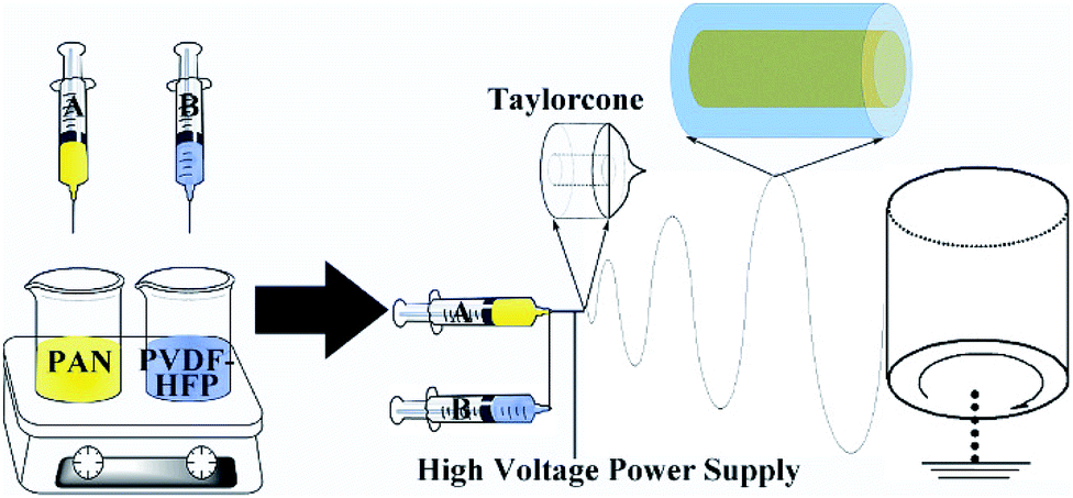 | ||
| Fig. 1 Schematic diagram of the fabrication course of the core–shell structured PAN@PVDF-HFP microfiber complex membranes. | ||
2.3 Physical properties characterization
The morphology of the separators were examined using a field emission scanning electron microscope (FESEM, JSM-6700F). The structure of the separators were observed by a Transmission electron microscope (TEM, JEM 2100) with an accelerating voltage of 200 kV. X-ray photoelectron spectroscopy (XPS) analysis was performed using a Kratos Axis Ultra spectrometer with a monochromatic Al Kα radiation (hν = 1486.6 eV).Porosities (P) of the separators were evaluated with n-butanol uptake tests, which was calculated based on the following eqn (1):
 | (1) |
Electrolyte uptake (EU) of the separator was measured with the following eqn (2):
 | (2) |
:1:1, v/v/v)) for a certain time.
Contact angles between separator and liquid electrolyte were measured using 6 μL electrolyte droplet with a Contact Angle Analyze (OCA40 Micro, Dataphysics company in Germany).
Thermal dimensional stability of the separators was measured after certain heat treatment process for 30 min. Thermal shrinkage (TS) rate was calculated from the area change before and after the heat process based on the following eqn (3):
 | (3) |
Mechanical property of the separators was carried out on an electronic universal testing machine (CMT4104, China) at a stretching rate of 1.0 mm s−1. Size of the tested samples is about 10 mm in width and 80 mm in length. The result is determined from the average value of three times measurements.
2.4 Electrochemical measurements
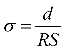
Ionic conductivity (σ) of the membrane was measured by Electrochemical Impedance Spectroscopy technique (CHI-760, CH Instruments) with the frequency range from 0.1 to100 kHz. And the AC perturbation is 5 mV. The electrolyte impregnated separator was placed between two stainless-steel (SS) plates (diameter: 1.60 cm). The conductivity was calculated based on the following eqn (4):
 | (4) |
The electrolyte soaked separator placed between a stainless steel (SS) and a lithium metal was assembled in a coin cell. Then linear sweep voltammetry (LSV) measurement was conducted with an electrochemical workstation (CHI-760, CH Instruments) with a scan rate of 1.0 mV s−1 from 3.0 V to 6 V.
Electrochemistry performances of the as-prepared films were tested in CR2032 type coin cells, with metal Li as the anode and LiFePO4 as the cathode. The cathode was composed of LiFePO4, polyvinylidene fluoride (PVDF) and conducting agent (Super-P) in a weight ratio of 8:1:1 with N-methyl-2-pyrrolidinone (NMP) as solvent. 1 M LiPF6 in ethylmethyl carbonate (EMC)/diethylene carbonate (DEC)/ethylene carbonate (EC) (1:1:1, v/v/v) was used as electrolyte. For comparison, commercialized PE separator (Green, China) was tested in the same condition. All the batteries were assembled in a glove box (Mbraun, Germany) filled with argon gas. Continuous current discharge–charge experiments were conducted in the voltage range of 2.5–4.2 V with a program-controlled battery test equipment (LAND CT2001A, China).
3 Results and discussion
Typical SEM images of the PAN@PVDF-HFP and commercial PE separator are presented in Fig. 2a and b. The complex nonwoven membrane (Fig. 2a) exhibits a 3D network structure with interconnected pores formed by smooth and uniform microfibers (about 400–500 nm), whose porosity is about 75%. While the commercial PE separator (Fig. 2b) of shows an elliptical hole structure with a porosity of only 35%. Membrane with relatively larger porosity can accommodate more electrolyte, which is benefit for the transportation of Li+. TEM image of the microfiber from the complex nonwoven membranes is given in Fig. 2c and d. The core–shell structure with the clear contrast between the dark center and the gray edge of the microfiber is found. Diameter of the microfiber in TEM was about 400–500 nm, which is in accordance with that in FESEM. Elemental information of the complex membranes surface is shown in the XPS survey spectrum (Fig. 2d), which confirms the existence of element C (287.8 eV, 290.8 eV) and F (688.15 eV). And there is not any N peaks, inferring that the majority of the microfibers show the formation of PAN core-PVDF-HFP shell structure. In this structure, the thermally stable PAN will act as a mechanical support to improve the thermal dimensional stability of the complex separator. And PVDF-HFP with good compatibility as shell material will contribute to the stability of the membrane.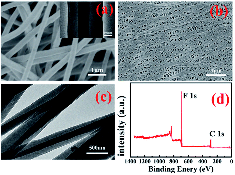 | ||
| Fig. 2 Morphologies of PAN@PVDF-HFP microfiber complex membranes (a) and commercial PE separator (b), TEM of PAN@PVDF-HFP (c) and (d), XPS survey spectra of PAN@PVDF-HFP membrane surface. | ||
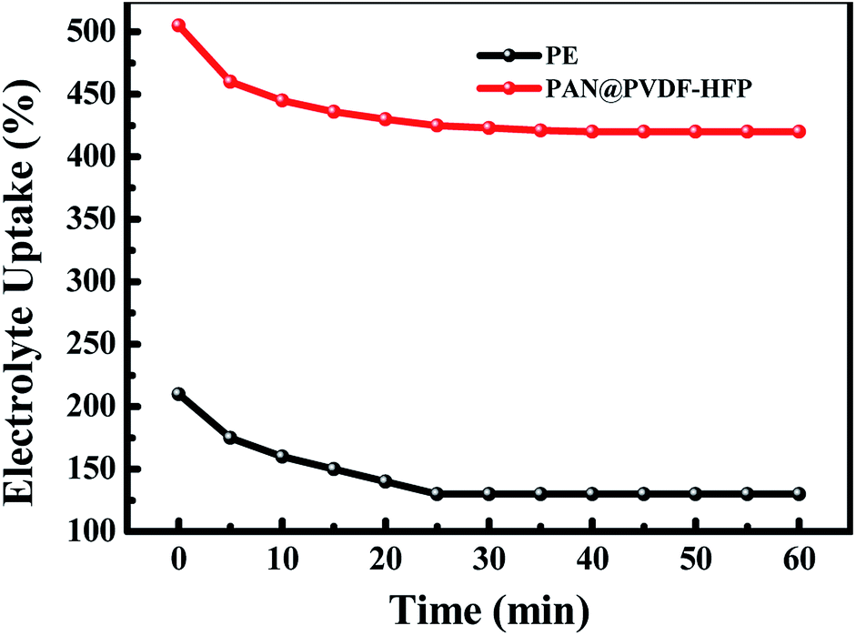
An ideal separator of lithium ion battery should be wet easily with the liquid electrolyte and hold the sufficient electrolyte for a long time, which made more emphasize on the lyophilic of the membrane. Contact angle images with liquid electrolyte droplet on the PAN@PVDF-HFP complex nonwoven and PE separator are shown in Fig. 3. The contact angle of PAN@PVDF-HFP complex nonwoven was 43°, lower than that of PE separator (97°). The lower contact angle implied that the PAN@PVDF-HFP complex nonwoven is more lyophilic to liquid electrolyte, which was beneficial to increasing the liquid absorbability of membrane. Fig. 4 compared the diffusion rate and the electrolyte immersion height of different separators. After being dropped onto the surface of the after 60 s. Analogously, the PAN@PVDF-HFP complex membrane exhibited higher electrolyte immersion-height (28 mm) than the PE (10 mm), which was ascribed to the hydrophobicity of polyethylene, which caused low affinity with the electrolyte. Fig. 5 displayed the electrolyte uptake of the PAN@PVDF-HFP and PE membranes as a function of time at room temperature. The initial electrolyte uptake of PAN@PVDF-HFP was 505%. And it stabilized to 420% after 60 min in the ambient atmosphere at room temperature, which falls in between that of pure PAN and PVDF-HFP (Table S1†). While that of PE changes from 210% to 130%, suggesting the excellent liquid absorbability of PAN@PVDF-HFP membrane. The superior liquid electrolyte wettability and high retention rate of the complex membrane may result from the unique structure of the nonwoven and the excellent affinity between electrolyte and PVDF-HFP, which will contributed to improving the cycle and rate capability performance of lithium ion batteries.
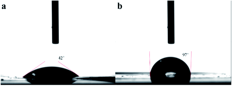 | ||
| Fig. 3 Contact angle images with liquid electrolyte droplet on the PAN@PVDF-HFP complex nonwoven (a), and PE separator (b). | ||
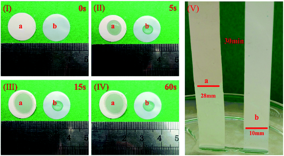 | ||
| Fig. 4 Photographs of the PAN@PVDF-HFP and PE membranes taken immediately after dropping of electrolyte (I, II, III, IV); contrast of liquid electrolyte immersion-height between PAN@PVDF-HFP and PE membranes (V). | ||
 | ||
| Fig. 5 The electrolyte uptake of the PE and PAN@PVdF-HFP membrane as a function of time at room temperature. | ||
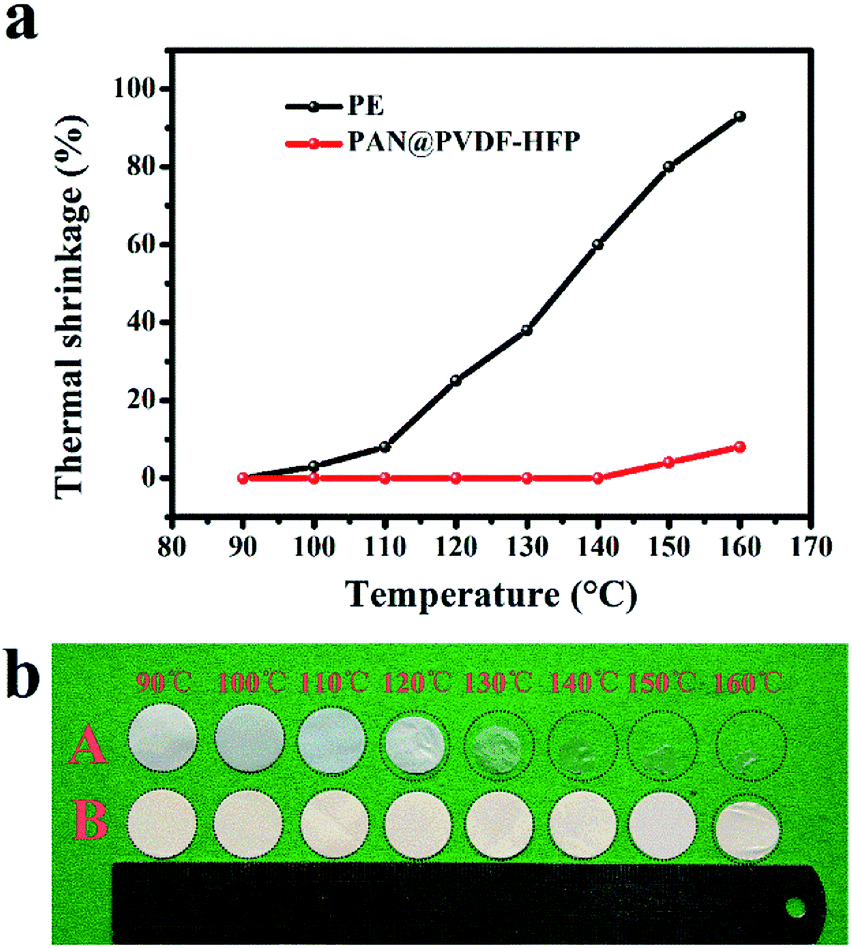
Thermal shrinkage was a crucial element to evaluate the thermal stability of separators. As seen in Fig. 6 a and b, after heating at different temperature for 30 min, PE separators showed obvious shrinkage at 120 °C. And it transformed from white to transparent at 130 °C, which meant holes in it have shut off at this temperature. While PAN@PVDF-HFP separators showed no obvious changes until 150 °C. The comparative picture of PE, PVDF-HFP, PAN@PVDF-HFP and PAN is provided in ESI Fig. S1.† The thermal shrinkage of pure PAN is better than that of PVDF-HFP and PE. After the combination of PAN and PVDF-HFP, the thermal shrinkage performance is obviously improved. It revealed that the PAN@PVDF-HFP separator showed better heat resistance than PE separator, which can improve security performance of lithium ion batteries.
 | ||
| Fig. 6 (a) Relationship of thermal shrinkage with temperature, (b) photograph of the PE and PAN@PVDF-HFP membrane after heating at different temperatures for 30 min. | ||
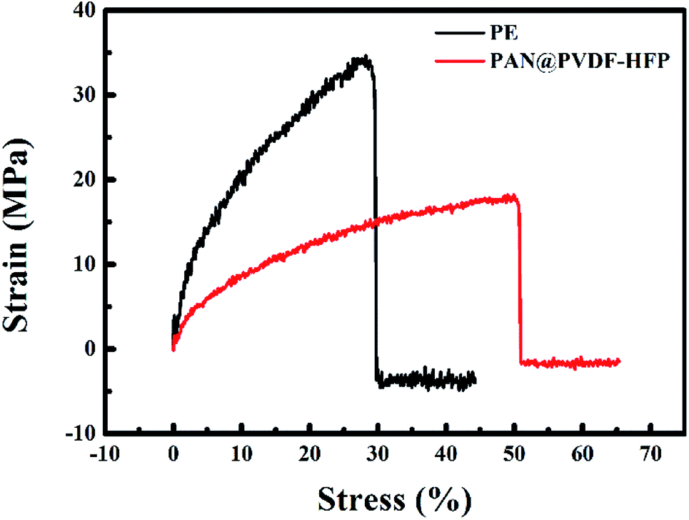
In consideration of the security issue, high mechanical strength is a vital factor for ideal separators. Stress–strain curves of the PE and PAN@PVdF-HFP membranes are depicted in Fig. 7. The commercial PE separator exhibits a tensile strength of 34.6 MPa and a deformation of 29%. However, the maximum tensile strength of PAN@PVdF-HFP complex membrane is 18.9 MPa and its deformation is up to 51%, implying that the stress performance of the complex membrane is slightly weaker than that of the PE separator but its strain performance is excellent. Such mechanical performances could meet the technical requirements for most conventional winding machines used in battery fabrication.
 | ||
| Fig. 7 Stress–strain curves of PE membranes and PAN@PVdF-HFP complex membranes. | ||
Ionic conductivity of the separators was determined by the Electrochemical Impedance Spectroscopy. Fig. 8a showed the Nyquist plots for the electrolyte-soaked porous PE and PAN@PVDF-HFP complex membranes. No semicircles were observed in the high frequency region, implying that the total conductivity results from the ionic conductivity. Nyquist plots exhibit almost vertical lines, suggesting near pure resistive behavior at high frequency. The bulk resistance of PAN@PVDF-HFP is 2.0 Ω, while that of PE is 5.0 Ω. The σ values calculated based on eqn (3) are 1.74 mS cm−1 and 0.52 mS cm−1, respectively. The σ values of PVDF-HFP and PAN are 1.73 mS cm−1 and 1.29 mS cm−1 which is provided in ESI Fig. S2.† Obviously, higher ionic conductivity is beneficial to decrease the polarization and enhance the rate performance of cells. The electrochemical stability windows of different separators were observed from the linear sweep voltammograms experiment. Fig. 8b shows that the electrolyte decomposes at about 4.4 V (vs. Li+/Li) with PE separator. While there is no obvious decomposition below 5.0 V (vs. Li+/Li) with PAN@PVDF-HFP complex separator. This superior stability may be attributed to the superior interfacial compatibility and better electrolyte retention of the complex nonwoven.
 | ||
| Fig. 8 (a) Nyquist plots of the batteries (SS/separator/SS) for the liquid electrolyte-soaked porous PE and PAN@PVDF-HFP complex membranes. (b)Linear sweep voltammograms of PE and PVDF-HFP at a scan rate of 1.0 mV s−1 between 3.0–6.0 V. | ||
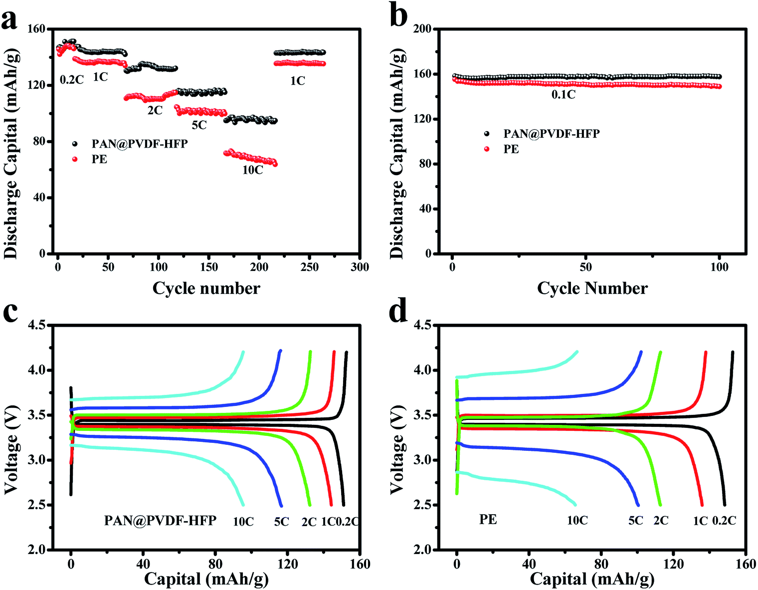
Fig. 9a depicted the rate performance of batteries with PE and as-prepared PAN@PVDF-HFP separators, respectively. When the current density increased from 0.2 to 10C, the discharging capacities of the cell with PE separator declined from 148 to 68 mA h g−1 rapidly, with a capacity retention of 46%. But relatively, that with the PAN@PVDF-HFP separator exhibited remarkable rate performance. Its capacity declined from 151 to 98 mA h g−1 with a relatively higher capacity retention of 65%. What's more, when the current density comes back to 1C, the capacity of PAN@PVDF-HFP recovered to 145 mA h g−1, which is still higher than that of PE (136 mA h g−1). The excellent rate performance can result from the relatively higher electrolyte uptake and electrical conductivity, which come from the feature of polymer electrolyte PVDF-HFP and the higher porosity of the membrane.
 | ||
| Fig. 9 C-rate performance (a) and cycle performance (b) of Li/LiFePO4 batteries with PAN@PVDF-HFP and PE membrane. Charge and discharge profiles of the batteries assembled with PAN@PVDF-HFP (c) and PE (d) separator at different current densities. | ||
For cycling stability test, the batteries with the complex separator and the commercial PE separator were measured at a current density of 0.1C for 100 cycles with a voltage range of 2.5–4.2 V. From Fig. 9b one can find that discharging capacities of the cell with PE membrane drops gradually from 154.9 mA h g−1 to 149 mA h g−1, with a capacity retention of 96.2% after 100 cycles. In contrast, the battery with PAN@PVDF-HFP separator showed relatively higher initial capacity (159.4 mA h g−1), and the capacity retention reaches 99.4% after 100 cycles. The rate and cycling discharging capacity comparisons of PE, PAN, PVDF-HFP, and PAN@PVDF-HFP are provided in ESI Fig. S3 and S4,† respectively. The discharging capacity of PAN and PVDF-HFP is lower than that of PAN@PVDF-HFP, but higher than that of PE. The improved capacity and stability of LIBs with the PAN@PVDF-HFP separators may be attributed to its relatively higher electrical conductivity and electrolyte uptake.
Fig. 9c and d shown the charge and discharge profiles of the cells assembled with PAN@PVDF-HFP complex nonwoven and PE separator. Capacities of the former at 0.2C, 1C, 2C, 5C and 10C were 151.3 mA h g−1, 144.1 mA h g−1, 134.8 mA h g−1, 116.7 mA h g−1 and 96.3 mA h g−1, respectively. While that of the latter were 147.4 mA h g−1, 136.2 mA h g−1, 110.5 mA h g−1, 101.4 mA h g−1 and 67.2 mA h g−1, respectively. In addition, with the increase of current density, the charge and discharge voltage platform of cell with PE separator shown larger polarization than that with PAN@PVDF-HFP complex membrane, inferring the better ion transportation performance of the latter.
To investigate whether or not the PAN@PVDF-HFP membrane has the ability to block particulates and dendrite growth, cells with PE and PAN@PVDF-HFP membranes were disassembled in a glove box. EDS analysis was taken on the membrane surface facing the metal lithium after 100 test cycles at 1C rate. The result is shown in Fig. 10. Element C, O, F and P can be found on the surface of separator facing the metal lithium. These four kinds of elements derive from separator, liquid electrolyte and LiPF6, respectively. Because PAN@PVDF-HFP is rich in F element, the mass percent of F element on PAN@PVDF-HFP is more than that on PE. Element Fe can't be found, which means that there are no traces of the cathode material both for the PE and PAN@PVDF-HFP membranes, implying that they can block the cathode particulates effectively. This may result from that although the pore size in the complex membrane seems relatively bigger than that in PE membrane, the pores in the complex membrane are superimposed. When the membrane is thick enough, it can also block particulates effectively. In addition, lithium slices after cycling were examined using a field emission scanning electron microscope. And the results are displayed in Fig. 11. Lithium dendrites are found on the surface of lithium anode with PE after 100 cycles. While surface of that with complex membrane is grainy which is covered by a relatively uniform SEI membrane, implying that the complex membrane has the ability to suppress the dendrite growth to some extent. This may be attributed to the relatively higher porosity and the excellent liquid absorbability of PAN@PVDF-HFP membrane, which is benefit for the uniform distribution of lithium ions.
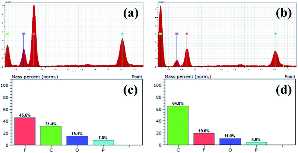 | ||
| Fig. 10 EDS of different separator facing Li metal anode after 100 cycles test at 1C rate, (a) PAN@PVDF-HFP, (b) PE, element content of different separator, (c) PAN@PVDF-HFP, (d) PE. | ||
 | ||
| Fig. 11 FE-SEM of lithium anode with PE (a) and PAN@PVDF-HFP (b) after 100 cycles test at 1C rate. | ||
4 Conclusion
Compared with the PE separator, the PAN@PVDF-HFP complex membranes exhibited higher porosity, superior thermal stability, higher ionic conductivity and better electrolyte wettability. The improved properties can be attributed to combining the merits of both PAN and PVDF-HFP, in which the former contributes to the improved thermal stability, while the latter to the better electrolyte wettability and higher ionic conductivity. It was also demonstrated that batteries assembled with the PAN@PVDF-HFP complex separator displayed better cycling stability and rate performance than those with PE separator, which suggesting that the PAN@PVDF-HFP complex membranes are very attractive for high performance LIBs.Conflicts of interest
There are no conflicts to declare.Acknowledgements
The authors acknowledge the National & Local Joint Engineering Laboratory for Motive Power and Key Materials for help and support.Notes and references
- S. S. Zhang, J. Power Sources, 2007, 164, 351–364 CrossRef.
- M. Armand and J. M. Tarascon, Nature, 2008, 451, 652–657 CrossRef PubMed.
- B. Dunn, H. Kamath and J. M. Tarascon, Science, 2011, 334, 928–935 CrossRef PubMed.
- J. B. Goodenough and K.-S. Park, J. Am. Chem. Soc., 2013, 135, 1167–1176 CrossRef PubMed.
- D. Larcher and J. M. Tarascon, Nat. Chem., 2015, 7, 19–29 CrossRef PubMed.
- P. Arora and Z. Zhang, Chem. Rev., 2004, 104, 4419–4462 CrossRef PubMed.
- X. Huang, J. Solid State Electrochem., 2011, 15, 649–662 CrossRef.
- H. Lee, M. Yanilmaz, O. Toprakci, K. Fu and X. Zhang, Energy Environ. Sci., 2014, 7, 3857–3886 RSC.
- X. Huang and J. Hitt, J. Membr. Sci., 2013, 425–426, 163–168 CrossRef.
- G. Venugopal, J. Moore, J. Howard and S. Pendalwar, J. Power Sources, 1999, 77, 34–41 CrossRef.
- W. Xiao, K. Zhang, J. Liu and C. Yan, J. Mater. Sci.: Mater. Electron., 2017, 28, 17516–17525 CrossRef.
- H. Liao, H. Zhang, H. Hong, Z. Li and Y. Lin, Electrochim. Acta, 2017, 257, 210–216 CrossRef.
- J. M. Tarascon and M. Armand, Nature, 2001, 414, 359–367 CrossRef PubMed.
- J. Kumar, P. Kichambare, A. K. Rai, R. Bhattacharya, S. Rodrigues and G. Subramanyam, J. Power Sources, 2016, 301, 194–198 CrossRef.
- J. Zhang, Z. Liu, Q. Kong, C. Zhang, S. Pang, L. Yue, X. Wang, J. Yao and G. Cui, ACS Appl. Mater. Interfaces, 2013, 5, 128–134 CrossRef PubMed.
- S. C. Chen, C. C. Wan and Y. Y. Wang, J. Power Sources, 2005, 140, 111–124 CrossRef.
- S. H. Yoo and C. K. Kim, Ind. Eng. Chem. Res., 2009, 48, 9936–9941 CrossRef.
- E. C. Evarts, Nature, 2015, 526, S93–S95 CrossRef PubMed.
- C. M. Costa, M. M. Silva and S. Lanceros-Méndez, RSC Adv., 2013, 3, 11404 RSC.
- C. Shi, P. Zhang, S. Huang, X. He, P. Yang, D. Wu, D. Sun and J. Zhao, J. Power Sources, 2015, 298, 158–165 CrossRef.
- G. Ma, F. Huang, Z. Wen, Q. Wang, X. Hong, J. Jin and X. Wu, J. Mater. Chem. A, 2016, 4, 16968–16974 RSC.
- C. Arbizzani, G. Gabrielli and M. Mastragostino, J. Power Sources, 2011, 196, 4801–4805 CrossRef.
- M. Kim and J. H. Park, J. Power Sources, 2012, 212, 22–27 CrossRef.
- Q. Wang, Z. Wen, J. Yang, J. Jin, X. Huang, X. Wu and J. Han, J. Power Sources, 2016, 306, 347–353 CrossRef.
- R. Song, R. Fang, L. Wen, Y. Shi, S. Wang and F. Li, J. Power Sources, 2016, 301, 179–186 CrossRef.
- L. Shi, F. Zeng, X. Cheng, K. H. Lam, W. Wang, A. Wang, Z. Jin, F. Wu and Y. Yang, Chem. Eng. J., 2018, 334, 305–312 CrossRef.
- Z. Zhang, Y. Lai, Z. Zhang, K. Zhang and J. Li, Electrochim. Acta, 2014, 129, 55–61 CrossRef.
- X. Zhao, Z. Zhang, S. Yang and G. Liang, Ceram. Int., 2017, 43, 14775–14783 CrossRef.
- C. Shi, J. Dai, C. Li, X. Shen, L. Peng, P. Zhang, D. Wu, D. Sun and J. Zhao, Polymers, 2017, 9, 159 CrossRef.
- M. Xia, Q. Liu, Z. Zhou, Y. Tao, M. Li, K. Liu, Z. Wu and D. Wang, J. Power Sources, 2014, 266, 29–35 CrossRef.
- Q.-Y. Wu, H.-Q. Liang, L. Gu, Y. Yu, Y.-Q. Huang and Z.-K. Xu, Polymer, 2016, 107, 54–60 CrossRef.
- J.-H. Kim, J.-H. Kim, E.-S. Choi, J. H. Kim and S.-Y. Lee, RSC Adv., 2014, 4, 54312–54321 RSC.
- Y.-Y. Lee and Y.-L. Liu, Electrochim. Acta, 2017, 258, 1329–1335 CrossRef.
- P. Sun, Y. Liao, X. Luo, Z. Li, T. Chen, L. Xing and W. Li, RSC Adv., 2015, 5, 64368–64377 RSC.
- X. Jiang, L. Xiao, X. Ai, H. Yang and Y. Cao, J. Mater. Chem. A, 2017, 5, 23238–23242 RSC.
- P. Carol, P. Ramakrishnan, B. John and G. Cheruvally, J. Power Sources, 2011, 196, 10156–10162 CrossRef.
- G. A. Elia, J. B. Ducros, D. Sotta, V. Delhorbe, A. Brun, K. Marquardt and R. Hahn, ACS Appl. Mater. Interfaces, 2017, 9, 38381–38389 CrossRef PubMed.
- A. Gopalan, P. Santhosh, K. Manesh, J. Nho, S. Kim, C. Hwang and K. Lee, J. Membr. Sci., 2008, 325, 683–690 CrossRef.
- P. Raghavan, X. Zhao, C. Shin, D.-H. Baek, J.-W. Choi, J. Manuel, M.-Y. Heo, J.-H. Ahn and C. Nah, J. Power Sources, 2010, 195, 6088–6094 CrossRef.
- J. W. Jung, C. L. Lee, S. Yu and I. D. Kim, J. Mater. Chem. A, 2016, 4, 703–750 RSC.
- F. Jiang, L. Yin, Q. Yu, C. Zhong and J. Zhang, J. Power Sources, 2015, 279, 21–27 CrossRef.
- Z. Liu, W. Jiang, Q. Kong, C. Zhang, P. Han, X. Wang, J. Yao and G. Cui, Macromol. Mater. Eng., 2013, 298, 806–813 CrossRef.
- Y. Liu, H. Ma, B. S. Hsiao, B. Chu and A. H. Tsou, Polymer, 2016, 107, 163–169 CrossRef.
Footnote |
| † Electronic supplementary information (ESI) available. See DOI: 10.1039/c8ra02035c |
| This journal is © The Royal Society of Chemistry 2018 |