 Open Access Article
Superior photocatalytic performance of LaFeO3/g-C3N4 heterojunction nanocomposites under visible light irradiation
Ke Xuab and
Jian Feng *b
*b
aDepartment of Biochemistry, Guizhou Education University, 115 Gaoxin Road, Guiyang, Guizhou 550018, China
bDepartment of Chemistry, School of Basic Medical Science, Guizhou Medical University, 9 Beijing Road, Guiyang, Guizhou 550004, China. E-mail: jfeng@gmc.edu.cn
First published on 22nd September 2017
Abstract
New types of LaFeO3/g-C3N4 heterostructures were successfully prepared and the enhanced photocatalytic hydrogen evolution and degradation activities under visible light irradiation were determined. They possessed the features of a Z-scheme photocatalysis system. The photoexcited electrons on the conduction band of LaFeO3 were transferred to the valence band of g-C3N4 by the solid–solid intimately contacted interfaces, where the electrons and holes were recombined, and thus improved the separation of photogenerated electrons and holes of g-C3N4. The LaFeO3/g-C3N4 heterostructures showed a higher hydrogen evolution rate and a higher amount of ˙OH than pure LaFeO3 and g-C3N4. The construction of the LaFeO3/g-C3N4 heterostructures was used to demonstrate an effective strategy for improving the photocatalytic property. The 5%-LaFeO3/g-C3N4 exhibited the highest photodegradation and water splitting rate. More than 95% of methylene blue (MB) was degraded after 15 min in the presence of 25 mg EDTA-2Na in 100 mL MB solution which was irradiated using a 3 W light-emitting diode. The 5%-LaFeO3/g-C3N4 heterojunction nanocomposite had a maximum hydrogen evolution rate of 158 μmol g−1 h−1.
1. Introduction
The rapid development of modern industry using the consumption of non-renewable fossil fuels has caused a serious global energy shortage and environmental pollution.1 As the largest renewable energy source, the exploitation of solar energy could mean less use of fossil fuels and thereby protect the environment. The utilization of solar energy using semiconductor-based photocatalysis has the capability of hydrogen (H2) evolution and pollutant removal, and is considered as an economical, renewable, clean and safe technology. A variety of semiconductor photocatalysts have been developed over the past few decades.2–5 Because visible light energy accounts for more than 40% of the sunlight energy, people are committed to developing visible light driven photocatalysts. So far, various visible light responsive semiconductor photocatalysts have been developed,6–9 but the fast charge recombination and insufficient stability still make it impractical for general use.Very recently, graphitic carbon nitride (g-C3N4) was found to be a promising metal-free material with a large surface area, high thermal and chemical stability, fast charge transfer rate, and a suitable bandgap of approximately 2.7 eV.10–13 It is consequently regarded as the next generation photocatalyst for water splitting and degradation of pollutants under visible light irradiation. However, the low photocatalytic efficiency of g-C3N4 caused by its narrow response range to visible light, fast recombination of photogenerated electron–hole pairs and low quantum efficiency limits its further applications. Therefore, researchers have focussed on different modification methods to improve its photocatalytic activity, including copolymerization,14 morphology control15 and doping.16 The construction of the g-C3N4–semiconductor heterostructures is an effective strategy to promote the separation of a photogenerated electron and hole, and thus improve the photocatalytic property.
A variety of nanocomposites have been reported in the literature for dye degradation and H2 evolution. Halogenides,17,18 sulfides19,20 and oxides21,22 have been developed to construct the heterojunction with g-C3N4. These g-C3N4–semiconductor heterostructures possess excellent photocatalytic performance in degradation of organic pollutants. Fu et al.17 reported novel heterojunctions of bismuth oxybromide–carbon nitride (BiOBr–C3N4) fabricated by depositing BiOBr nanoflakes onto the surface of C3N4. The optimum photocatalytic activity of the 0.5BiOBr–0.5C3N4 heterojunction was 4.9 and 17.2 times as high as those of individual BiOBr and C3N4, respectively, under visible light irradiation. Jiang et al.20 synthesized calcium indium sulfide (CaIn2S4)/g-C3N4 heterojunction nanocomposites using a two-step method. It exhibited a H2 evolution rate of 102 μmol g−1 h−1, which was more than 3 times that of pristine CaIn2S4. The highest activity was obtained for a 30% CaIn2S4/g-C3N4 heterojunction nanocomposite, over which 90% of methyl orange was degraded after 120 min. Zhao et al.21 prepared novel g-C3N4/tz-Bi0.92Gd0.08VO4 heterojunctions using a microwave hydrothermal method. The degradation rate of Rhodamine B was 94% after 20 min, which was 39.97% higher than that of g-C3N4. All the g-C3N4/tz-Bi0.92Gd0.08VO4 heterojunctions exhibited a higher degradation rate than that of the pure one. These g-C3N4–semiconductor heterostructures possess excellent photocatalytic performance in degradation of organic pollutants. However, there are only a few reports in the literature involving g-C3N4-based heterostructures with simultaneously enhanced photocatalytic degradation and H2 evolution performance.
Perovskite lanthanum ferric oxide (LaFeO3) has been applied to catalysts, sensors, environmental monitoring and membranes in syngas production.23,24 LaFeO3 exhibits an interesting catalytic activity in the degradation of chlorinated volatile organic compounds.25 LaFeO3 has a band gap of about 2.0 eV, which is advantageous for absorbing visible light, for good thermal stability and for high catalytic activity.26 In this work, LaFeO3/g-C3N4 Z-scheme photocatalysis system was constructed. The photoexcited electrons on the conduction band (CB) of LaFeO3 were transferred to the valence band (VB) of g-C3N4 by the solid–solid intimately contacted interfaces, where the electrons and holes were recombined, and thus improved the separation of the photogenerated electron and hole of g-C3N4. Combining this with a sacrificial agent [triethanolamine (TEOA) or ethylenediaminetetraacetic acid disodium salt (EDTA-2Na)] which reacted with the holes on the VB of LaFeO3, the photocatalytic efficiency was improved significantly. The LaFeO3/g-C3N4 Z-scheme photocatalysis system showed a higher H2 evolution rate and a higher amount of ˙OH than pure LaFeO3 and g-C3N4. More than 95% of methylene blue (MB) was degraded after 15 min in the presence of 25 mg EDTA-2Na in 100 mL MB solution irradiated using a 3 W light-emitting diode (LED). The 5%-LaFeO3/g-C3N4 heterojunction nanocomposite had a maximum H2 evolution rate of 158 μmol g−1 h−1.
2. Experimental
2.1 Chemicals
Iron(III) nitrate nonahydrate (Fe(NO3)3), lanthanum(III) nitrate hexahydrate (La(NO3)3) hexachloroplatinic acid (H2PtCl6), terephthalic acid, MB and melamine were purchased from Shanghai Aladdin Biochemical Technology Co., Ltd. All the chemicals were used without further purification.2.2 Preparation of LaFeO3/g-C3N4
Graphitic carbon nitride was prepared by the polycondensation of melamine (6 g) at 500 °C for 4 h in a muffle furnace. The ramping rate was 2 °C min−1. For a typical synthetic reaction of the LaFeO3/g-C3N4 nanocomposites, 2 g of g-C3N4, 0.1700 g of Fe(NO3)3, and 0.1800 g of La(NO3)3 were dissolved in 50 mL of deionized water (H2O) with stirring for 1 h. Then, the solution was evaporated to generate a solid product which was then ground into powder. The powder was placed in a crucible with a cover and then heated for another 2 h at 450 °C in a muffle furnace. The LaFeO3/g-C3N4 nanocomposites were obtained after cooling down the powder to room temperature. The as-prepared product was 5%-LaFeO3/g-C3N4. Changing the amounts of Fe(NO3)3, and La(NO3)3 added, 10%, 20%, 40% and 60% nanocomposites were synthesized. The as-prepared LaFeO3/g-C3N4 containing 5, 10, 20, 40, 60 wt% of LaFeO3 were denoted as LF1-5 or 5%-LaFeO3/g-C3N4 and so on.2.3 Characterization
Transmission electron microscopy (TEM) and high-resolution-TEM (HRTEM) images were performed on a FEI Tecnai G2 F20 transmission electron microscope. X-ray diffraction patterns (XRD) patterns were carried out on a Rigaku D/Max 2500 X-ray diffractometer with Cu Kα radiation (λ = 1.5406 Å). X-ray photoelectron spectroscopy (XPS) was carried out using an ESCA PHI500 spectrometer. Infrared spectra were obtained using a Nicolet NEXUS 470 Fourier-transform infrared spectroscopy (FTIR) instrument in the range of 4000–500 cm−1. Ultraviolet-visible (UV-vis) spectra were recorded on a Varian Cary 50 spectrophotometer. UV-vis diffuse reflectance spectra (DRS) were measured on Shimadzu UV-2401 spectrophotometer equipped with a spherical diffuse reflectance accessory.2.4 Photoelectrochemical measurement
A portion of photocatalyst (8 mg; g-C3N4, LaFeO3 or LaFeO3/g-C3N4), 2 mL of ethanol and 40 μL of 5 wt% Nafion were mixed to form a slurry. Then the suspension was dropped onto fluorine doped tin oxide (FTO) glass with an area of 1 cm2 which performed as the working electrode in a three-electrode system. Platinum (Pt) foil was selected as auxiliary electrode, and silver/silver chloride (Ag/AgCl) as reference electrode. A 3 W LED lamp was the light source. The photocurrent was measured in 0.2 M aqueous solution of sodium sulfate.2.5 Photocatalytic degradation of MB
The photocatalytic activities of photocatalysts (g-C3N4, LaFeO3 or LaFeO3/g-C3N4) were determined in a 5 mg L−1 aqueous solution of MB. For a typical photodegradation process, 100 mg of photocatalyst was dispersed in 100 mL of MB solution with magnetic stirring in dark for 30 min to reach an adsorption–desorption equilibrium. Then the photodegradation was tested under 3 W LED irradiation. A portion (5 mL) of reaction mixture was collected at the certain time intervals and centrifuged to remove the photocatalyst. The absorption peak at 664 nm was chose to determine the concentration of MB using a Varian Cary 50 spectrophotometer.2.6 Measurement of hydroxyl radicals
A 0.5 mM solution of terephthalic acid (TA) was obtained by dissolving TA in 2.0 mM sodium hydroxide. Then 100 mg photocatalyst was suspended in 100 mL of TA solution. The mixture was then irradiated under 3 W LED irradiation. A portion (5 mL) of reaction mixture was collected at the certain time intervals and then centrifuged. The fluorescence intensity of 2-hydroxyterephthalic acid (HTA) was measured on a PerkinElmer LS 55 luminescence spectrometer.2.7 Photocatalytic hydrogen evolution
The photocatalytic H2 evolution reactions were implemented in an irradiation reaction vessel with a Pyrex top connected to a glass closed gas circulation system. Photocatalyst (100 mg) (g-C3N4, LaFeO3 or LaFeO3/g-C3N4) was dispersed in 200 mL of an aqueous solution containing 10 vol% TEOA. Pt (3 wt%) as a cocatalyst was deposited on the photocatalysts using an in situ photodeposition approach using H2PtCl6. The reaction temperature was kept at 20 °C. The H2 concentration was monitored using a Unisense microsensor monometer equipped with a Clark-type electrochemical H2 microsensor. The light source was a 300 W xenon (Xe) lamp with a 400 nm longpass cutoff filter.3. Results and discussion
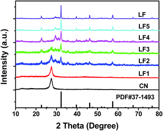
The XRD patterns of g-C3N4, LaFeO3 and LaFeO3/g-C3N4 heterojunction nanocomposites are presented in Fig. 1. The g-C3N4 sample exhibited two diffraction peaks at 13.2° and 27.5°, corresponding to (100) and (002) diffraction planes, respectively. All the diffraction peaks of LaFeO3 were indexed to an orthorhombic phase (PDF#37-1493), indicating the purity and high crystallinity of LaFeO3. After forming the LaFeO3/g-C3N4 heterojunction nanocomposites with g-C3N4, only the XRD pattern of 5%-LaFeO3/g-C3N4 was similar to that of g-C3N4. Other LaFeO3/g-C3N4 nanocomposites simultaneously maintained the features of pure g-C3N4 and LaFeO3. With the increase of LaFeO3 content in the nanocomposites, diffraction peaks originating from g-C3N4 were gradually decreased. These XRD results proved the formation of the LaFeO3/g-C3N4 composites.TEM images of the 5%-LaFeO3/g-C3N4 nanocomposites are shown in Fig. 2. The g-C3N4 exhibited a thin and irregular nanosheet structure with wrinkles (Fig. 2a).20 The LaFeO3 nanoparticles with a diameter of about 30 nm were distributed in g-C3N4 to form a heterostructure with interfacial contact. This heterostructure could effectively improve the photocatalytic activity by supplying plenty of reactive sites to adsorb reactant and capture charge carriers. The representative particle in the selected region displayed continuous lattice fringes with a d-spacing of 0.2480 nm, corresponding to the (201) planes of the orthorhombic phase of LaFeO3 (Fig. 2c–e).
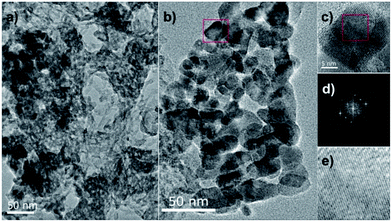 | ||
| Fig. 2 TEM images (a, b) and HRTEM micrograph (c) of the selected area image of 5%-LaFeO3/g-C3N4, with the fast Fourier transform (FTT) pattern (d) and the corresponding inverse FFT pattern (e). | ||
Fig. 3a displays the FTIR spectra of g-C3N4, LaFeO3 and LaFeO3/g-C3N4. The broad absorption peak centered at 3200 cm−1 and the peak at 1640 cm−1 in the spectra of g-C3N4 and LaFeO3/g-C3N4 were assigned to the stretching and bending vibrations of N–H. With the increase of LaFeO3 content in the LaFeO3/g-C3N4 nanocomposites, the intensities of these two absorption peaks were gradually decreased and ultimately disappeared. Fig. 3b shows the corresponding magnification of FTIR spectra in the range of 650 cm−1 to 1800 cm−1. The absorption at 810 cm−1 was derived from the breathing vibration of s-triazine. The absorption peaks at 1575, 1413, 1326 and 1249 cm−1 were ascribed to characteristic C–N stretching of the g-C3N4 heterocycles.20,27 The decrease of the intensities revealed the reduced content of g-C3N4. However, for 40%-LaFeO3/g-C3N4 and 60%-LaFeO3/g-C3N4, these characteristic absorption peaks had disappeared in the same way as for LaFeO3. Combined with the XRD results, these results suggested that the 5%-LaFeO3/g-C3N4, 10%-LaFeO3/g-C3N4 and 20%-LaFeO3/g-C3N4 samples contained two components of LaFeO3 and g-C3N4.
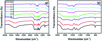 | ||
| Fig. 3 (a) FTIR spectra of g-C3N4, LaFeO3 and LaFeO3/g-C3N4 and (b) the corresponding magnification from 650 cm−1 to 1800 cm−1. | ||
Fig. 4a shows the XPS survey spectra of 5%-LaFeO3/g-C3N4, which proves the presence of carbon (C), iron (Fe), lanthanum (La), nitrogen (N), and oxygen (O), in the nanocomposite. Fig. 4b–f shows the corresponding high resolution spectra of the C 1s, N 1s, Fe 2p, La 3d and O 1s orbitals. The N 1s peak at 398.43 eV was a characteristic peak allocated to sp2 hybridized nitrogen (C![[double bond, length as m-dash]](https://www.rsc.org/images/entities/char_e001.gif) N–C).17,22 The peak at 399.96 eV was attributed to the tertiary nitrogen and amino groups with an H atom. In the C 1s spectra, two peaks at 284.82 and 287.98 eV were derived from contaminated carbon on the surface of LaFeO3/g-C3N4 sample and sp2 C atoms bonded to amino groups in the triazine cycles. The N 1s and C 1s spectra confirmed the presence of the g-C3N4. The peak of Fe 2p3/2 and Fe 2p1/2 at 711.1 and 724.9 eV, respectively, were assigned to the core level spectra of Fe3+ in its oxide form.28,29 Two La 3d peaks at 836.2 and 852.3 eV were identified as spin–orbit splitting of 3d5/2 and 3d3/2 of La3+, respectively, in the oxide.30 For O 1s spectra, only one peak at 531.6 eV was observed and was ascribed to the oxygen network in the perovskite lattice of LaFeO3. The binding energy of O 1s, Fe 2p and La 3d for 5%-LaFeO3/g-C3N4 shifted to higher values. However, the peaks of N 1s and C 1s shifted to lower binding energies. These shifts of binding energies demonstrated that g-C3N4 was covered closely on the surface of LaFeO3, and showed a strong chemical interaction between g-C3N4 and LaFeO3.22
N–C).17,22 The peak at 399.96 eV was attributed to the tertiary nitrogen and amino groups with an H atom. In the C 1s spectra, two peaks at 284.82 and 287.98 eV were derived from contaminated carbon on the surface of LaFeO3/g-C3N4 sample and sp2 C atoms bonded to amino groups in the triazine cycles. The N 1s and C 1s spectra confirmed the presence of the g-C3N4. The peak of Fe 2p3/2 and Fe 2p1/2 at 711.1 and 724.9 eV, respectively, were assigned to the core level spectra of Fe3+ in its oxide form.28,29 Two La 3d peaks at 836.2 and 852.3 eV were identified as spin–orbit splitting of 3d5/2 and 3d3/2 of La3+, respectively, in the oxide.30 For O 1s spectra, only one peak at 531.6 eV was observed and was ascribed to the oxygen network in the perovskite lattice of LaFeO3. The binding energy of O 1s, Fe 2p and La 3d for 5%-LaFeO3/g-C3N4 shifted to higher values. However, the peaks of N 1s and C 1s shifted to lower binding energies. These shifts of binding energies demonstrated that g-C3N4 was covered closely on the surface of LaFeO3, and showed a strong chemical interaction between g-C3N4 and LaFeO3.22
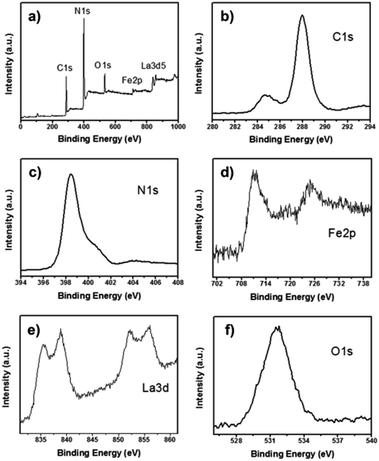 | ||
| Fig. 4 (a) Survey XPS spectra and high resolution spectra of C (b), N (c), Fe (d), La (e) and O (f) of 5%-LaFeO3/g-C3N4. | ||
The UV-vis DRS of g-C3N4, LaFeO3 and LaFeO3/g-C3N4 with different LaFeO3 contents are shown in Fig. 5a. Pure g-C3N4 displayed an absorption edge at 455 nm, corresponding to a band gap energy (Eg) of 2.73 eV (Fig. 5b), which was consistent with previous results found in the literature.31 LaFeO3 showed a strong light absorption in the range of 200 to 800 nm. LaFeO3/g-C3N4 samples had broader absorptions and longer absorption edge wavelengths than that of g-C3N4, which was attributed to the strong interaction between LaFeO3 and g-C3N4 in the heterostructures.
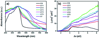 | ||
| Fig. 5 (a) UV-vis DRS spectra and (b) band gap energies of pure g-C3N4, LaFeO3 and LaFeO3/g-C3N4 heterojunctions. | ||
The band gap energies of g-C3N4, LaFeO3 and LaFeO3/g-C3N4 were calculated using the Tauc relationship. Fig. 5b shows the Tauc plots of (ahv)2 versus hv.32 The band gap energies of g-C3N4 and LaFeO3 were 2.73 and 1.92 eV, respectively. The Eg of LaFeO3 was slightly smaller than the reported values found in the literature (2.0 eV).33 The Eg values of LaFeO3/g-C3N4 with different LaFeO3 content from 5% to 60% were 2.69, 2.55, 2.45, 1.92 and 1.92 eV. These results indicated that the Eg reduced as the LaFeO3 content increased from 5% to 20%. However, the 40%-LaFeO3/g-C3N4 and 60%-LaFeO3/g-C3N4 had the same Eg values as pure LaFeO3. It was suggested that LaFeO3 and g-C3N4 had not formed the heterostructures in 40%-LaFeO3/g-C3N4 and 60%-LaFeO3/g-C3N4 samples efficiently, which was also demonstrated by the XRD and FTIR results. The most probable causes proposed are given next. In this work, 60% or 40% of g-C3N4 was heated with iron nitrate and lanthanum nitrate for 2 h at 450 °C to prepare the samples. This heat treatment procedure could give rise to volatilization of g-C3N4, which decreased the actual amounts of g-C3N4 in the samples. The relative higher LaFeO3 content and lack of g-C3N4 lead to self-agglomeration of LaFeO3, and consequently the heterostructures could not be formed efficiently.
The CB and VB edge positions of the g-C3N4 and LaFeO3 were calculated using the following two equations:
| EVB = X − Ee + 0.5Eg |
| ECB = EVB − Eg |
To test the photocatalytic activity of the LaFeO3/g-C3N4 heterojunctions, photocatalytic degradation of MB under 3 W LED irradiation was implemented. The absorption peak at 664 nm was selected to monitor the degradation of MB. As shown in Fig. 6a, only 3–10% of MB was degraded over the g-C3N4, LaFeO3 and 60%-LaFeO3/g-C3N4 under 3 W LED irradiation for 120 min. By comparison, the degradation rate of MB on the LaFeO3/g-C3N4 samples with 5%, 10% and 20% LaFeO3 was significantly enhanced. The 5%-LaFeO3/g-C3N4 heterojunction exhibited the highest photocatalytic activity, over which more than 95% of MB was degraded after irradiation for 120 min.
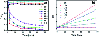 | ||
| Fig. 6 (a) Photocatalytic degradation of MB over g-C3N4, LaFeO3 and LaFeO3/g-C3N4 under 3 W LED irradiation and (b) corresponding second-order kinetics plots. | ||
The second-order kinetics model was used to fit the photocatalytic degradation data. The results are shown in Fig. 6b. The 5%-LaFeO3/g-C3N4 heterojunction nanocomposite exhibited the highest photocatalytic activity. Its second-order reaction rate constant was around 49.7 and 86.9 times more than pure g-C3N4 and LaFeO3 (Fig. 7), respectively. On the basis of the previous XRD, FTIR and DRS measurements, this photocatalytic degradation result demonstrated that LaFeO3 and g-C3N4 had effectively formed the heterojunction composites. The strong interfacial interaction between LaFeO3 and g-C3N4 in the composites could improve the transfer of the photoproduced charge and enhance their photocatalytic performances.17 This strong interfacial interaction between LaFeO3 and g-C3N4 in the composites was investigated using simple mechanical mixing of LaFeO3 and g-C3N4 in the same ratio as the composites and then using it to degrade MB under 3 W LED irradiation (curve LF6 in Fig. 6a). The photocatalytic activity of the 5%-LaFeO3/g-C3N4 heterojunction nanocomposite was much higher than that of a simple mechanical mixture. This result indicated the formation of intimately contacted interfaces in the heterojunction nanocomposite, which is also displayed in the TEM images (Fig. 2).
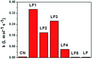 | ||
| Fig. 7 The second-order reaction rate constants of photocatalytic degradation of MB on g-C3N4, LaFeO3 and LaFeO3/g-C3N4 under 3 W LED irradiation. | ||
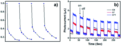
The stability of the 5%-LaFeO3/g-C3N4 heterojunction nanocomposite was studied by recycling 5%-LaFeO3/g-C3N4 under the same photocatalytic degradation conditions for degrading MB. As shown in Fig. 8a, after four recycles, no significant changes were observed. This result proved that the LaFeO3/g-C3N4 nanocomposites possessed a relatively high stability for photocatalytic degradation of MB.
These photocatalytic degradation results revealed that the intimately contacted interfaces between LaFeO3 and g-C3N4 in the heterojunction nanocomposite resulted in the high transfer and separation of photoproduced charges at the interface of the heterostructures.17 This assumption was further confirmed by the transient photocurrent responses of the g-C3N4, LaFeO3 and 5%-LaFeO3/g-C3N4. The photocurrent–time (I–t) curves were obtained by intermittently cutting off the visible light irradiation (Fig. 8b). The photocurrent value of 5%-LaFeO3/g-C3N4 was about two times higher than pure LaFeO3 and g-C3N4. This was attributed to the efficient separation of the photoproduced charges in space and consequently reduced the carrier recombination.
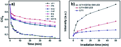
To investigate which type of reactive species, including hydrogen peroxide (H2O2), h+, e−, ˙OH and ˙O2−, were involved in the photocatalytic degradation of MB over the 5%-LaFeO3/g-C3N4, ammonium oxalate (AO), EDTA-2Na, isopropanol (IPA), NO3−, catalase (CAT) and benzoquinone (BQ) were added to the degradation solutions.34 AO and EDTA-2Na were the scavenger of h+, IPA was the scavenger of ˙OH radicals, NO3− acted as the e− scavenger, CAT was the H2O2 scavenger, and BQ acted as the ˙O2− radical scavenger. As shown in Fig. 9a, no obvious changes were found when NO3− and CAT were added to the solutions, indicating that e− and H2O2 were not the active species in the photocatalytic degradation of MB. The addition of IPA significantly decreased the photodegradation rate. It was revealed that ˙OH radicals were the dominant species for MB photodegradation. As shown in Fig. 9a, BQ also decreased the photodegradation rate slightly, demonstrating the minor role of ˙O2−. However, in the presence of AO and EDTA-2Na, the photocatalytic degradation rate was remarkably increased. Only a few reports in the literature have reported the increase of photodegradation rate by the addition of EDTA-2Na in to the solution.35,36 It was considered that the addition of EDTA-2Na trapped the h+ and promoted the separation rate of the e−/h+ pairs, and consequently more ˙OH radicals were achieved. Therefore the photodegradation activity was improved.
To confirm the increase of ˙OH radicals in the presence of EDTA-2Na, TA was used to react with ˙OH to form 2-hydroxyterephthalic acid (HTA), which possessed strong fluorescence.17,37 The results of the HTA experiment are shown in Fig. 9b. It shows that the peak intensities of HTA were enhanced significantly when EDTA-2Na was added in to the degradation solution. Fig. 9b also revealed that more ˙OH radicals were generated under 3 W LED irradiation than were produced under indoor light irradiation. Different dosages of EDTA-2Na were added to the degradation solution to test the influence of EDTA-2Na concentration on the photodegradation of MB over the 5%-LaFeO3/g-C3N4. The results are shown in Fig. 10. It indicated that by increasing the amount of EDTA-2Na, the photocatalytic degradation rate was enhanced dramatically. More than 95% of MB was degraded by adding 25 mg EDTA-2Na to 100 mL MB solution and then irradiated with a 3 W LED for 15 min.
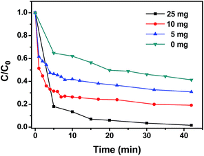 | ||
| Fig. 10 The influence of different dosages of EDTA-2Na on the photodegradation of MB over the 5%-LaFeO3/g-C3N4 with 3 W LED irradiation. | ||
The photocatalytic H2 evolution activity of g-C3N4, LaFeO3 and LaFeO3/g-C3N4 heterojunctions in aqueous solution containing 10 vol% TEOA under 300 W Xe lamp irradiation were studied. As shown in Fig. 11, the H2 evolution rate was negligible over the pure LaFeO3, g-C3N4, 40%-LaFeO3/g-C3N4 and 60%-LaFeO3/g-C3N4. The photocatalytic H2 evolution activity of LaFeO3/g-C3N4 containing 5, 10 and 20 wt% of LaFeO3 was remarkably enhanced. The 5%-LaFeO3/g-C3N4 heterojunction nanocomposite in particular had a maximum H2 evolution rate of 158 μmol g−1 h−1.
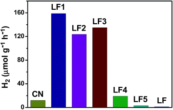 | ||
| Fig. 11 The photocatalytic hydrogen evolution activity under 300 W Xe lamp irradiation over g-C3N4, LaFeO3 and LaFeO3/g-C3N4 nanocomposites. | ||
The recyclability of 5%-LaFeO3/g-C3N4 nanocomposites was tested using five cycles of photocatalytic H2 evolution under identical reaction conditions. As shown in Fig. 12, 450 μmol of H2 was generated after irradiation for 3 h under visible light in the first run. The amount of H2 was finally reduced to 395 μmol in the fifth run. Only 12.2% H2 production was lost after the fifth photocatalytic experiment. The results indicated that 5%-LaFeO3/g-C3N4 was quite stable for photocatalytic H2 production under visible light irradiation.
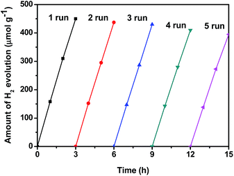 | ||
| Fig. 12 Recyclability of the H2 evolution test over 5%-LaFeO3/g-C3N4 nanocomposites under 300 W Xe lamp irradiation. | ||
On the basis of the results of the ˙OH trapping experiments, the potential route of chemical reactions responsible for the generation of ˙OH was determined. The photocatalytic procedure over LaFeO3/g-C3N4 was in accordance with the features of a Z-scheme photocatalysis system. Under visible light irradiation, both LaFeO3 and g-C3N4 were excited to obtain photoinduced electron and hole pairs. The photoexcited electrons of LaFeO3 and g-C3N4 transited from the VB to the CB and the holes were left on the VB. The electrons from the CB of LaFeO3 transferred to the VB of g-C3N4 using the solid–solid intimately contacted interfaces, where the electrons and holes were recombined and thus improved the separation of the photogenerated electrons and holes of g-C3N4. Then the excited electrons reduced O2 adsorbed on the surface of g-C3N4 to produce ˙O2−. The ˙O2− reacted with H2O to achieve ˙OH. Finally, MB was degraded by ˙OH and ˙O2−. As shown in Fig. 13, the CB edge potential of LaFeO3 was more positive than the standard redox potential of H+/H2, which cannot reduce H+ to form H2. H+ was subsequently reduced by the CB electrons of g-C3N4 to generate H2. The holes on the VB of LaFeO3 reacted with TEOA or EDTA-2Na (as the sacrificial agent) to promote the separation of the photogenerated electrons and holes, which resulted in the improvement of the photocatalytic performance.
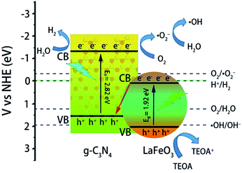 | ||
| Fig. 13 Possible photocatalytic degradation of MB and H2 evolution mechanism over LaFeO3/g-C3N4 heterojunctions under visible light irradiation. | ||
The photocatalytic H2 evolution activity was consistent with the photodegradation rate of MB. The excess LaFeO3 (above 20 wt% in the nanocomposite) decreased the H2 evolution rate. Fig. 13 clearly shows the correlation between the higher H2 evolution rate and higher amount of ˙OH generated over the LaFeO3/g-C3N4 heterojunction nanocomposites. It possessed the features of a Z-scheme system. Under visible light irradiation, both LaFeO3 and g-C3N4 were excited to obtain photoinduced electron and hole pairs. The photoexcited electrons of LaFeO3 and g-C3N4 transited from the VB to the CB and the holes were left on the VB. The electrons from the CB of LaFeO3 were transferred to the VB of g-C3N4 by the solid–solid intimately contacted interfaces, where the electrons and holes were recombined and thus improved the separation of the photogenerated electrons and holes of g-C3N4. Then the excited electrons on the CB of g-C3N4 efficiently generated the ˙OH. Meanwhile, the improved separation of the photogenerated electron and hole of g-C3N4 of this Z-scheme system also efficiently enhanced the H2 evolution rate. The holes on the VB of LaFeO3 reacted with TEOA or EDTA-2Na (as the sacrificial agent) to promote the separation of photogenerated electrons and holes, which resulted in the improvement of the photocatalytic performance.
The results revealed that the optimum concentration of LaFeO3 was 5 wt% for the maximum photocatalytic H2 evolution and photodegradation rate. Too high a content of LaFeO3 was adverse for the efficacious formation of heterojunction nanocomposites and also gave reduced photocatalytic H2 evolution and photodegradation rate. LaFeO3 and g-C3N4 did not form efficiently the heterostructures in 40%-LaFeO3/g-C3N4 and 60%-LaFeO3/g-C3N4 samples, which was demonstrated by the XRD and FTIR results. This led to the 40%-LaFeO3/g-C3N4 and 60%-LaFeO3/g-C3N4 samples having a much lower degradation rate.
5%-LaFeO3/g-C3N4, 10%-LaFeO3/g-C3N4 and 20%-LaFeO3/g-C3N4 formed intimately contacted interfaces in the nanocomposites, which had higher degradation rate. Among these nanocomposites, 5%-LaFeO3/g-C3N4 gave the optimum results for MB degradation. The absorption edges of g-C3N4, LaFeO3 and LaFeO3/g-C3N4 are compared in Fig. 5a. This revealed that LaFeO3/g-C3N4 samples had broader absorptions and longer absorption edge wavelengths than that of g-C3N4. The absorption intensity of 5%-LaFeO3/g-C3N4 in the visible light region was much higher than that of 10%-LaFeO3/g-C3N4 and 20%-LaFeO3/g-C3N4, which indicated that the 5%-LaFeO3/g-C3N4 produced a greater amount of photogenerated electron–hole pairs.34 Based on the UV-vis DRS spectra, XRD and FTIR results, it could be deduced that the greater amount of photogenerated electron–hole pairs and the efficient charge separation of the Z-scheme photocatalytic system gave the 5%-LaFeO3/g-C3N4 heterojunction, the highest MB degradation and H2 evolution rate.
4. Conclusion
The new type of LaFeO3/g-C3N4 heterostructures were successfully prepared using a two-step method. It possessed the features of a Z-scheme photocatalysis system. The photoexcited electrons on the CB of LaFeO3 were transferred to the VB of g-C3N4 by the solid–solid intimately contacted interfaces, where the electrons and holes were recombined and thus improved the separation of photogenerated electrons and holes of g-C3N4. LaFeO3 and g-C3N4 also effectively formed intimately contacted interfaces. This strong interfacial interaction could improve the transfer photoproduced charge and enhance their photocatalytic performances. Thus, LaFeO3/g-C3N4 heterostructures had a higher H2 evolution rate and a higher amount of ˙OH than pure LaFeO3 and g-C3N4. The construction of LaFeO3/g-C3N4 heterostructures was demonstrated to be the effective strategy to improve the photocatalytic property. The 5%-LaFeO3/g-C3N4 exhibited the highest photodegradation and water splitting rate. More than 95% of MB was degraded after 15 min in the presence of 25 mg EDTA-2Na in 100 mL of MB solution with irradiation using a 3 W LED. The photogenerated ˙OH radicals were the main oxidative species for the degradation of MB. Its second-order reaction rate constant was about 49.7 and it was 86.9 times more than that of pure g-C3N4 and LaFeO3. The 5%-LaFeO3/g-C3N4 heterojunction nanocomposite had a maximum H2 evolution rate of 158 μmol g−1 h−1. This research shows an easy approach to manufacturing LaFeO3/g-C3N4 heterojunction nanocomposites to promote the exploitation of solar energy.Conflicts of interest
There are no conflicts to declare.Acknowledgements
This research was supported by the Science and Technology Foundation of Guizhou, China (No. [2013] 2044, No. [2015] 7338, No. [2016] 7366), and the Science and Technology Foundation of Guiyang, China (No. [20161001] 001).Notes and references
- S. Cao, J. Low, J. Yu and M. Jaroniec, Adv. Mater., 2015, 27, 2150 CrossRef CAS PubMed.
- A. Fujishima and K. Honda, Nature, 1972, 238, 37 CrossRef CAS PubMed.
- J. Yu, J. Low, W. Xiao, P. Zhou and M. Jaroniec, J. Am. Chem. Soc., 2014, 136, 8839 CrossRef CAS PubMed.
- X. Wang, M. Liao, Y. Zhong, J. Y. Zheng, W. Tian, T. Zhai, C. Zhi, Y. Ma, J. Yao, Y. Bando and D. Golberg, Adv. Mater., 2012, 24, 3421 CrossRef CAS PubMed.
- W. C. Huang, L. M. Lyu, Y. C. Yang and M. H. Huang, J. Am. Chem. Soc., 2012, 134, 1261 CrossRef CAS PubMed.
- Z. Zou, J. Ye, K. Sayama and H. Arakawa, Nature, 2001, 414, 625 CrossRef CAS PubMed.
- M. Liu, W. You, Z. Lei, G. Zhou, J. Yang, G. Wu, G. Ma, G. Luan, T. Takata, M. Hara, K. Domen and C. Li, Chem. Commun., 2004, 2192 RSC.
- Y. Hu, X. Gao, L. Yu, Y. Wang, J. Ning, S. Xu and X. W. Lou, Angew. Chem., Int. Ed., 2013, 52, 5636 CrossRef CAS PubMed.
- X. Zhou, Q. Xu, W. Lei, T. Zhang, X. Qi, G. Liu, K. Deng and J. Yu, Small, 2014, 10, 674 CrossRef CAS PubMed.
- Y. Wang, X. Wang and M. Antonietti, Angew. Chem., Int. Ed., 2012, 51, 68 CrossRef CAS PubMed.
- E. Kroke, Angew. Chem., Int. Ed., 2014, 53, 11134 CrossRef CAS PubMed.
- A. Thomas, A. Fischer, F. Goettmann, M. Antonietti, J. Müller, R. Schlöglb and J. M. Carlssonc, J. Mater. Chem., 2008, 18, 4893 RSC.
- Y. Zheng, J. Liu, J. Liang, M. Jaroniecc and S. Z. Qiao, Energy Environ. Sci., 2012, 5, 6717 CAS.
- J. Zhang, X. Chen, K. Takanabe, K. Maeda, K. Domen, J. D. Epping, X. Fu, M. Antonietti and X. Wang, Angew. Chem., Int. Ed., 2010, 49, 441 CrossRef CAS PubMed.
- Y. Zheng, L. Lin, X. Ye, F. Guo and X. Wang, Angew. Chem., Int. Ed., 2014, 53, 11926 CrossRef CAS PubMed.
- G. Liu, P. Niu, C. Sun, S. C. Smith, Z. Chen, G. Q. Lu and H. Cheng, J. Am. Chem. Soc., 2010, 132, 11642 CrossRef CAS PubMed.
- J. Fu, Y. Tian, B. Chang, F. Xi and X. Dong, J. Mater. Chem., 2012, 22, 21159 RSC.
- S. Yang, W. Zhou, C. Ge, X. Liu, Y. Fang and Z. Li, RSC Adv., 2013, 3, 5631 RSC.
- W. Tian, Q. Shen, N. Li and J. Zhou, RSC Adv., 2016, 6, 25568 RSC.
- D. Jiang, J. Li, C. Xing, Z. Zhang, S. Meng and M. Chen, ACS Appl. Mater. Interfaces, 2015, 7, 19234 CAS.
- C. Zhao, G. Tan, J. Huang, W. Yang, H. Ren and A. Xia, ACS Appl. Mater. Interfaces, 2015, 7, 23949 CAS.
- F. Li, S. Liu, Y. Xue, X. Wang, Y. Hao, J. Zhao, R. Liu and D. Zhao, Chem.–Eur. J., 2015, 21, 10149 CrossRef CAS PubMed.
- J. Yang, R. Hu, W. Meng and Y. Du, Chem. Commun., 2016, 52, 2620 RSC.
- P. Li, X. Hu, L. Zhang, H. Dai and L. Zhang, Nanoscale, 2011, 3, 974 RSC.
- X. Ren, H. Yang, S. Gen, J. Zhou, T. Yang, X. Zhang, Z. Cheng and S. Sun, Nanoscale, 2016, 8, 752 RSC.
- Q. Yu, X. Meng, T. Wang, P. Li, L. Liu, K. Chang, G. Liu and J. Ye, Chem. Commun., 2015, 51, 3630 RSC.
- L. M. Sun, Y. Qi, C. J. Jia, Z. Jin and W. L. Fan, Nanoscale, 2014, 6, 2649 RSC.
- M. Markova-Velichkova, T. Lazarova, V. Tumbalev, G. Ivanov, D. Kovacheva, P. Stefanov and A. Naydenov, Chem. Eng. J., 2013, 231, 236 CrossRef CAS.
- H. Wu, R. Hu, T. Zhou, C. Li, W. Meng and J. Yang, CrystEngComm, 2015, 17, 3859 RSC.
- S. Thirumalairajan, K. Girija, N. Y. Hebalkar, D. Mangalaraj, C. Viswanathan and N. Ponpandian, RSC Adv., 2013, 3, 7549 RSC.
- H. Zhang, L. Guo, L. Zhao, B. Wan and Y. Yang, J. Phys. Chem. Lett., 2015, 6, 958 CrossRef CAS PubMed.
- H. Liu, Z. Jin, Z. Xu, Z. Zhang and D. Ao, RSC Adv., 2015, 5, 97951 RSC.
- L. Jing, Y. Qu, H. Su, C. Yao and H. Fu, J. Phys. Chem. C, 2011, 115, 12375 CAS.
- H. Li, Y. Liu, X. Gao, C. Fu and X. Wang, ChemSusChem, 2015, 8, 1189 CrossRef CAS PubMed.
- S. Hu, L. Ma, J. You, F. Li, Z. Fan, F. Wang, D. Liu and J. Gui, RSC Adv., 2014, 4, 21657 RSC.
- J. Zhang, S. Hu and Y. Wang, RSC Adv., 2014, 4, 62912 RSC.
- R. Marschall, A. Mukherji, A. Tanksale, C. Sun, S. C. Smith, L. Wang and G. Q. Lu, J. Mater. Chem., 2011, 21, 8871 RSC.
| This journal is © The Royal Society of Chemistry 2017 |

