
 Open Access Article
 This Open Access Article is licensed under a
 Creative Commons Attribution 3.0 Unported Licence
Hierarchical porous carbon spheres constructed from coal as electrode materials for high performance supercapacitors†
Mingxi Guo,
Jixi Guo *,
Fenglian Tong,
Dianzeng Jia*,
Wei Jia,
Jingbin Wu,
Luxiang Wang and
Zhipeng Sun
*,
Fenglian Tong,
Dianzeng Jia*,
Wei Jia,
Jingbin Wu,
Luxiang Wang and
Zhipeng Sun
Key Laboratory of Energy Materials Chemistry, Ministry of Education, Key Laboratory of Advanced Functional Materials, Institute of Applied Chemistry, Xinjiang University, Autonomous Region, Urumqi 830046, Xinjiang, P. R. China. E-mail: jxguo1012@163.com; jdz0991@gmail.com; Fax: +86-991-8588883; Tel: +86-991-8583083
First published on 22nd September 2017
Abstract
Hierarchical porous carbon spheres (PCS) are prepared by a simple one-pot spray pyrolysis of coal oxide solution without any further activation process. The specific surface area and total pore volume of the resultant carbon spheres are increased significantly with the increase of spray pyrolysis temperature. When evaluated as electrode materials for supercapacitors in 6 M KOH electrolyte, the PCS exhibits a high specific capacitance 227 F g−1 at a current density of 1 A g−1 and outstanding cycling stability after 10![[thin space (1/6-em)]](https://www.rsc.org/images/entities/char_2009.gif) 000 charge/discharge cycles at a current density of 2 A g−1. In symmetric supercapacitor, the specific capacitance of the sample PCS-8 is 180 F g−1 at a current density of 0.2 A g−1 and has excellent rate capability. The proposed strategy offers a facile and green method to produce porous carbon spheres from coal, and has potential application in energy storage.
000 charge/discharge cycles at a current density of 2 A g−1. In symmetric supercapacitor, the specific capacitance of the sample PCS-8 is 180 F g−1 at a current density of 0.2 A g−1 and has excellent rate capability. The proposed strategy offers a facile and green method to produce porous carbon spheres from coal, and has potential application in energy storage.
1. Introduction
Supercapacitors have been considered as one of the most promising energy-storage devices that can meet the development needs of future society due to their high efficiencies, high power/energy densities, long cycling stabilities, green/safe operation, etc.1–3 Supercapacitors can be classified into two major categories based on the energy storage mechanism: electrical double layer capacitors (EDLCs) and pseudocapacitor.4 Generally,5,6 energy stored in an EDLCs is proportional to the electrostatic charge accumulated at the electrode/electrolyte interface; pseudocapacitors store energy via the faradaic reactions that occur between the electrode materials and electrolyte. Thus, EDLCs electrode materials should have large specific surface area (SSA) and match with appropriate pore structure for charge accumulation, electrolyte wetting and rapid ionic transportation.7It is well known that carbon materials, such as activated carbon (AC), carbon fibers, carbon nanotubes (CNT), and graphene, are conventionally used as energy storage materials, due to their advantages such as large SSA, good electronic conductivity, and high chemical stability.8–12 Carbon materials for EDLCs have been well reviewed recently, and mainly focus on porous structure optimization, morphology control, and surface modification. The hierarchical porous carbon materials have been widely concerned, because of it has abundant micropores, mesopores, and macropores, which can provide a large accessible surface area, rapid ionic transportation and leading to a large capacitance and high energy density.13 How to use high quality, green and cheap carbon sources to prepare porous carbon materials has become a hot spot of current research. In all carbon sources, coal is cheap and abundant naturally occurring material compared to other derivative source materials, such as graphite, methane or other hydrocarbons.14,15 Therefore, how to find a simple and green method to promote the efficient utilization of coal resources has been paid more and more attentions from all over the word. Usually, coal based activated carbon prepared by carbonization and activation. Wilson and his co-workers first reported the prepared of C60,16 C70, and CNTs17 from coal by using the arc-discharge method with coal-based carbon as the evaporation anode. Kazuto Hatakeyama group founded that the coal is a promising carbon-based proton conductor by simple liquid-phase oxidation.18 Over the past decade, Qiu and his co-workers have intensively investigated the possibility and feasibility of preparing various carbon nanomaterials (AC, CNT, carbon dot and graphene etc.) from Chinese coal.19–23 Recently, in order to realize the high added value of coal, the coal was modified by liquid phase oxidation, and the modified coal as carbon precursor to prepare carbon fibers in our groups.24–27 The coal derived carbon fibers exhibit excellent electrochemical performance and organic matter absorption.
In this paper, we report a simple method for the preparation of coal based porous carbon spheres (PCS). Firstly, coal was treated by using a mixture of concentrated sulfuric acid and nitric acid, and the obtained coal oxide can be dissolved in aqueous solution. Then, the PCS was prepared by a simple one-pot spray pyrolysis method without further activation using coal oxide solution as carbon precursor. The detailed formation mechanism of coal based porous carbon spheres was studied. The PCS has been evaluated as EDLCs electrode in KOH solution and its remarkable capacitive performance has been demonstrated in this work.
2. Experimental
Coal was obtained from Heishan, Xinjiang, China. Other chemicals were analytical grade and were used as received without further purification. The industrial elemental analysis of raw coal components was studied in our previous paper.242.1 Coal based porous carbon sphere
Coal oxide was prepared according to the reported method previously.24,27 The raw coal was oxidized by concentrated sulfuric acid and nitric acid treatment, and the coal oxide can easily dissolve in alkaline water. Then, the coal oxide (0.8 g) was added into distilled water (40 mL) followed by stir and then added sodium dodecyl benzene sulfonate (SDBS) until the solution reached a neutral pH value. The coal based carbon spheres were prepared directly by ultrasonic spray pyrolysis from the coal based aqueous solution with different temperature. The spray pyrolysis system consisted of droplet generator, quartz reactor, and powder collector. 2 MHz ultrasonic spray generator was used to generate a large quantity of droplets. A quartz reactor with length of 450 mm and a diameter of 50 mm was used. The flow rate of the nitrogen gas used as carrier gas was 0.5 L min−1. The droplets evaporated, and decomposed in the quartz reactor, and the black powders were collected. The coal based carbon spheres with different pyrolysis temperature (700 °C, 800 °C, 900 °C, 1000 °C) were denoted as PCS-7, PCS-8, PCS-9, and PCS-10.2.2 Characterization
The infrared spectroscopy study was carried out using a Bruker VERTEX 70 Fourier transform infrared (FT-IR) spectrometer in a range of wavenumbers from 400 to 4000 cm−1. Raman spectroscopy was performed on a Bruker SENTERRA dispersive Raman microscope using a 532 nm laser. Powder X-ray diffraction (XRD) measurements were conducted on a Bruker D8 Advance Diffraction diffractometer in the 2 theta range from 5° to 80°, with Cu Kα radiation (λ = 0.15405 nm) at 40 kV and 40 mA. Field emission scanning electron microscopy (FE-SEM) images were obtained by using a Hitachi S-4800 microscope at an accelerating voltage of 5 kV. Transmission electron microscopy (TEM) images of the products were obtained on a JEOL JEM-2100F electron microscope with an accelerating voltage of 200 kV. The Brunauer–Emmett–Teller (BET) and Barrett–Joyner–Halenda (BJH) measurements were performed on a Micromeritics ASAP 2020 surface area and porosity analyzer.2.3 Electrochemical characterization
The electrochemical experiments were carried out using a three-electrode system under ambient conditions. A platinum slice was used as the counter electrode and the saturated calomel electrode (SCE) was served as the reference electrodes. The working electrode was prepared by casting a mixture of 85 wt% active material, 10 wt% acetylene black and 5 wt% polytetrafluoroethylene, and dispersed in ethanol to obtain a slurry, which was then coated onto the nickel foam current collectors (1 cm × 1 cm) with a spatula. Finally, the as-fabricated electrodes were dried at 60 °C for 12 h. The two-electrode system was measured by assembling a symmetrical capacitor. Cyclic voltammetry (CV), galvanostatic charge–discharge (GCD), and electrochemical impedance spectroscopy tests were measured on a CHI660D electrochemical workstation (Chenhua, Shanghai, China) in 6 M KOH electrolyte at room temperature. The cycling performance of the electrode was evaluated on a Land battery measurement system (CT2001A, Wuhan LAND electronics Co., Ltd).3. Results and discussion
The synthesis process of the PCS using the spray pyrolysis is illustrated as shown in Scheme 1. Firstly, the raw coal was oxidized by concentrated sulfuric acid and nitric acid treatment. In the process of acid treatment, the mineral component of raw coal was eliminated. The XRD of raw coal and oxidized coal were studied in our previous article.24 The morphology of raw coal and oxidized coal are shown in Fig. S1.† They have a random particle size distribution. The coal oxide can easily dissolve in alkaline water, which due to the surface of acid treated coal introduced into a large number of functional groups (–OH, –NH2, –C![[double bond, length as m-dash]](https://www.rsc.org/images/entities/char_e001.gif) O, –NO2 and –SO3H) (Fig. S2†).24 Secondly, droplets containing coal oxide is formed by the ultrasonic nebulizer. Fast drying and decomposition of droplets produced coal based porous carbon spheres by ultrasonic spray pyrolysis with different temperature. Compared with the acid treated coal (Fig. S2†), the functional groups on the surface of PCS was decreased or weaken due to high-temperature pyrolysis (Fig. S3†). PCS-7 only has –OH (3450 cm−1), –CO (1600 cm−1), –COO– (1380 cm−1), and R–OH (618 cm−1) functional groups (Fig. S3(a)†). The functional groups on the surface of PCS was disappear, split or weaken with the increase of pyrolysis temperature. When the pyrolysis temperature at 800 °C, the peak at 1600 cm−1 start appeared split peaks (1576 cm−1 (–CC)), and the peak intensity compared with 3450 cm−1 (–OH) was weakened (Fig. S3(b)†). This phenomenon shows that at the beginning of 800 °C, most of the aromatic group began to break, the number of rings of aromatic nucleus increase. The condensation of aromatic nucleus occurred, the lamellar orientation of graphite crystallites was adjusted. With the increase of pyrolysis temperature, the peak intensity of –CC and –CO relative to –OH peak became more weak, and the split peak at 1600 cm−1 became more obvious (Fig. S3(c and d)†). In other words, with the increase of pyrolysis temperature, the cracking degree of macromolecular aromatic group in coal is more serious, the lamellar orientation of graphite crystallites is more orderly, and the degree of graphite is higher.
O, –NO2 and –SO3H) (Fig. S2†).24 Secondly, droplets containing coal oxide is formed by the ultrasonic nebulizer. Fast drying and decomposition of droplets produced coal based porous carbon spheres by ultrasonic spray pyrolysis with different temperature. Compared with the acid treated coal (Fig. S2†), the functional groups on the surface of PCS was decreased or weaken due to high-temperature pyrolysis (Fig. S3†). PCS-7 only has –OH (3450 cm−1), –CO (1600 cm−1), –COO– (1380 cm−1), and R–OH (618 cm−1) functional groups (Fig. S3(a)†). The functional groups on the surface of PCS was disappear, split or weaken with the increase of pyrolysis temperature. When the pyrolysis temperature at 800 °C, the peak at 1600 cm−1 start appeared split peaks (1576 cm−1 (–CC)), and the peak intensity compared with 3450 cm−1 (–OH) was weakened (Fig. S3(b)†). This phenomenon shows that at the beginning of 800 °C, most of the aromatic group began to break, the number of rings of aromatic nucleus increase. The condensation of aromatic nucleus occurred, the lamellar orientation of graphite crystallites was adjusted. With the increase of pyrolysis temperature, the peak intensity of –CC and –CO relative to –OH peak became more weak, and the split peak at 1600 cm−1 became more obvious (Fig. S3(c and d)†). In other words, with the increase of pyrolysis temperature, the cracking degree of macromolecular aromatic group in coal is more serious, the lamellar orientation of graphite crystallites is more orderly, and the degree of graphite is higher.
 | ||
| Scheme 1 Schematic diagram of the formation of coal based hierarchical porous carbon spheres. | ||
The XRD patterns of the powders prepared directly by spray pyrolysis from coal based solution at various pyrolysis temperatures are shown in Fig. S4(A).† The diffraction peaks of all samples exhibit the wide (002) and (100) peaks of graphitic carbon around 26° and 42°, which are characteristic of amorphous carbon frameworks. With the increase of pyrolysis temperature, the peaks of (002) PCS become wide and shift to a relatively small angle. It can be inferred that the interlayer spacing d002 and the degree of graphite were increased with increase of pyrolysis temperature. Notability, there is a wide peak below 20 degree in PCS-10. This means that the product was pyrolyzed and significantly oxidized at higher temperature. The results are well consistent with FT-IR analysis.
The order and graphitization degree of the materials were studied by Raman spectroscopy (Fig. S4(B)†).28 The peak at 1359 cm−1 (D-band) is associated with the vibration of carbon atoms with dangling bonds in the plane termination of disordered graphite. The peak at 1593 cm−1 (G-band) corresponds to an E2g mode of hexagonal graphite and is related to the vibration of sp2-hybridized carbon atoms in a graphite layer. The intensity ratio of the D peak to the G peak, denoted as ID/IG, indicates the disorder degree of the carbon material. The higher the ratio, the lower the degree of the graphitic content. Fig. S4(B)† shows Raman spectra of PCS-7, PCS-8, PCS-9, and PCS-10, and the ID/IG ratios for them are 0.79, 0.94, 0.91 and 0.89, respectively. It can be inferred from intensity ratio that the crystal structure of carbon had been gradually destroyed with the increase of pyrolysis temperature, and the degree of graphite were increased from 800 °C, which is consistent with the results of FT-IR and XRD analysis.
The microstructure and morphology of the carbon spheres was investigated by electron microscopic (Fig. 1). From FE-SEM, uniform spheres with diameters distribution from 500–1000 nm can be observed. The surface microcosmic structure of the PCS-7 exhibit smooth (inset of Fig. 1(a)), the spherical surface of the PCS-8 starts to appear defects (inset of Fig. 1(c)). With the increase of pyrolysis temperature, the PCS-10 spherical samples have a serious etching phenomenon (Fig. 1(g)). These phenomena show that with the increase of ultrasonic spray pyrolysis temperature, the spherical surface of sample becomes more roughly. This is mainly due to the thermal decomposition of coal and the activation of water vapor intensified with the increase of pyrolysis temperature. From TEM, we know that the PCS-7 exhibits regular and smooth surface morphology (Fig. 1(b)). And with the increase of pyrolysis temperature, the surface of the PCS-8 sample has a small amount of holes (Fig. 1(d)), the surface of the PCS-9 becomes rough, and the edges become loose (Fig. 1(f)). The PCS-10 has obvious porous structure (Fig. 1(h)). The results of TEM is well integrated with the results of SEM analyses. In short, with the increase of pyrolysis temperature, the spherical surface of samples becomes more roughly, and the pore structure of samples turns more and more abundant.
 | ||
| Fig. 1 FE-SEM and TEM images of PCS with different pyrolysis temperature (a, b) PCS-7, (c, d) PCS-8, (e, f) PCS-9, (g, h) PCS-10. | ||
The specific surface area and pore size distribution of PCS were investigated by N2 adsorption–desorption measurements. As shown in Fig. 2(a), the samples PCS-7 and PCS-8 exhibit the combined type I/IV adsorption–desorption isotherms and the PCS-9 and PCS-10 are typical type IV curves according to the international union of pure and applied chemistry (IUPAC) classification. There is a N2 adsorbed volume increase with the increase of pyrolysis temperature at a very low relative pressure (P/P0 = 0 ∼ 0.01), which shows that all sample have micropores, and the PCS-10 contains larger. The hysteresis loops at the relative pressure between 0.4 and 0.9 of all sample, which indicates the presence of mesoporous. But the PCS-9 has the biggest hysteresis loop, this means that it has a large fraction of mesopores. The hysteresis loop at high relative pressure region (P/P0 > 0.9) can be seen obviously in all samples, which might be mainly ascribed to the internal macropores. The hierarchical pore structure of carbon spheres was confirmed by their corresponding pore size distribution curves (Fig. 2(b)). And the porosity parameters for all carbon spheres are summarized in Table 1. The BET specific surface area, the total pore volume, and the volume of micropores increase with the increasing of the pyrolysis temperature. This should be attributed to carbonization and steam activation of coal during the ultrasonic spray pyrolysis.
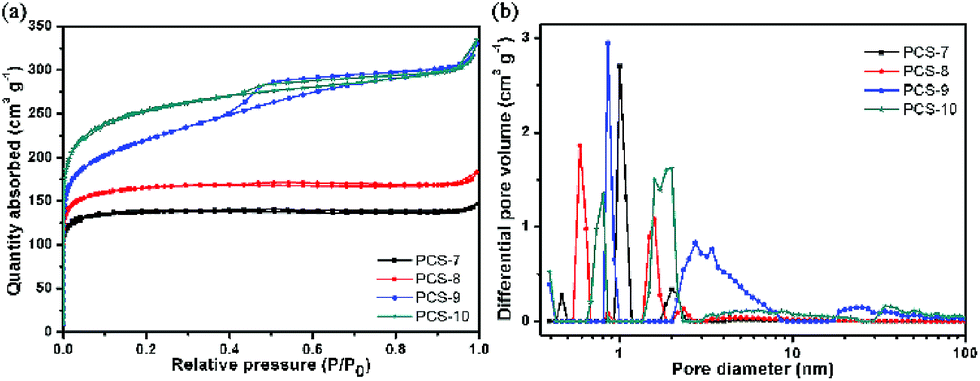 | ||
| Fig. 2 (a) Nitrogen adsorption/desorption isotherms at 77 K and (b) pore size distribution curves of porous carbon spheres. | ||
| Sample | SBETa (m2 g−1) | Vtotalb (cm3 g−1) | Vmesoc (cm3 g−1) | Vmicrod (cm3 g−1) | Dape (nm) |
|---|---|---|---|---|---|
| a SBET: specific surface area calculated by the BET method.b Vtotal: total pore volume at P/P0 = 0.99.c Vmeso: volume of mesopore (1.7–300 nm) calculated using the BJH method based on the Kelvin equation.d Vmicro: micropore volume calculated using the Horvath–Kawazoe (HK) method.e Dap: average pore size (Dap = 4Vt/SBET). | |||||
| PCS-7 | 547.22 | 0.23 | 0.02 | 0.19 | 1.66 |
| PCS-8 | 621.15 | 0.28 | 0.04 | 0.21 | 1.77 |
| PCS-9 | 806.09 | 0.51 | 0.23 | 0.26 | 2.54 |
| PCS-10 | 948.55 | 0.52 | 0.16 | 0.30 | 2.18 |
These carbon spheres with hierarchical porous structure were tried to use as capacitor electrode and the corresponding properties were studied in detail. Fig. 3 exhibits the electrochemical performance of samples in 6 M KOH electrolyte with three-electrode cell configuration. Fig. 3(a) shows the CV curves of all samples at a scanning rate of 10 mV s−1, and these are a quasi-rectangular shape indicating that electrical energy was mainly stored in the electric double-layer. However, low temperature pyrolysis of the samples PCS-7 and PCS-8 have an obvious broad peak (0.2–0.8 V) in CV curves, that can be attributed to faradaic pseudocapacitance.29 Combined with FT-IR results, this phenomenon may be due to the oxygen containing functional group (CO (carbonyl group or quinone group, and carboxylic group), 1600 cm−1) on the surface of the electrodes which provide pseudocapacitance via redox reaction.30,31 With the increase of pyrolysis temperature, this peak gradually decrease, which indicates that the oxygen functional groups have been decomposed and transformed. So the wide packet of CV is not obvious in PCS-9 and PCS-10. We know that the specific capacitance is proportional to the integral area of the CV curve at the same scanning rate. Therefore, the capacitance of PCS-8 is higher than that of others. With the increase of pyrolysis temperature, the oxygen-containing functional groups have been decomposed and transformed, and the electrochemical performance becomes worse. Therefore, we can optimize the surface oxygen functional groups by selecting suitable pyrolysis temperature to control their electrochemical properties.
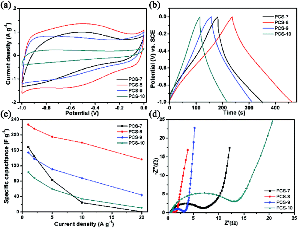 | ||
| Fig. 3 (a) CV curves of samples at a scanning rate of 10 mV s−1; (b) galvanostatic charge/discharge curves of samples at a specific capacitance of 1 A g−1; (c) specific capacitance of samples at different specific currents; (d) Nyquist plots of samples. | ||
To further evaluate the electrochemical performances, the galvanostatic charge–discharge measurements of all samples also were performed. Fig. 3(b) shows the galvanostatic charge–discharge curves of all samples between −0.1 V and 0 V at the specific current of 1 A g−1, which displays a slightly – distorted triangular shape, indicating Faraday redox electrochemical reactions of functional groups in electrodes. The specific capacitance, Cs (F g−1), was calculated by using the formula:
 | (1) |
The capacitive behavior of the porous carbon spheres electrodes was measured with impedance spectroscopy (Fig. 3(d)). By contrast, the PCS-8 has a smaller semicircle in the high frequency region, this means that it has a lower charge-transfer resistance between the electrolyte and the electrode. Combined with FT-IR analysis, 1380 cm−1 can be attributed to the symmetric stretching vibration of carboxylate ions (–COO–), and 1600 cm−1 (CO) can be attributed to the antisymmetric stretching vibration of carboxylate ions (–COO–). Carboxyl group is hydrophilic, so the carboxyl group can also improve the wettability of porous carbon surface, reduce the diffusion resistance of electrolyte ions in pores, and make the surface area of porous carbon electrode material fully utilized. Compared to CPS-8, these peaks of CPS-9 and CPS-10 are weaken, which indicate that the oxygen functional groups have been decomposed and transformed with the increase of pyrolysis temperature. So PCS-8 has a lower charge-transfer resistance between the electrolyte and the electrode. The PCS-9 has a larger slope of straight line than others at lower frequencies, which can be launched it has lower resistance of mass transfer. This phenomenon may be due to the PCS-9 has a larger volume of mesopore, this can be able to shorten ion transport distance and accelerate ion transport process.
In order to confirm the performance durability of the sample PCS-8, galvanostatic charge–discharge tests at the constant current density of 2 A g−1 up to 10000 cycles were carried out (Fig. 4). The specific capacitance of PCS-8 shows decrease at beginning and then increase with the charge/discharge cycles. The specific capacitance increases about 2% after 10000 cycles. This phenomenon5,32 is attributed to the only large pores and mesoporous are infiltrated by electrolyte at the beginning, while less micro pores has been wetted. The utilization ration of the micro pores is high with the prolongation of the charge and discharge time. And the K+ hydrated ions can be gradually penetrate into the pore and participate in the establishment of electric double layer. Results of the experiments show that the process is along with the charging and discharging. So the specific capacitance value increased by the gradual reduction of the mass transfer resistance and reaches a stable value at last.
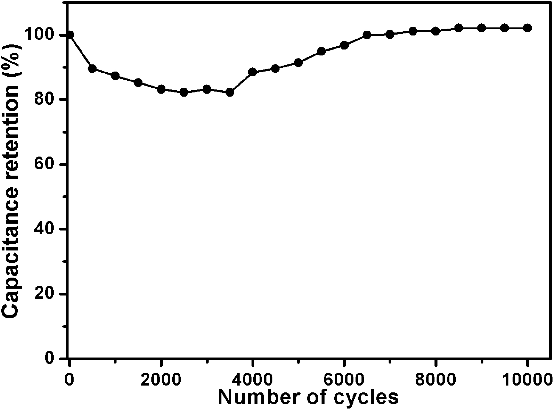 | ||
| Fig. 4 The cycle lifetime of PCS-8 at 2 A g−1. | ||
Furthermore, the coal based porous carbon spheres (PCS-8) was packaged as symmetric devices with two identical electrodes, and was tested electrochemical in two-electrode cell with 6 M KOH. The CV curves of the sample PCS-8 at scanning rates from 5 to 50 mV s−1 and its GCD curves in the potential range from 0 V to 1 V at current densities from 0.2 A g−1 to 5 A g−1 are shown in Fig. S5.† The CV curves of PCS-8 show quasi-rectangular shape at different scanning rates, indicating double layer capacitive behavior. Redox peaks could be observed at around 0.4 V, which illustrates the existence of Faraday actions. The GCD plots of the sample display a quasi-triangular shape, suggesting double layer capacitive mechanism for energy storage. The specific capacitance of a single electrode was calculated based on the following eqn (2):
 | (2) |
4. Conclusions
In summary, coal can be dissolved in alkaline solution after using a simple liquid-phase oxidation process, then we have proposed a green, facile and efficient strategy to prepare hierarchical porous carbon spheres using coal oxide as precursor by a simple one-pot spray pyrolysis. The specific surface area and pore structure of PCS can be easily modulated by the pyrolysis temperature. Moreover, PCS exhibited well electrochemical performances. In three-electrode cell configuration, the specific capacitance of PCS-8 shows a high specific capacitance 227 F g−1 at a current density of 1 A g−1 and outstanding cycling stability after 10000 charge/discharge cycles at a current density of 2 A g−1. In two-electrode cell, the specific capacitance of PCS-8 is 162 F g−1 at a current density of 1 A g−1 and has excellent rate capability. The results of our study demonstrate that a simple method to fabricate hierarchical porous carbon from coal resources has potential applications for a wide range of energy devices.
Conflicts of interest
There are no conflicts to declare.Acknowledgements
This work was supported by the National Natural Science Foundation of China (21571152 and U1203292), National 973 Program on Key Basic Research Project of China (2014CB660805), the Outstanding Youth Natural Science Foundation of Xinjiang Uygur Autonomous Region of China (201311006).Notes and references
- G. P. Wang, L. Zhang and J. J. Zhang, Chem. Soc. Rev., 2012, 41, 797–828 RSC.
- H. Zhang, G. P. Cao, Y. S. Yang and Z. N. Gu, Carbon, 2008, 46, 30–34 CrossRef CAS.
- R. Kötz and M. Carlen, Electrochim. Acta, 2000, 45, 2483–2498 CrossRef.
- M. Winter and R. J. Brodd, Chem. Rev., 2004, 104, 4245–4270 CrossRef CAS PubMed.
- P. Simon and Y. Gogotsi, Nat. Mater., 2008, 7, 845–854 CrossRef CAS PubMed.
- X. H. Lu, M. H. Yu, G. M. Wang, Y. X. Tong and Y. Li, Energy Environ. Sci., 2014, 7, 2160–2181 Search PubMed.
- Y. G. Wang, Y. F. Song and Y. Y. Xia, Chem. Soc. Rev., 2016, 45, 5925–5950 RSC.
- D. Y. Qu and H. Shi, J. Power Sources, 1998, 74, 99–107 CrossRef CAS.
- J. H. Chen, W. Z. Li, D. Z. Wang, S. X. Yang, J. G. Wen and Z. F. Ren, Carbon, 2002, 40, 1193–1197 CrossRef CAS.
- Y. P. Zhai, Y. Q. Dou, D. Y. Zhao, P. F. Fulvio, R. T. Mayes and S. Dai, Adv. Mater., 2011, 23, 4828–4850 CrossRef CAS PubMed.
- C. G. Liu, Z. N. Yu, D. Neff, A. Zhamu and B. Z. Jang, Nano Lett., 2010, 10, 4863–4868 CrossRef CAS PubMed.
- C. Tran and V. Kalra, J. Power Sources, 2013, 235, 289–296 CrossRef CAS.
- J. Z. Chen, J. L. Xu, S. Zhou, N. Zhao and C. P. Wong, Nano Energy, 2016, 25, 193–202 CrossRef.
- J. L. Yu, J. Lucas, V. Strezov and T. Wall, Fuel, 2003, 82, 2025–2032 CrossRef CAS.
- K. Moothi, S. E. Iyuke, M. Meyyappan and R. Falcon, Carbon, 2012, 50, 2679–2690 CrossRef CAS.
- L. S. K. Pang, A. M. Vassallo and M. A. Wilson, Nature, 1991, 352, 480 CrossRef.
- L. S. K. Pang and M. A. Wilson, Energy Fuels, 1993, 7, 436–437 CrossRef CAS.
- K. Hatakeyama, C. Ogata, M. Koinuma, T. Taniguchi, S. Hayami, K. Kuroiwa and Y. Matsumoto, ACS Appl. Mater. Interfaces, 2015, 7, 23041–23046 CAS.
- J. S. Qiu, F. Zhang, Y. Zhou, H. M. Han, D. S. Hu, S. C. Tsang and P. J. F. Harris, Fuel, 2002, 81, 1509–1514 CrossRef CAS.
- Q. Zhou, Z. B. Zhao, Y. T. Zhang, B. Meng, A. N. Zhou and J. S. Qiu, Energy Fuels, 2012, 26, 5186–5192 CrossRef CAS.
- X. J. He, N. Zhao, J. S. Qiu, N. Xiao, M. X. Yu, C. Yu, X. Y. Zhang and M. D. Zheng, J. Mater. Chem. A, 2013, 1, 9440–9448 CAS.
- X. J. He, H. B. Zhang, H. Zhang, X. J. Li, N. Xiao and J. S. Qiu, J. Mater. Chem. A, 2014, 2, 19633–19640 CAS.
- Y. T. Zhang, J. K. Li, G. Y. Liu, J. T. Cai, A. N. Zhou and J. S. Qiu, New Carbon Materials, 2017, 31, 545–549 Search PubMed.
- M. X. Guo, J. X. Guo, D. Z. Jia, H. Y. Zhao, Z. P. Sun, X. L. Song and Y. H. Li, J. Mater. Chem. A, 2015, 3, 21178–21184 CAS.
- X. L. Song, J. X. Guo, M. X. Guo, D. Z. Jia, Z. P. Sun and L. X. Wang, Electrochim. Acta, 2016, 206, 337–345 CrossRef CAS.
- Y. T. He, L. X. Wang and D. Z. Jia, Electrochim. Acta, 2016, 194, 239–245 CrossRef CAS.
- H. Y. Zhao, L. X. Wang, D. Z. Jia, W. Xia, J. Li and Z. P. Guo, J. Mater. Chem. A, 2014, 2, 9338–9344 CAS.
- A. C. Ferrari and J. Robertson, Phys. Rev. B: Condens. Matter Mater. Phys., 2001, 64, 075414 CrossRef.
- L. L. Zhang and X. S. Zhao, Chem. Soc. Rev., 2009, 38, 2520–2531 RSC.
- B. Liu, Y. Liu, H. Chen, M. Yang and H. Li, J. Power Sources, 2017, 341, 309–317 CrossRef CAS.
- C. Tang, Y. Liu, D. Yang, M. Yang and H. Li, Carbon, 2017, 122, 538–546 CrossRef CAS.
- J. S. Huang, B. G. Sumpter and V. Meunier, Angew. Chem., Int. Ed., 2008, 47, 520–524 CrossRef CAS PubMed.
Footnote |
| † Electronic supplementary information (ESI) available: FT-IR spectra, XRD patterns and Raman spectra of materials. See DOI: 10.1039/c7ra08026c |
| This journal is © The Royal Society of Chemistry 2017 |