
 Open Access Article
 This Open Access Article is licensed under a Creative Commons Attribution-Non Commercial 3.0 Unported Licence
Heterogeneous catalytic synthesis of quinoline compounds from aniline and C1–C4 alcohols over zeolite-based catalysts†
Chen Huanga,
An Lia and
Zi-Sheng Chao *ab
*ab
aCollege of Chemistry and Chemical Engineering, Hunan University, Changsha, 410082, China. E-mail: zschao@yahoo.com; Fax: +86-731-88713257; Tel: +86-731-88713257
bCollege of Materials Science and Engineering, Changsha University of Science and Technology, Changsha, 410110, China
First published on 16th October 2017
Abstract
The synthesis of quinolines from aniline and a C1–C4 alcohol was conducted under gas-phase reaction conditions over a series of zeolite-based catalysts. The texture and acid properties of catalysts were characterized by XRD, FT-IR, BET and NH3-TPD techniques. It was found that the total yield of quinolines was positively related to the relative content of Lewis acid sites of the catalyst. Among others, the ZnCl2/Ni-USY-acid catalyst possessed the best performance. Over this catalyst, the reactions of aniline and most of the alcohols provided a 42.3–79.7% total yield of quinolones under mild conditions, however, those of aniline and methanol, ethanol and iso-propanol predominantly led to N-alkylanilines. Furthermore, the reaction pathways for synthesizing quinolines via aniline reacting with polyhydric alcohols or monohydric alcohols was proposed in our work.
Introduction
Quinolines (quinoline and substituted quinolines) are a type of important heterocyclic compound, which can be widely used as pharmaceuticals, fungicides, herbicides, corrosion inhibitors and functional chemicals.1–8 Various traditional routes involving liquid phase reaction, such as, Skraup,9,10 Doebner-Miller,11,12 Friedländer,13,14 Combes,15,16 and Pfitzinger methods,17 have been developed and utilized in the synthesis of quinolines. However, these routes all suffered from a few drawbacks, e.g., anhydrous reaction condition, volatile organic solvent, expensive or toxic feed, corrosive and/or costly homogeneous catalyst, prolonged reaction time, tedious work-up procedure and difficult recycling of the catalyst.9–13,15,18,19 In contrast, gas phase reaction route for the synthesis of quinolines employs an appropriate heterogeneous catalyst,20–25 which can solve effectively the above issues associated with liquid phase reaction route, and thus, it is receiving more and more attentions.In the gas phase reaction route, up till now, small molecular aldehydes or carbonyl compounds containing active hydrogen on α-carbon, such as, acetaldehyde, propionaldehyde and butyraldehyde, were most frequently employed as the raw materials, due to their high activity in the reaction with aniline to synthesize quinolines. However, these raw materials are usually toxic, expensive, and particularly, prone to polymerization during reaction.22,24–26 Relative to carbonyl compounds, small molecular alcohols are hard to polymerize, much more eco-friendly and cheaper, since they can be alternatively manufactured from the fermentation of biomass materials besides the chemical synthesis from fossil-based raw materials. This enables small molecular alcohols to be potential substitutes of carbonyl compounds in the synthesis of quinolines. In fact, few papers dealt with the application of alcohol as feedstock to synthesizing quinolines via gas phase reaction route.20,21,23 For examples, Campanati et al.21 obtained a 41% yield of 2-methyl-8-ethylquinoline from the reaction of ethylene glycol and 2-ethylaniline at 330 °C over K10 montmorillonite catalyst, while Reddy et al.23 reported a 65% yield of quinoline via the reaction of glycerol and aniline at 425 °C over mixed metal oxides catalyst in the presence of air. However, such kind of attempts has been very limited, excepting the above-mentioned reports in the literature. Therefore, an exploration on the utilization of various types of alcohols as feedstock in reacting with aniline to generate quinolines is of significant importance.
The catalysts for the synthesis of quinolines via gas phase reaction route reported in the literature included mainly metal halide clusters, K10, amorphous silica–alumina and mixed metal oxides.20,22–25 These catalysts usually presented low to middle activities for the generation of quinolines but low catalytic stabilities, due to their poor acid performance and textural properties. Zeolites represent an important class of porous materials that have found numerous applications in catalysis, especially in the pyrolysis of petroleum to gasoline, because of their unique and tunable acid performance, large stability of framework and well-defined microporous structure. Y-Type zeolite was employed as catalyst in the synthesis of substituted quinolines, showing an appreciable catalytic activity.24 However, zeolite catalysts usually had to face an issue of transport limitation caused by the slow diffusion rates of reactant and bulky product in microporous.27,28 In this respect, the issue is more serious, since quinolines are relatively bulky, relative to gasoline molecules. To reduce the diffusion limitation, mesostructured ultra-stable Y zeolite (USY) was more frequently employed as catalyst in a series of reactions,29–31 due to their modified acid performance and large average pore size and therefore high stability and catalytic activity. Mesoporous USY zeolite could be prepared by acid or alkali treatment,29,31–34 steam dealumination,30,32,35,36 or in situ synthesis with mesoporous structure-directing agent.37 Among others, the acid-treated method of USY zeolite was considered as the most simple and efficient one, and thus, accepted by many researchers. However, to the best of our knowledge, no report on the employment of acid-treated USY zeolite as catalyst for the synthesis of substituted quinolines had been documented in the literature.
In this paper, we reported for the first time the systematical studies on the synthesis of quinolines from aniline and a C1–C4 alcohols over modified USY catalysts via gas phase route. It was clarified that the transition metal-modified mesoporous USY could be used as an efficient catalyst for the reaction of various alcohols and aniline to quinolines, exhibiting not only a high catalytic activity but also a good catalyst stability. Furthermore, the related reaction mechanisms, dependent on the type of alcohols, were also proposed in this paper.
Results and discussion
Fig. 1 shows the XRD patterns for various catalysts. One can see that all the catalysts exhibit the characteristic diffraction peaks for the USY zeolite, and the Ni-USY-acid and ZnCl2/Ni-USY-acid catalysts do not shown the diffraction peaks for Ni and ZnCl2 species. The intensities of diffraction peaks for the USY-acid, Ni-USY-acid and ZnCl2/Ni-USY-acid catalysts are all lower than for the parent USY. It shows that the original structure of USY zeolite is retained, though suffering from a destroy to some extent, after acid treatment, and Ni and ZnCl2 species possess very small dimension and have been highly dispersed on USY zeolite. From the enlargement of diffraction peaks, e.g., those ranging from 9.5° to 12.5°, one can find that the diffraction peaks shift slightly towards higher angel over the USY-acid catalyst but obviously towards lower angel over both the Ni-USY-acid and ZnCl2/Ni-USY-acid catalysts, relative to the parent USY zeolite. As is well known, the difference in the diameters of framework T atoms causes theoretically the expanse or contraction of zeolite framework and thus the whole shift of characteristic diffraction peaks of zeolite,38 while the diameters of the 4-coordinated ions Zn2+ (74 pm), Ni2+ (69 pm), Al3+ (53 pm) and Si4+ (40 pm) decrease sequentially. It is therefore deduced that the partial dealumination occurs during acid treatment of USY zeolite29 and a proportion of Ni and Zn ions are inserted into the framework during the Ni ion exchange and ZnCl2 loading over USY-acid zeolite.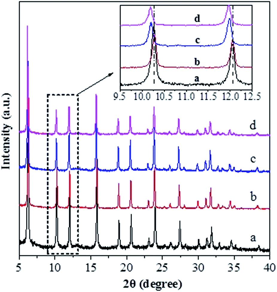 | ||
| Fig. 1 XRD patterns for the unmodified and modified USY zeolite catalysts: (a) USY; (b) USY-acid; (c) Ni-USY-acid; (d) ZnCl2/Ni-USY-acid (the inset is the enlargement of the patterns for 2θ = 9.5–12.5°). | ||
Fig. 2 shows FT-IR the spectra of various catalysts. The bands at ca. 1188, 1064 and 824 cm−1 over the USY catalyst are characteristic of TO4 tetrahedron units, which can be assigned to the external asymmetric, internal asymmetric and external symmetric stretching vibrations of Si–O–T linkages for TO4 (T = Si and/or Al) tetrahedral.39–41 These bands are known to shift towards higher wavenumbers with increasing the Si/Al molar ratio of zeolite. Besides, the band at 455 cm−1 over the USY catalyst is attributed to the internal T–O bending vibration of TO4 tetrahedron,42 and this band is nearly unaffected by the Si/Al molar ratio of zeolite. Compared to the USY catalyst, the Si–O–T stretching vibrations at 1188, 1064 and 824 cm−1 shift respectively to 1192, 1068 and 825 cm−1 over the USY-acid catalyst, indicating that the partial dealumination of USY zeolite occurs during the its acid treatment. However, the above Si–O–T stretching vibrations shift respectively to 1178, 1059 and 820 cm−1, over the Ni-USY-acid and ZnCl2/Ni-USY-acid catalysts. Szostak et al.43 reported that the incorporation of gallium replaced the framework aluminum of zeolite and in turn led to the significant shift of Si–O–T stretching vibrations towards lower wavenumber, due to the change in the reduced mass of the Si–O–T harmonic oscillator. Accordingly, the above variations in the Si–O–T stretching vibrations can be due to the incorporations of a proportion of Ni and/or Zn ions into the framework of USY-acid zeolite. The above results are consistent with those derived from XRD characterization.
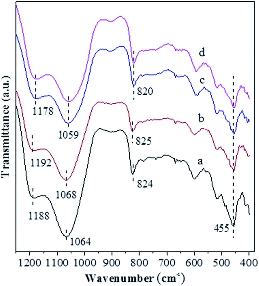 | ||
| Fig. 2 FT-IR spectra for the unmodified and modified USY zeolite catalysts: (a) USY; (b) USY-acid; (c) Ni-USY-acid; (d) ZnCl2/Ni-USY-acid. | ||
Fig. 3 shows the N2 adsorption–desorption isotherms for various catalysts, and the corresponding textural properties are summarized in Table 1. One can see from Fig. 3 that, for all the catalysts, the isotherms rise steeply at very low relative pressure, showing the presence of micropores. In addition, the hysteresis loop at P/P0 > 0.4 is obviously present for the USY-acid, Ni-USY-acid and ZnCl2/USY-acid catalysts but very unclear for the USY catalyst. It shows that mesopores are generated via the acid treatment of USY zeolite, of which the pore sizes range from 1.5 to 6.0 nm and possess a most possible value at ca. 2.0 nm (see the inset in Fig. 3). From Table 1, one can find that, compared to the USY catalyst, the USY-acid catalyst possesses a larger mesopore volume (Vmeso), total volume (Vtotal) and external surface area (Sext) but smaller micropore volume (Vmic), micropore surface area (Smic), micropore size (Dmic) and specific surface area (SBET). Besides, mesopores with an average size of 2.0 nm are determined for the USY-acid catalyst but not for the USY catalyst. It indicates that the generation of mesopores is a result of the partial dealumination of zeolite by acid treatment,44,45 and also, a proportion of extracted Al species may have occupied the micropores of zeolite. Compared to the USY-acid, the pore volumes (Vmeso, Vmic and Vtotal), surface areas (Sext, Smic and SBET) and pore size (Dmic and Dmes) all decrease sequentially over the Ni-USY-acid and ZnCl2/Ni-USY-acid. This can be due to the fact that, during the Ni ion exchange and ZnCl2 loading, a proportion of Ni2+ and Zn2+ ions enter into the pores and another proportion of Ni2+ and Zn2+ ions are incorporated into the framework of zeolite.
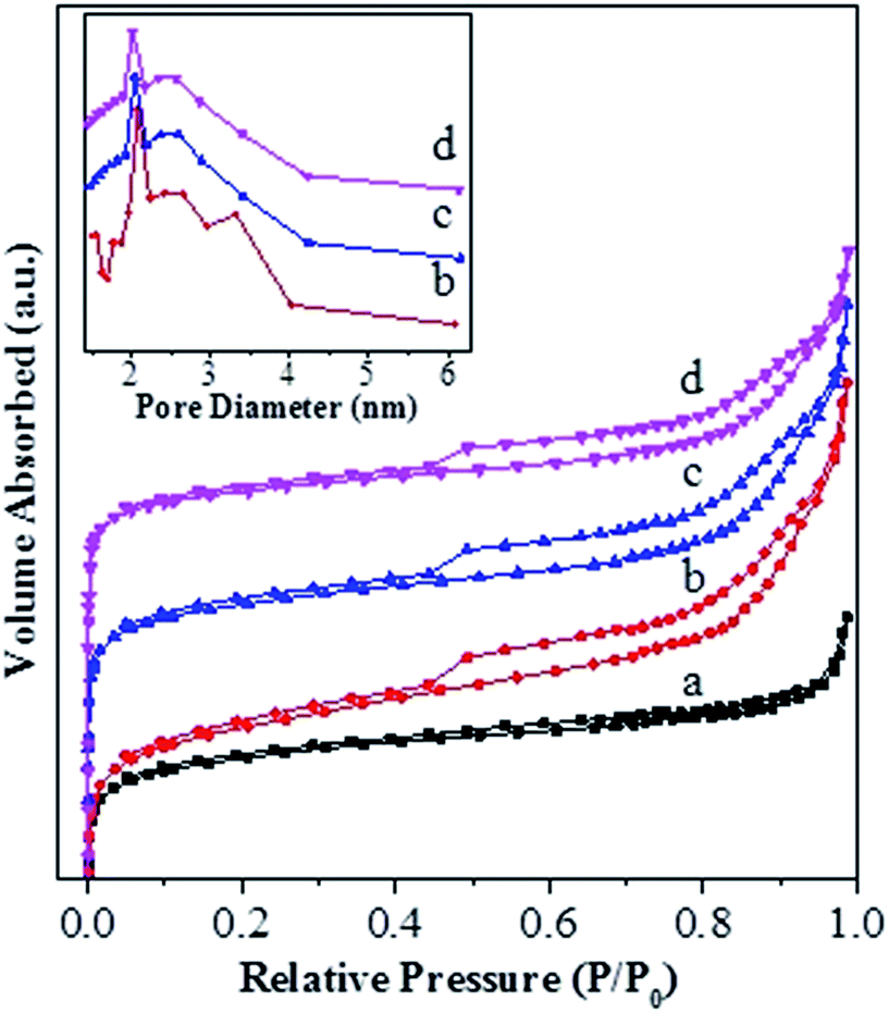 | ||
| Fig. 3 N2-adsorption/desorption isotherms and BJH pore-size distribution curves for the unmodified and modified USY zeolite catalysts: (a) USY; (b) USY-acid; (c) Ni-USY-acid; (d) ZnCl2/Ni-USY-acid. | ||
| Catalyst | SBETa (m2 g−1) | Smica (m2 g−1) | Sexta (m2 g−1) | Vmicb (cm3 g−1) | Vmesob (cm3 g−1) | Vtotalb (cm3 g−1) | Dmicroc (nm) | Dmesoc (nm) |
|---|---|---|---|---|---|---|---|---|
| a SBET, Sext and Smic: specific surface area, external surface area and micropore surface area, respectively, and SBET = Sext + Smic.b Vtotal, Vmic and Vmeso: total pore volume, micropore volume and mesopore volume, respectively.c Dmicro and Dmeso: micropore pore size and average mesopore pore size, respectively. | ||||||||
| USY | 704 | 618 | 86 | 0.21 | 0.09 | 0.30 | 0.74 | — |
| USY-acid | 664 | 536 | 128 | 0.19 | 0.19 | 0.38 | 0.73 | 2.08 |
| Ni-USY-acid | 631 | 512 | 119 | 0.18 | 0.18 | 0.36 | 0.73 | 2.04 |
| ZnCl2/Ni-USY-acid | 609 | 505 | 104 | 0.17 | 0.16 | 0.33 | 0.70 | 2.01 |
Fig. 4 shows the NH3-TPD profiles for various catalysts. The temperatures at the maximum (Ti) and integral area (Ai) of the peaks, which correspond respectively to the strength and concentration of acid sites, are summarized in Table 2. The T1, T3 and T4 peaks are present over all the catalysts, and they have a maximum at ca. 141–147 °C, 265–280 °C and 330 °C, respectively. The T1 peak is attributed to the weak adsorption of ammonia molecule over the surface terminal silanol (Si–OH) group,46 while the T4 peak can be assigned to the surface Brönsted acid site, i.e., bridged hydroxyl group (Si–OH–Al), in Y-type zeolite.47 It is known that the extra-framework Al species behave as Lewis acid site and possess a weaker strength than the bridged hydroxyl group in Y-type zeolite.47 Accordingly, the T3 peak can be attributed to the Lewis acid site associated with the extra-framework Al specie. Over various catalysts, the area of T4 peak exhibits an order USY > USY-acid > Ni-USY-acid ≈ ZnCl2/Ni-USY-acid and that of T3 displays an inverse order, while the area of T1 peak has an order USY ≈ USY-acid > Ni-USY-acid > ZnCl2/Ni-USY-acid. The result can be due to the fact that, firstly, the acid treatment and Ni ion exchange both result in the partial dealumination of zeolite, and this decreases the concentration of Si–OH–Al groups but increases that of extra-framework Al species over the USY-acid and Ni-USY-acid catalysts, relative to the USY catalyst; secondly, the Ni ion exchange leads to the replacement of hydrogen ion in the surface Si–OH–Al, and also, to some extent, that in the surface Si–OH group, and this decreases both the concentrations of the two kinds of hydroxyl groups over the Ni-USY-acid catalyst, relative to the USY-acid catalyst; thirdly, it was reported that ZnCl2 could react with the surface hydroxyl groups of Mont-K 10 clay to form the Lewis acid sites (–O–Zn–Cl) by the thermal activation.48 Accordingly, the surface hydroxyl groups (Si–OH and Si–OH–Al) over the Ni-USY-acid catalyst can react with ZnCl2, and this decreases the concentrations of surface hydroxyl groups, and also, would generates the new Lewis acid site (–O–Zn–Cl) over the ZnCl2/Ni-USY-acid catalyst, relative to the Ni-USY-acid catalyst. In fact, a new peak T2 with its maximum at ca. 185 °C has been identified over the ZnCl2/Ni-USY-acid catalyst but not over the other catalysts, and this peak can be assigned to the new Lewis acid site related to the –O–Zn–Cl groups. It is observed that the desorption temperature for the T2 peak is lower than that for the T3 peak, and also, the desorption temperature for the T3 peak is lower over the ZnCl2/Ni-USY-acid and Ni-USY-acid catalysts than over the USY-acid and USY catalysts. This can be due to the facts that the Ni ion exchanged over the zeolite can behave as a kind of Lewis acid site, and thus, it contributes to the T3 peak, besides the extra-framework Al species over the ZnCl2/Ni-USY-acid and Ni-USY-acid catalysts. Also, the electronegativity for the Zn2+, Ni2+ and Al3+ increases sequentially, and accordingly, the strength for the corresponding Lewis acid sites increases in order. Besides the above T1–T4 peaks, a new peak T5 with its maximum at ca. 508 °C is also present over the ZnCl2/Ni-USY-acid, Ni-USY-acid and USY-acid catalysts but almost absent over the USY catalyst. It was reported that the partial removal of the Al atoms in the second-neighbor positions increased significantly the strengths of Bronsted acid sites in the Y-typed zeolite.49 Liu et al.50 found that the strength of acid sites in the micropores or small cages was stronger than that in the mesopores or larger cavities over the dealuminated USY zeolite. Besides, Fritz et al.51 and Beyerlein et al.52 found that the strength of the bridged Brönsted acid sites (Si–OH–Al groups) were increased obviously due to the inductive effect of extra-framework aluminum species. Accordingly, the peak T5 can be attributed to the strong Bronsted acid sites, which are generated due to the removal of some adjacent framework Al species, and/or the inducement of the normal Bronsted acid sites, particularly those in the micropores, by the extra-framework Al species. Compared that over the USY-acid catalyst, the areas of peak T5 over the Ni-USY-acid and ZnCl2/Ni-USY-acid catalysts decrease, particularly for the latter one. This may be due to the partial blockage of the micropores in zeolite by a proportion of Ni and Zn species, which can be evidenced by the N2-physisorption determination. From Table 2, one can also see that the ratio for the total concentration of Lewis acid sites to the total Bronsted acid sites over various catalysts, i.e., (A2 + A3)/(A4 + A5), exhibits an order ZnCl2/Ni-USY-acid > Ni-USY-acid > USY-acid > USY.
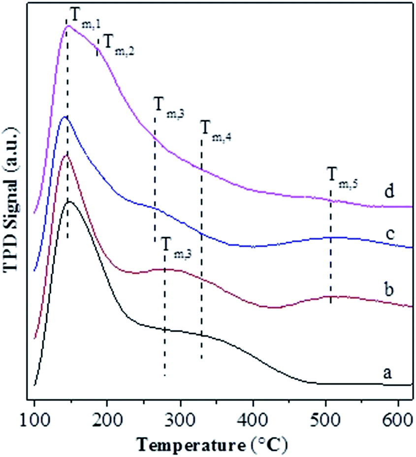 | ||
| Fig. 4 NH3-TPD profiles for the unmodified and modified USY zeolite catalysts: (a) USY; (b) USY-acid; (c) Ni-USY-acid; (d) ZnCl2/Ni-USY-acid. | ||
| Catalyst | Tia (°C) and Aib (mmol g−1) for various desorption peaks | (A2 + A3)/(A4 + A5) | |||||||||
|---|---|---|---|---|---|---|---|---|---|---|---|
| T1 | A1 | T2 | A2 | T3 | A3 | T4 | A4 | T5 | A5 | ||
| a Ti refers to the temperature (°C) at the maximum of desorption peak i.b Ai refers to the integral area of desorption peak i, and it also means the concentration (mmol g−1) of acid sites corresponding to the desorption peak i. | |||||||||||
| USY | 147 | 2.62 | — | — | 280 | 0.08 | 330 | 1.30 | — | — | 0.06 |
| USY-acid | 143 | 2.61 | — | — | 280 | 0.17 | 330 | 0.40 | 508 | 0.67 | 0.16 |
| Ni-USY-acid | 141 | 2.36 | — | — | 265 | 0.20 | 330 | 0.16 | 508 | 0.65 | 0.25 |
| ZnCl2/Ni-USY-acid | 144 | 1.54 | 185 | 1.77 | 265 | 0.21 | 330 | 0.05 | 508 | 0.05 | 19.80 |
Table 3 shows the results for the reaction of aniline and n-propanol over various catalysts. One can see that 2-ethyl-3-methyl-quinoline (2E-3MQ) over all the catalysts and 2,3-dimethylquinoline (DMQ), 2-ethylquinoline (2-EQ) and 3-methylquinoline (3-MQ) over some catalysts are generated. These products have an order 2E-3MQ ≫ DMQ ≫ 2-EQ ∼ 3-MQ. Besides, the byproducts, including predominantly N-propylaniline (NPA) and small amounts of 4-propylaniline, 2-propylaniline, N,N-dipropylaniline, and 3-methyl indole, are also identified in the product mixtures. Over the unmodified catalysts (entries 1, 3, 6, 9 and 11), the conversion of aniline exhibits an order USY-acid > USY > SiO2/Al2O3 > HZSM-5 > HY. This order is found to be approximately reverse to that for the concentrations of Brönsted acid sites over SiO2/Al2O3, HZSM-5 and HY is usually in the range of ca. 0.01–0.03 mmol g−1, 0.1–0.3 mmol g−1 and 1–3 mmol g−1, respectively; because of dealumination, the concentration of Brönsted acid sites over HY, USY and USY-acid decreases sequentially. Therefore, the lower concentration of Brönsted acid sites is favorable to the conversion of aniline, probably due to the smaller tendency for the deactivation of basic aniline by the protons of Brönsted acid sites. However, USY catalyst is also known to possess a higher concentration of Brönsted acid sites than SiO2/Al2O3 catalyst, while the former catalyst exhibits a larger conversion of aniline for the synthesis of quinolines than the later one. This is most probably because USY catalyst usually possesses a larger specific surface area (>700 m2 g−1) than SiO2/Al2O3 (<350 m2 g−1), enabling more active sites, e.g., Lewis acid sites, to be exposed for the activation and conversion of aniline. Both the total selectivity to quinolines (SQS) and total yield of quinolines (YQS) have an order USY-acid > USY > HY > HZSM-5 > SiO2–Al2O3. This can be due to the fact that the pores size of the zeolites employed in this work have an order USY-acid > USY > HY > HZSM-5, while quinolines possess a larger molecule size than the byproducts as mentioned above and therefore their formation is favorable in the larger pores than in the smaller pores. Moreover, zeolites are known to possess a narrow distribution of pore size and thus favor the selective formation of quinolines through cyclisation–aromatization, relative to the amorphous SiO2–Al2O3 that has a broad pore size distribution. One may have noticed that the selectivity to NPA as the predominant byproduct over the unmodified catalyst has an order USY-acid < USY < HY < HZSM-5 < SiO2–Al2O3, being just reverse to that for the total selectivity to quinolines. It hints that the generation of quinolines can be a result of the further conversion of NPA. Over the mono-metal-modified catalysts (entries 2, 4, 5, 7, 8, 10 and 12–16), particularly those modified by Ni, the conversion of aniline as well as the total selectivity to quinolines and total yield of quinolines are all increased, relative to the corresponding unmodified catalysts (entries 1, 3, 6, 9 and 11). Moreover, the total yield of quinolines over the modified catalysts exhibits the same order as that for the corresponding unmodified catalysts. It indicates that the modification of metal has presented a positive effect on the catalytic performance, and the promotion effect of metal display an order Ni > Fe > Co > Cu > Zn. The Ni-USY-acid catalyst (entry 16) provides a 38.5% total yield of quinolines with 68.6% conversion of aniline and 56.1% total selectivity to quinolines. Over the ZnCl2 further modified Ni-USY-acid catalyst, i.e., ZnCl2/Ni-USY-acid (entry 17), the total yield of quinolines is found to increase significantly, providing an as high as 97.6% conversion of aniline with 79.7% total selectivity to quinolines. Besides, compared to that (40.1%) over the Ni-USY-acid catalyst, the selectivity to NPA (9.3%) decreases obviously over the ZnCl2/Ni-USY-acid catalyst. As is well known, transition metal ions behave as Lewis acids, while ZnCl2 as a Lewis acid catalyst has exhibited good performances in many reactions like Friedel–Crafts alkylation.50,51,53 Therefore, the larger Lewis acidity is highly desired for the catalyst in the synthesis of quinolines from aniline and propanol, and ZnCl2 promotes not only the N-alkylation of aniline and n-propanol to generate NPA but also the further conversion of NPA to quinolines. After the carrier gas H2 is replaced with air, the total yield of quinolines is decreased obviously over the ZnCl2/Ni-USY-acid catalyst (cf. entries 17 and 18). It is known that the formation of quinolines from aniline and a carbonyl compound involves the cyclization-dehydrogenation step.22 Accordingly, the presence of low valent metal species, acting as both Lewis acid sites and dehydrogenating active centers, is vital for a catalyst to provide high performance in the synthesis of quinolines from aniline and alcohol. The above results indicate that the ZnCl2/Ni-USY-acid exhibits the highest catalytic performance among all the examined catalysts.
| Entry | Catalyst | Carrier gas | χb (mol%) | Sic (mol%) | SQSd (mol%) | YQSe (mol%) | ||||||
|---|---|---|---|---|---|---|---|---|---|---|---|---|
| 2E-3MQf | 2,3-DMQg | 2-EQh | 2-MQi | NPAj | DNPAk | Othersl | ||||||
| a Reaction condition: LHSV (aniline) = 0.4 h−1; molar ratio of propanol/aniline = 3; reaction temperature = 410 °C.b χ: conversion of aniline.c Si: selectivity to component i.d SQS: total selectivity to quinolines.e YQS: total yield of quinolines.f 2E-3MQ: 2-ethyl-3-methylquinoline.g 2,3-DMQ: 2,3-dimethylquinoline.h 2-EQ: 2-ethylquinoline.i 2-MQ: 2-methyl quinoline.j NPA: N-propylaniline.k DNPA: N,N-dipropylaniline.l Others: 2-propylaniline, 4-propylaniline and 3-methylindole. | ||||||||||||
| 1 | SiO2–Al2O3 | H2 | 51.3 | 7.6 | 0 | 0 | 0 | 85.3 | 0 | 7.1 | 7.6 | 3.9 |
| 2 | Ni/SiO2–Al2O3 | H2 | 55.4 | 8.4 | 0 | 0 | 0 | 86.2 | 0 | 5.4 | 8.4 | 4.7 |
| 3 | ZSM-5 | H2 | 42.5 | 9.7 | 0 | 0 | 0 | 71.4 | 0 | 18.9 | 9.7 | 4.1 |
| 4 | Fe-ZSM-5 | H2 | 45.1 | 11.2 | 1.3 | 0 | 0 | 74.5 | 0 | 13 | 12.5 | 5.6 |
| 5 | Ni-ZSM-5 | H2 | 44.4 | 11.3 | 1.8 | 0 | 0 | 72.3 | 0 | 14.6 | 13.1 | 5.8 |
| 6 | HY | H2 | 41.3 | 19.4 | 2.3 | 0 | 0 | 63.6 | 0 | 14.7 | 21.7 | 9.0 |
| 7 | Fe-Y | H2 | 48.6 | 24.2 | 2.2 | 0 | 1.3 | 62.7 | 0 | 9.6 | 27.7 | 13.5 |
| 8 | Ni-Y | H2 | 50.3 | 23.1 | 2.3 | 1.1 | 1.4 | 65.6 | 0 | 6.5 | 27.9 | 14.0 |
| 9 | USY | H2 | 55.3 | 29.1 | 8.3 | 1.1 | 3.4 | 43.6 | 0 | 14.5 | 41.9 | 23.2 |
| 10 | Ni-USY | H2 | 58.4 | 33.5 | 9.5 | 1.4 | 2.1 | 38.6 | 0 | 14.9 | 46.5 | 27.2 |
| 11 | USY-acid | H2 | 58.1 | 35.1 | 9.7 | 2.9 | 2.1 | 41.5 | 3.1 | 5.6 | 49.8 | 28.9 |
| 12 | Zn-USY-acid | H2 | 60.2 | 36.1 | 9.3 | 1.5 | 1.3 | 43.1 | 3.3 | 5.4 | 48.2 | 29.0 |
| 13 | Cu-USY-acid | H2 | 63.3 | 34.2 | 10.6 | 2.1 | 1.9 | 45.0 | 2.1 | 4.1 | 48.8 | 30.9 |
| 14 | Co-USY-acid | H2 | 61.4 | 36.7 | 11.4 | 2.3 | 2.0 | 41.4 | 2.5 | 3.7 | 52.4 | 32.2 |
| 15 | Fe-USY-acid | H2 | 62.3 | 42.8 | 11.3 | 1.4 | 1.5 | 38.6 | 2.6 | 1.8 | 57.0 | 35.5 |
| 16 | Ni-USY-acid | H2 | 68.6 | 42.5 | 11.6 | 1.3 | 0.7 | 40.1 | 1.9 | 1.9 | 56.1 | 38.5 |
| 17 | ZnCl2/Ni-USY-acid | H2 | 97.6 | 62.1 | 19.4 | 0.2 | 0 | 9.3 | 3.1 | 5.9 | 81.7 | 79.7 |
| 18 | ZnCl2/Ni-USY-acid | Air | 86.5 | 54.6 | 13.1 | 0.1 | 0 | 21.3 | 4.9 | 6.0 | 67.8 | 58.6 |
Fig. 5 illustrates the effects of various conditions on the conversion of aniline as well as the total selectivity to quinolines and the total yield of quinolines for the reaction of aniline and propanol over the ZnCl2/Ni-USY-acid catalyst, using H2 as carrier gas. Fig. 5(A) shows the effect of ZnCl2 loading in the catalyst. One can see that, with the increase of ZnCl2 loading, the conversion, selectivity as well as yield all increase obviously, achieving their maxima at 10 wt% ZnCl2 loading, and then decrease. While the loading of ZnCl2 introduces more Lewis active sites for the generation of quinolines, too large amounts of ZnCl2 may block the channels of zeolite catalyst so as to inhibit the diffusion of reactants and products. Fig. 5(B) shows the effect of temperature, which indicates that, with increasing the temperature, the conversion increases all through, however, both the selectivity and yield exhibit a maximum at 410 °C. This occurs owing to the fact that, though the increase in temperature promotes the activation and conversion of aniline and propanol over the catalyst, too higher temperatures may also lead to some side reactions, e.g., the cracking of reactants and products and the formation of carbon deposition. Fig. 5(C) shows the effect of the molar ratio of propanol/aniline, which indicates that, with increasing the molar ratio of propanol/aniline from 1 to 3, both the conversion and yield increase and the selectivity decreases. However, with further increasing the molar ratio of propanol/aniline, the conversion is almost unchanged, and both the selectivity and yield are decreased. This is due to the fact that, as mentioned from the discussion of Table 1, the generation of quinolines can be a result of the further conversion of NPA. Therefore, the increase in the molar ratio of propanol/aniline may lead to not only the conversion of NPA to N,N-dipropylaniline (DNPA) but also the direct reaction between aniline and propanol to other byproducts such as 2-propylaniline and 4-propylaniline, competing with the formation of quinolines. Fig. 5(D) shows the effect of LHSV (aniline). It can be seen that with increasing the LHSV, the conversion decreases all through and both the selectivity and yield exhibit a maximum, which appear at 0.6 h−1 and 0.4 h−1, respectively. This is because that the increase in LHSV decreases not only the contact time and thus the conversion of aniline over catalyst, but also the possibility of side reactions due to the fast diffusion of products away from the catalyst. However, a too higher LHSV would also lead to an insufficient adsorption and activation of aniline the thus its transformation into quinolines over the catalyst.
 | ||
| Fig. 5 Effect of reaction conditions on the synthesis of quinolines from aniline and propanol over the ZnCl2/Ni-USY-acid catalyst. (A) ZnCl2 loading; (B) reaction temperature; (C) molar ratio of propanol/aniline; (D) LHSV of aniline (the reaction is conducted under the conditions of temperature = 410 °C, molar ratio propanol/aniline = 3, LHSV = 0.4 h−1 and molar ratio of propanol/aniline = 3, one among which is varied for (A)–(D) while the others remaining unchanged). | ||
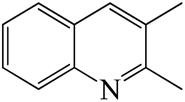
From Fig. 5, it is obtained that the optimized reaction conditions for the generation of quinolines from aniline and propanol over the ZnCl2/Ni-USY-acid catalyst are: ZnCl2 loading = 10 wt%; carrier gas = H2; temperature = 410 °C; molar ratio propanol/aniline = 3; and aniline LHSV = 0.4 h−1. Under those optimized reaction conditions, the conversion of aniline and total yield of quinolines are respectively 97.6 mol% and 79.7 mol% at 81.7 mol% total selectivity to quinolines. This provides a 60.6 mol% (54.3 wt%) GC yield of 2-ethyl-3-methylquinoline, according to Table 3.
Fig. 1S† shows the GC-MS chromatogram of the products mixture received from the reaction of aniline and propanol under the above optimized conditions. It is identified that 2-ethyl-3-methylquinoline has been generated as the main product. After separation and purification, the structure of the recovered 2-ethyl-3-methylquinoline is further confirmed by both 1H NMR(Fig. 2S†) and 13C NMR (Fig. 3S†) characterizations (1H NMR: δ = 8.03 (d, 1H, J = 8.4 Hz), 7.84 (s, 1H), 7.70 (d, 1H, J = 8.0 Hz), 7.61 (dd, 1H, J = 8.0, 7.2 Hz), 7.44 (dd, 1H, J = 7.6, 7.2 Hz), 3.02 (q, 2H, J = 7.6 Hz), 2.50 (s, 3H), 1.37 (t, 3H, J = 7.6 Hz); 13C NMR: δ = 163.30, 146.67, 135.73, 129.40, 128.52, 128.29, 127.33, 126.70, 125.61, 29.51, 19.10, 13.08). Besides, the purity of 2-ethyl-3-methylquinoline is determined as 98.6% from the 1H NMR characterization and the recovery yield of 2-ethyl-3-methylquinoline after separation and purification is determined as 90.2%, which corresponds to a 44.0 wt% separated yield (see ESI†).
Fig. 6 shows the conversion of aniline as well as the total selectivity to quinolines and the total yield of quinolines as functions of reaction time over the ZnCl2/Ni-USY-acid catalyst under the above optimized conditions. One can see that, within 30 h of reaction, the average level of the conversion of aniline, selectivity to quinolines and yield of quinolines remains at ca. 93%, 82% and 76%, respectively. For the reaction time longer than 30 h, the catalytic performance turns to decrease. This occurs probably due to either the formation of carbon deposition over the catalyst or the gradual loss of active ZnCl2 from the catalyst. In any way, the residual conversion of aniline, selectivity to quinolines and yield of quinolines still keep a level of 77%, 65% and 50%, respectively for the reaction time of 65 h. The above result shows that the ZnCl2/Ni-USY-acid possesses an appreciably good stability of catalytic performance.
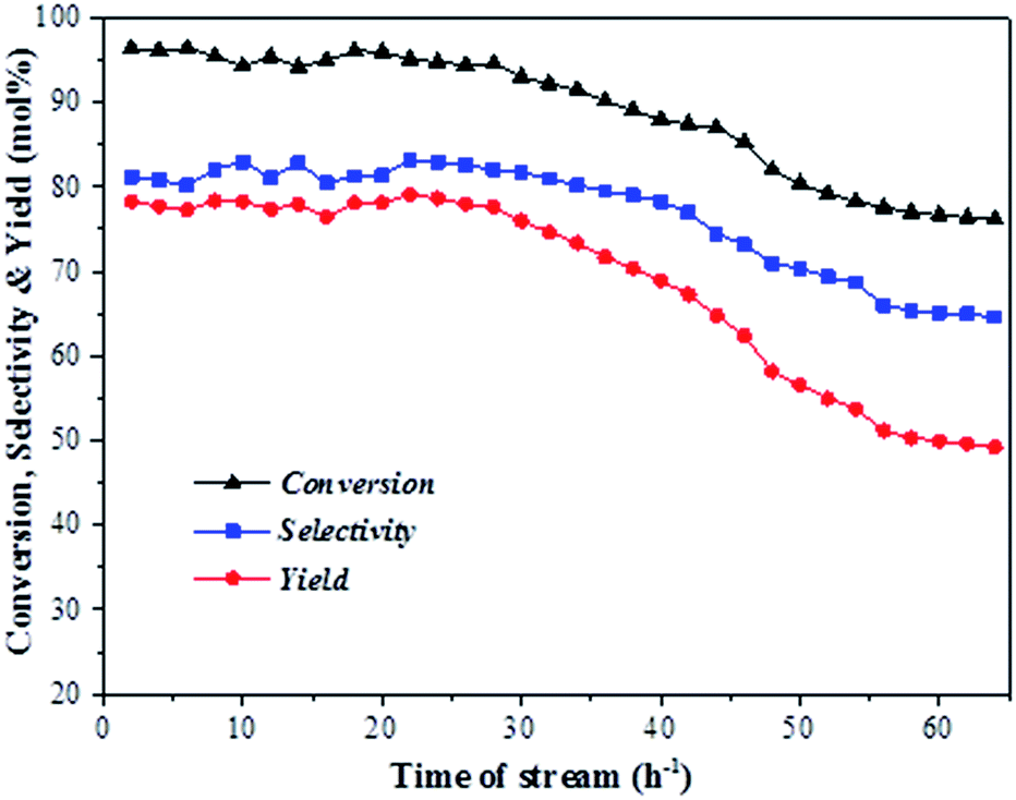 | ||
| Fig. 6 Lifespan of ZnCl2/Ni-USY-acid catalyst for the reaction of aniline and propanol to quinolones (reaction condition: carrier gas = H2; molar ratio of n-propanol/aniline = 3; LHSV (aniline) = 0.4 h−1; temperature = 410 °C). | ||
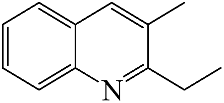
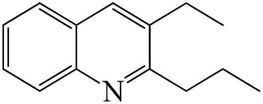
Table 4 shows the results for the reactions of aniline and C1–C4 alcohols (methanol, ethanol, n-propanol, iso-propanol, n-butanol, ethylene glycol, 1,2-propanediol and glycerol) over the ZnCl2/Ni-USY-acid catalyst. One can see that, for the reactions of aniline and C1–C2 monohydric alcohols, no quinolines but N-alkylaniline (NAA) is generated, and the yield of NAA is as high as 86.3–88.7%. For the reaction of aniline and polyhydric alcohols or C3–C4 monohydric alcohols, quinolines are generated as the main products, of which the total yield of quinolines is in the range of 42.3–79.7%, while N-alkylaniline is formed as the main byproduct. However, exception to the above regularity occurs for the reaction of aniline and iso-propanol, which leads to the generation of NAA (56.5% yield) as main product and quinolines (1.2% total yield) as minor ones. This probably because the steric effect of isopropyl group is disadvantageous to the dimerization of N-iso-propylaniline, which is the key step for the cyclization. It is identified that the most predominant quinolines generated by employing various alcohols are as follows: 2-ethyl-3-methyl-quinoline (n-propanol), 2-propyl-3-ethyl-quinoline (n-butanol), 2-methyl-quinoline (ethylene glycol), 2-ethyl-3-methyl-quinoline (1,2-propanediol) and quinoline (glycerol). This hints that, while quinoline is formed via the reaction between equimolecular aniline and glycerol, alkylquinolines are formed via the reaction between one molecular aniline and two molecular other proper C2–C4 alcohols. The above results also indicate the reaction of aniline and n-propanol, among all other alcohols, has provided the highest total yield of quinolines (79.7%).
| Reactant | Indoles yield (mol%) | NAAb yield (mol%) | Yield of quinolones (mol%) | ||||||
|---|---|---|---|---|---|---|---|---|---|
|
|
|
|
|
Othersc | Total yields | |||
| a Reaction condition: LHSV (aniline) = 0.4 h−1; molar ratio of propanol/aniline = 3; reaction temperature = 410 °C; carrier gas = H2.b NAA: N-alkylaniline, including NPA and DNPA.c Others: other substituted quinolines, such as, 2-ethylquinoline, 2-methyl-3-ethylquinoline. | |||||||||
| Methanol | 0 | 88.7 | 0 | 0 | 0 | 0 | 0 | 0 | 0 |
| Ethanol | 0 | 86.3 | 0 | 0 | 0 | 0 | 0 | 0 | 0 |
| n-Propanol | 1.2 | 12.1 | 0 | 0.2 | 18.9 | 60.6 | 0 | 0 | 79.7 |
| Iso-propanol | 1.1 | 56.5 | 0 | 1.2 | 0 | 0 | 0 | 0 | 1.2 |
| n-Butanol | 0 | 12.4 | 0 | 0 | 2.8 | 0 | 52.6 | 1.2 | 56.6 |
| Ethylene glycol | 9.7 | 6.6 | 0 | 56.1 | 3.7 | 9.4 | 0 | 2.6 | 71.8 |
| 1,2-Propanediol | 3.5 | 8.0 | 6.0 | 1.3 | 5.4 | 29.8 | 0 | 2.2 | 44.7 |
| Glycerol | 0.1 | 5.4 | 39.7 | 0.5 | 0 | 0 | 0 | 2.1 | 42.3 |
From the above results for the catalytic performance evaluation and catalyst characterization, it is obtained that both the total yield of quinolines from the reaction of aniline and n-propanol to quinolines and the relative content of Lewis acid sites exhibit an order ZnCl2/Ni-USY-acid > Ni-USY-acid > USY-acid > USY, but the porosity of catalyst displays a different order. Accordingly, the catalytic performance is positively related to the relative content of Lewis acid sites of catalyst.
Besides, for methanol, ethanol or iso-propanol as reactant, NAA is generated as the predominant product, almost without the generation of quinolines. For C2–C4 polyhydric alcohols or C3–C4 monohydric alcohols as reactant, the quinolines constructed theoretically by one molecular aniline and two molecular alcohols are generated as the predominant products, with NAA being generated as the most abundant byproduct. Exception to the above regularity is the case for glycerol as reactant, in which the predominant product quinoline is theoretically constructed by equimolecular aniline glycerol.
It has been reported that the mechanism for the synthesis of quinolines from aniline may involve either unsaturated aldehyde/ketone20,23,30 or Schiff base/Schiff base dimer54,55 as the key intermediate. As is well known, a C1–C4 monohydric alcohols very hard to be transformed into the corresponding aldehyde/ketone but easily dehydrated into the corresponding alkene over solid acid catalyst,56–58 and the reaction of amine and monohydric alcohol over molecular sieve catalyst has constituted the most important route for the synthesis of N-alkyl compound.58 Contrastively, it is feasible to convert a C2–C4 polyhydric alcohol into the corresponding aldehyde/ketone over solid acid catalyst, while aldehyde/ketone can be further converted into unsaturated aldehyde/ketone via Aldol reaction.59 Particularly, glycerol can be dehydrated directly into acrolein at high yield.23 In addition, the stable Schiff base is usually prepared from the reaction of aniline and aldehyde/ketone.58
Basing on the above facts, it is proposed that the reaction of aniline and alcohol to quinolines may follow the mechanisms as described by Scheme 1. For a C2–C4 polyhydric alcohol as reactant (Scheme 1A), it is first dehydrated into the corresponding aldehyde, which is further converted into unsaturated aldehyde via Aldol reaction. Then, the unsaturated aldehyde reacts with aniline via Michael addition, followed by cyclization and dehydrogenation-aromatization, and this finally generates quinolines. It is also possible that the aldehyde obtained from a C2–C4 polyhydric alcohol first reacts with aniline to generate the corresponding Schiff base. Then, the Schiff base is subjected to dimerization, cyclization and dehydrogenation–aromatization, and this finally generates quinolines. Specially, for glycerol as reactant, it is first directly dehydrated into acrolein, being an unsaturated aldehyde, and then subjected to the cyclization and dehydrogenation–aromatization, generating quinoline. For a C1–C4 alcohol as reactant (Scheme 1B), it first reacts with aniline to generate the corresponding N-alkylaniline, which is subsequently dehydrogenated into Schiff base. Then, the Schiff base is subjected to dimerize, cyclization and dehydrogenation–aromatization, and this finally generates quinolines. It should be addressed that the dimerization of Schiff base involves the generation of carbanion Ph = N–R−, which is impossible for R = methyl and very unstable for R = ethyl but relatively stable for larger alkyls. Therefore, only N-alkylanilines are generated from the reactions of aniline and methanol and ethanol, while quinolines can be predominantly formed from the reactions of aniline and n-propanol or n-butanol. Besides, there is a large steric effect for the dimerization of N-iso-propylaniline, and this accounts for the very low selectivity to quinolines but high selectivity to N-alkylaniline from the reaction between aniline and iso-propanol. In the above mechanism for the reaction of aniline and alcohol, the presence of Lewis acid sites promotes the adsorption activation of aniline and alcohols and the subsequent various steps, while the presence Bronsted acid sites may cause a few negative effects, e.g., the formation of inactive protonated aniline and the inhibition to the formation of carbanion Ph = N–R−. Therefore, the employment of the catalyst with high concentration ratio of Lewis acid sites to Bronsted acid sites is largely favorable to the synthesis of quinolines from aniline and alcohol, and this has been evidenced by the above results for catalyst characterization and catalytic performance evaluation.
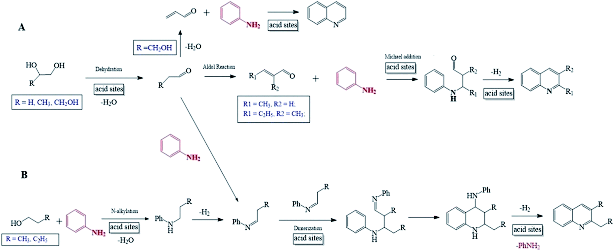 | ||
| Scheme 1 Reaction pathways for the synthesis of quinolines via the reactions of aniline and polyhydric alcohols (A) or monohydric alcohols (B). | ||
Experimental
Chemicals
All organic reagents for the synthesis of quinolines and inorganic salts for the preparation of catalysts were purchased from commercial companies and had purities higher than 99%. These chemicals were employed as received, without further purification.Zeolites USY (Si/Al = 10) and HY (Si/Al = 6) as well as amorphous SiO2–Al2O3 (Si/Al = 6–9) catalysts were all received from SINOPEC Catalyst Changling Division, and HZSM-5 (Si/Al = 50) were purchased from Shanghai Fuxu Zeolite Company. These catalysts were first calcined at 550 °C for 5 h, and then, they were either used directly as catalysts or further subjected to the procedures for the preparation of modified catalysts as described in the subsequent section.
Preparation of modified catalyst
Characterization of catalyst
X-ray diffraction spectroscopy (XRD) was performed with a Bruker D8-Advance X-ray diffractometer. The operation conditions were as follows: Cu target Kα ray (λ = 1.54187 Å); scanning voltage 40 kV, scanning current 40 mA; scanning speed 0.2 s, scanning step 0.02°.Fourier transform infrared (FT-IR) spectroscopy was recorded on a Varian 3100 spectrometer equipped with a GTGS detector. The catalyst was first mixed with KBr (1![[thin space (1/6-em)]](https://www.rsc.org/images/entities/char_2009.gif) :100) by thoroughly grounding, and then, the mixture was pressed into the sample holder and mounted in the cavity of the spectrometer. Each spectrum was obtained by scanning for 32 times at a resolution of 2 cm−1.
:100) by thoroughly grounding, and then, the mixture was pressed into the sample holder and mounted in the cavity of the spectrometer. Each spectrum was obtained by scanning for 32 times at a resolution of 2 cm−1.
N2-physisorption was performed at liquid nitrogen temperature using a QuantaChrome Autosorb-1 instrument. Before the adsorption measurement, the specimen degassed for 16 h at a temperature of 300 °C under a residual pressure lower than 4 × 10⁻⁴ Pa in the degas port of the adsorption apparatus. The specific surface area was calculated by using the multipoint BET equation. The pore volume and area was calculated by using the t-plot micropore analysis method. The pore size and its distribution of microporous were obtained from the N2-desorption branch employing the SF method, and those of mesoporous were determined from the N2-desorption branch by the BJH method.
Ammonia temperature programmed desorption (NH3-TPD) was determined on a Micromeritics AutoChem II 2920 instrument equipped with a thermal conductivity detector (TCD). The catalyst specimen was first degassed in a flow of helium with a flow rate of 50 mL min−1 at 400 °C for 30 min, followed by cooling to 100 °C. Then, NH3 was repeatedly pulse-injected until a saturation adsorption over the specimen had been achieved. After that, NH3 was desorbed by heating the specimen from 100 to 800 °C at a rate of 10 °C min. During the adsorption and desorption of NH3, the helium flow was retained and its flow rate was maintained constant at 60 mL min−1.
The metal contents of catalysts were determined over a Varian 240AA atomic absorption spectrometer. The operation conditions were as follows: sample aspiration rate = 3.0 mL min−1; lamp current = 3.0 mA; slit width = 0.2 nm; air flow rate = 0.8 mL min−1 and acetylene flow rate = 5.0 mL min−1.
Catalytic performance evaluation
Catalytic performance test was carried out in a fixed-bed tubular quartz reactor (i.d. 6 mm, total length 400 mm) at atmospheric pressure. The catalyst (1.0 g) was loaded in the middle of reactor, with the upper space of catalyst bed in the reactor being filled with quartz granulates (20 meshes). The mixture obtained by dissolving aniline into a C1–C4 alcohols (methanol, ethanol, n-propanol, iso-propanol, butanol, ethylene glycol, 1,2-propanediol and glycol) at a certain molar ratio (aniline/alcohol = 1/1–1/5) was employed as feedstock. Firstly, the catalyst was in situ pre-treated at certain reaction temperature ranging from 310 to 430 °C for 1 h in a flow of carrier gas (H2 or air; 10 mL min−1). Then, the feedstock was pumped into a preheater to be vaporized at 200 °C, at a liquid hourly space velocity (LHSV) ranging from 0.2–0.8 h−1. Then, the feedstock was introduced in to the reactor at a pre-set temperature, with the carrier gas being kept. After the reaction had been run stably for 2 h, the products were collected by a condenser which was placed in an ice-water bath.The composition of products mixture was analysed by a Varian CP-3800/Saturn 2200 gas chromatography-mass spectrometry (GC-MS). Two CP8944 capillary columns (VF-5, 30 m × 0.25 mm × 0.25 μm) were respectively connected to mass detector and flame ionization detector (FID) for the quantitative and qualitative identifications.
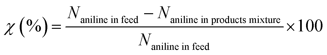
Basing on the converted aniline, the conversion of aniline (χ), selectivity to component i (Si) and yield of quinolines (YQS) were respectively calculated as follows:
Conversion of aniline (%):
Selectivity to component i (%):
Yield of component i (%):
| YQS (%) = χ × SQS × 100, |
Conclusions
The novel route for the synthesis of quinolines from the reaction of aniline and a C1–C4 alcohol under gas-phase reaction condition over heterogeneous catalyst had been developed in this work. It was identified that, for the reaction of aniline and propanol, the USY zeolite-based catalysts possessed obviously higher performances, relative to other catalysts. Over various modified USY catalysts, both the total yield of quinolines and the concentration ratio for Lewis acid sites to Bronsted acid sites exhibited an order USY < USY-acid < Ni-USY-acid < ZnCl2/Ni-USY-acid. Under the optimized conditions over the ZnCl2/Ni-USY-acid catalyst, the reaction of aniline and most of alcohols provided a 42.3–79.7% total yield of quinolines, however, the reaction of aniline and methanol, ethanol or iso-propanol predominantly generated N-alkylanilines. It was proposed that the mechanism for the formation of quinolines from aniline and alcohol involved mainly Schiff base as the key intermediate, while that involved unsaturated aldehyde also could not be excluded.Conflicts of interest
There are no conflicts of interest.Acknowledgements
We are grateful to the financial supports from the project #21376068 for National Natural Science Foundation of China (NSFC), Program for Lotus Scholar in Hunan Province, and also, Program for New Century Excellent Talents in University.References
- D. G. Markees, V. C. Dewey and G. W. Kidder, J. Med. Chem., 1970, 13, 324–326 CrossRef CAS PubMed.
- A. A. Alhaider, M. A. Abdelkader and E. J. Lien, J. Med. Chem., 1985, 28, 1394–1398 CrossRef CAS PubMed.
- Y. Morimoto, F. Matsuda and H. Shirahama, Synlett, 1991, 202–203 CrossRef.
- M. Isobe, T. Nishikawa, N. Yamamoto, T. Tsukiyama, A. Ino and T. Okita, J. Heterocycl. Chem., 1992, 29, 619–625 CrossRef CAS.
- V. V. Kouznetsov, L. Y. V. Méndez and C. M. M. Gómez, Curr. Org. Chem., 2005, 9, 141–161 CrossRef CAS.
- S. Eswaran, A. V. Adhikari, I. H. Chowdhury, N. K. Pal and K. D. Thomas, Eur. J. Med. Chem., 2010, 45, 3374–3383 CrossRef CAS PubMed.
- S. Gogoi, K. Shekarrao, A. Duarah, T. C. Bora, S. Gogoi and R. C. Boruah, Steroids, 2012, 77, 1438–1445 CrossRef CAS PubMed.
- V. V. Kouznetsov, C. M. Melendez Gomez, M. G. Derita, L. Svetaz, E. Del Olmo and S. A. Zacchino, Bioorg. Med. Chem., 2012, 20, 6506–6512 CrossRef CAS PubMed.
- Z. H. Skraup, Monatsh. Chem., 1880, 1, 316–318 CrossRef.
- R. H. F. Manske and M. Kulka, Org. React., 1953, 7, 59–93 Search PubMed.
- O. Doebner and W. V. Miller, Ber. Dtsch. Chem. Ges., 1881, 14, 2812–2817 CrossRef.
- W. P. Utermohlen, J. Org. Chem., 1943, 8, 544–549 CrossRef CAS.
- S. Concilio, P. M. Pfister, N. Tirelli, C. Kocher and U. W. Suter, Macromolecules, 2001, 34, 3607–3614 CrossRef CAS.
- G. Chelucci, I. Manca and G. A. Pinna, Tetrahedron Lett., 2005, 46, 767–770 CrossRef CAS.
- J. L. Born, J. Org. Chem., 1972, 37, 3952–3953 CrossRef CAS.
- S. A. Yamashkin, L. G. Yudin and A. N. Kost, Chem. Heterocycl. Compd., 1992, 28, 845–855 CrossRef.
- H. Zhu, R. F. Yang, L. H. Yun and J. Li, Chin. Chem. Lett., 2010, 21, 35–38 CrossRef CAS.
- K. Taguchi, S. Sakaguchi and Y. Ishii, Tetrahedron Lett., 2005, 46, 4539–4542 CrossRef CAS.
- Y. Tsuji, K. T. Huh and Y. Watanabe, J. Org. Chem., 1987, 52, 1673–1680 CrossRef CAS.
- M. Campanati, A. Vaccari and O. Piccolo, Catal. Today, 2000, 60, 289–295 CrossRef CAS.
- M. Campanati, P. Savini, A. Tagliani and A. Vaccari, Catal. Lett., 1997, 47, 247–250 CrossRef CAS.
- R. Brosius, D. Gammon, F. Vanlaar, E. Vansteen, B. Sels and P. Jacobs, J. Catal., 2006, 239, 362–368 CrossRef CAS.
- B. M. Reddy and I. Ganesh, J. Mol. Catal. A: Chem., 2000, 151, 289–293 CrossRef CAS.
- C. McAteer, R. D. Sr and J. Calvin, US Pat., 5700942, 1997.
- S. Kamiguchi, I. Takahashi, H. Kurokawa, H. Miura and T. Chihara, Appl. Catal., A, 2006, 309, 70–75 CrossRef CAS.
- J. R. Calvin, R. D. Davis and C. H. McAteer, Appl. Catal., A, 2005, 285, 1–23 CrossRef CAS.
- W. Schirmer, Phys. Chem., 1994, 186, 269–270 Search PubMed.
- D. M. Ruthven, Stud. Surf. Sci. Catal., 1995, 97, 223–234 CrossRef CAS.
- Z. Yan, D. Ma, J. Zhuang, X. Liu, X. Liu, X. Han, X. Bao, F. Chang, L. Xu and Z. Liu, J. Mol. Catal. A: Chem., 2003, 194, 153–167 CrossRef CAS.
- L. Zhang, W. Q. Fu, Q. P. Ke, S. Zhang, H. L. Jin, J. B. Hu, S. Wang and T. D. Tang, Appl. Catal., A, 2012, 433, 251–257 CrossRef.
- L. P. Zhou, H. T. Zhao, L. T. Cui, Y. Q. Bai, J. J. Bian, T. L. Lu, Y. L. Su and X. M. Yang, Catal. Commun., 2015, 71, 74–78 CrossRef CAS.
- A. H. Janssen, A. J. Koster and K. P. de Jong, J. Phys. Chem. B, 2002, 106, 11905–11909 CrossRef CAS.
- J. L. Agudelo, B. Mezari, E. J. M. Hensen, S. A. Giraldo and L. J. Hoyos, Appl. Catal., A, 2014, 488, 219–230 CrossRef CAS.
- D. Verboekend, G. Vilé and J. Pérez-Ramírez, Adv. Funct. Mater., 2012, 22, 916–928 CrossRef CAS.
- G. Tonetto, M. L. Ferreira and H. de Lasa, J. Mol. Catal. A: Chem., 2004, 216, 83–99 CrossRef CAS.
- D. D. Guo, B. J. Shen, Y. C. Qin, J. X. Sun, Q. X. Guo, S. Y. Ren, X. H. Gao, X. M. Pang, B. J. Wang, H. J. Zhao and H. H. Liu, Microporous Mesoporous Mater., 2015, 211, 192–199 CrossRef CAS.
- A. Ishihara, K. Inui, T. Hashimoto and H. Nasu, J. Catal., 2012, 29, 581–590 Search PubMed.
- C. W. Luo, C. Huang, A. Li, W. J. Yi, X. Y. Feng, Z. J. Xu and Z. S. Chao, Ind. Eng. Chem. Res., 2016, 55, 893–911 CrossRef CAS.
- I. Othman, R. M. Mohamed, I. A. Ibrahim and M. M. Mohamed, Appl. Catal., A, 2006, 299, 95–102 CrossRef CAS.
- L. Shirazi, E. Jamshidi and M. R. Ghasemi, Cryst. Res. Technol., 2008, 43, 1300–1306 CrossRef CAS.
- A. Vimont, F. Thibault-Starzyk and J. C. Lavalley, J. Phys. Chem. B, 2000, 104, 286–291 CrossRef CAS.
- C. S. Blackwell, J. Phys. Chem., 1979, 83, 3251–3257 CrossRef CAS.
- R. Szostak and T. L. Thomas, J. Catal., 1986, 101, 549–552 CrossRef CAS.
- A. Corma, Chem. Rev., 1997, 97, 2373–2420 CrossRef CAS PubMed.
- M. A. Kuehne, H. H. Kung and J. T. Miller, J. Catal., 1997, 171, 293–304 CrossRef CAS.
- N. Y. Topsøe, K. Pedersen and E. G. Derouane, J. Catal., 1981, 70, 41–52 CrossRef.
- B. Christian, P. Christoph, L. Michael, D. Frieder and B. Dieter, Microporous Mesoporous Mater., 2017, 241, 1–10 CrossRef.
- J. Massam and D. R. Brown, Catal. Lett., 1995, 35, 335–343 CrossRef CAS.
- J. R. Sohn, S. J. DeCanio, P. O. Fritz and J. H. Lunsford, J. Phys. Chem., 1986, 90, 4847–4851 CrossRef CAS.
- J. Liu, D. Yin, D. Yin, Z. Fu, Q. Li and G. Lu, J. Mol. Catal. A: Chem., 2004, 209, 171–177 CrossRef CAS.
- P. O. Fritz and J. H. Lunsford, J. Catal., 1989, 118, 85–98 CrossRef CAS.
- R. A. Beyerlein, G. B. McVicker, L. N. Yacullo and J. J. Ziemiak, J. Phys. Chem., 1988, 92, 1967–1970 CrossRef CAS.
- V. R. Choudhary, S. K. Jana and N. S. Patil, Catal. Lett., 2001, 76, 235–239 CrossRef CAS.
- C. S. Cho, J. S. Kim, B. H. Oh, T.-J. Kim, S. C. Shim and N. S. Yoon, Tetrahedron, 2000, 56, 7747–7750 CrossRef CAS.
- Y. Watanabe, Y. Tsuji, Y. Ohsugi and J. Shida, Bull. Chem. Soc. Jpn., 1983, 56, 2452–2457 CrossRef CAS.
- D. E. Bryant and W. L. Kranich, J. Catal., 1967, 8, 8–13 CrossRef CAS.
- R. Le Van Mao, P. Levesque, G. McLaughlin and L. H. Dao, Appl. Catal., 1987, 34, 163–179 CrossRef CAS.
- I. Takahara, M. Saito, M. Inaba and K. Murata, Catal. Lett., 2005, 105, 249–252 CrossRef CAS.
- S. Ito, K. Tanuma, K. Matsuda, A. Hayashi, H. Komai, Y. Kubota and M. Asami, Tetrahedron, 2014, 70, 8498–8504 CrossRef CAS.
Footnote |
| † Electronic supplementary information (ESI) available. See DOI: 10.1039/c7ra08442k |
| This journal is © The Royal Society of Chemistry 2017 |